Epson TM U295 - B/W Dot-matrix Printer Operator's Manual
Operation guide
Hide thumbs
Also See for TM U295 - B/W Dot-matrix Printer:
- User manual (45 pages) ,
- Manual (130 pages)
Table of Contents
Advertisement
Using this online operator's guide
The words on the left side of this screen are bookmarks for all the
topics in this guide.
Use the scroll bar next to the bookmarks to find any topic you
want. Click a bookmark to instantly jump to its topic. (If you wish,
you can increase the size of the bookmark area by dragging the
dividing bar to the right.)
Use the scroll bar on the right side of this screen to move through
the text.
Use the zoom tools to magnify or reduce the page display.
Click the Find button if you want to search for a particular term.
(However, using the bookmarks is usually quicker.)
Complete online documentation for Acrobat Reader is located in the Help directory for Acrobat Reader.
TM-U295/U295P
Operator's Manual
Return to main menu
Advertisement
Table of Contents

Related Manuals for Epson TM U295 - B/W Dot-matrix Printer


Summary of Contents for Epson TM U295 - B/W Dot-matrix Printer
- Page 1 TM-U295/U295P Operator’s Manual Using this online operator’s guide The words on the left side of this screen are bookmarks for all the topics in this guide. Use the scroll bar next to the bookmarks to find any topic you want. Click a bookmark to instantly jump to its topic. (If you wish, you can increase the size of the bookmark area by dragging the dividing bar to the right.) Use the scroll bar on the right side of this screen to move through...
- Page 2 TM-U295/U295P Operator’s Manual 400483605...
-
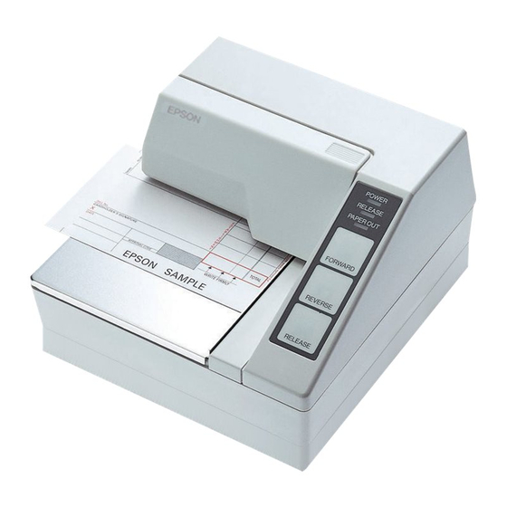
Page 3: Printer Parts
Printer parts (1) Upper case (2) Printer cover (3) Operation panel (4) Document table (5) POWER switch (6) Interface connector (7) FG (8) Drawer kick-out connector (9) Power connector (10) DIP switches (10) (10) (7) (8) (9) (7) (8) (9) TM-U295 TM-U295P... - Page 4 Seiko Epson Corporation. No patent liability is assumed with respect to the use of the information contained herein. While every precaution has been taken in the preparation of this book, Seiko Epson Corporation assumes no responsibility for errors or omissions.
-
Page 5: Fcc Compliance Statement
FCC CLASS A FCC Compliance Statement For American Users This equipment has been tested and found to comply with the limits for a Class A digital device, pursuant to Part 15 of the FCC Rules. These limits are designed to provide reasonable protection against harmful interference when the equipment is operated in a commercial environment. - Page 6 DECLARATION of CONFORMITY for CE MARKING Product Name: Printer Type Name: M66SA The printer conforms to the following Directives and Norms Directive 89/336/EEC EN 55022 (1986 and 1994) class B EN 50082-1 (1992) IEC 801-2 (1991) IEC 801-3 (1984) IEC 801-4 (1991) Directive 90/384/EEC EN45501: (1992)
- Page 7 DECLARATION of CONFORMITY for CE MARKING Product Name: Printer Type Name: M117A The printer conforms to the following Directives and Norms Directive 89/336/EEC EN 55022 (1986 and 1994) class B EN 50082-1 (1992) IEC 801-2 (1991) IEC 801-3 (1984) IEC 801-4 (1991) Directive 90/384/EEC EN45501: (1992)
-
Page 8: Introduction
After all the data for a page has been stored, it is printed. Bidirectional parallel interface in accordance with the IEEE 1284 Nibble/Byte Modes Please be sure to read the instructions in this manual carefully before using your new EPSON printer. -
Page 9: About This Manual
About This Manual Setting Up and Using Chapter 1 contains information on setting the printer up and setting the DIP switches. Chapter 2 contains information on using the printer. Chapter 3 contains troubleshooting information. Reference Chapter 4 contains specifications Notes, Cautions, and Warnings Note: Notes have important information and useful tips on the operation of your printer. -
Page 10: Table Of Contents
Contents Introduction ............v Chapter 1 Installation Unpacking . - Page 11 Chapter 5 Commands Command Notation ........... . 5-1 Control Commands .
-
Page 12: Chapter 1 Installation
Chapter 1 Installation Unpacking When you unpack the TM-U295 or TM-U295P printer, make sure you have these items. If any item is missing or damaged, please contact your dealer for assistance. Damper Ribbon cassette Hexagonal lock screws (2 pcs) (only for the TM-U295) Note: See the Note on page 1-3 for information about the screws. -
Page 13: Removing The Transportation Damper
Removing the Transportation Damper The printer is protected during shipping by a transportation damper that must be removed before you turn on the printer. 1. Pull the damper out and remove the strip of tape from the top of the printer, as shown below. Note: If you ever ship or store your printer, prepare it by performing these steps: turn on the printer, press the RELEASE button, press the... -
Page 14: Tm-U295
TM-U295 You need an appropriate serial interface cable to connect your computer to the printer. 1. Make sure that the printer and the computer are turned off. Then plug the cable into the connector on the back of the printer, as shown. Note: Your printer comes with inch-type hexagonal lock screws installed. -
Page 15: Tm-U295P
2. Connect the other end of the cable to the connector on your computer. TM-U295P You need an appropriate parallel interface cable to connect your computer to the printer. 1. Make sure that the printer and the computer are turned off. Then plug the cable into the connector on the back of the printer, as shown. -
Page 16: Connecting The Printer To The Drawer
Connecting the Printer to the Drawer Plug the drawer cable into the drawer kick-out connector on the back of the printer next to the computer interface connector. TM-U295 TM-U295P CAUTION: Do not connect a telephone line to the drawer kick out connector. - Page 17 Den Drucker an die Lade anschließen Das Kabel der Lade an die Schnappsteckerbuchse (neben der Schnittstellenbuchse) an der Hinterseite des Druckers anschließen. TM-U295 TM-U295P CAUTION: Kein Telefonkabel an die Schnappsteckerbuchse anschließen. 1-6 Installation...
-
Page 18: Grounding The Printer
Grounding the Printer You need an appropriate ground wire to ground your printer. Recommended wire is described below. Thickness of wire: AWG 18 or equivalent Diameter of terminal to be attached: 3.2 1. Make sure that the printer is turned off. 2. -
Page 19: Connecting The Power Supply
Connecting the Power Supply This printer requires an external power supply. The EPSON Power Supply PS-150 is recommended. CAUTION: Using an incorrect power supply can cause serious damage to the printer. 1. Make sure that the power supply is turned off. -
Page 20: Installing The Ribbon
3. Plug the power cord into an outlet. Installing the Ribbon Be sure to use a ribbon cassette that meets the printer’s specifications. The EPSON ERC-27 is recommended. Note: For instructions on replacing a used ribbon, see Chapter 2. 1. Turn the printer on using the power switch on its left side. - Page 21 CAUTION: Be sure to perform the steps above because it is necessary to make sure that the printer is in the paper release mode before you install the ribbon cassette. 4. Open the printer cover by slightly pressing the ridges on the top left and pulling the cover forward, as shown in the illustration below.
- Page 22 6. Carefully insert the ribbon cassette in the printer as shown in the illustration below. Notice exactly where the ribbon must go. 7. Then push firmly on the right side and then the left side of the ribbon cartridge until each side clicks into place. Installation 1-11...
-
Page 23: Inserting Paper
8. To put the cover back on the printer, first align the left and insert the tab on the top; then press the bottom until it clicks into place, as shown below. Inserting Paper Note: Do not use wrinkled or curled paper. For full information and specifications on the paper you can use, see Chapter 4. -
Page 24: Running The Self Test
4. Insert the paper from either the front or the side, as shown in the illustration below. Insert the paper into the printer until it is stopped by the form stopper. The markings on the side of the printer can also be used to judge how far to insert paper. 5. -
Page 25: Setting The Dip Switches
3. While holding down the RELEASE button, turn the printer back 4. Remove your finger from the RELEASE button. The printer prints the current printer settings and then eject the paper. 5. Press the RELEASE button to eject the paper completely and insert new paper to begin the second part of the test. - Page 26 2. Turn the printer over and locate the DIP switches, as shown below. 3. Notice that ON is marked on the set of switches. Use tweezers or another narrow tool to move the switches. 4. Use the following tables to set the DIP switches. Installation 1-15...
-
Page 27: Tm-U295
TM-U295 Switch Function Data reception error Ignored Prints”?” Receive buffer capacity 35 bytes 512 bytes Handshaking XON/XOFF DTR/DSR Word length 7 bits 8 bits Parity check Parity selection Even See Transmission Speeds table below. Pin 6 reset signal Used Not used Pin 25 reset signal Used Not used... -
Page 28: Tm-U295P
TM-U295P Switch Function Normally Normally Auto-line feed enabled disabled Receive buffer capacity 35 bytes 512 bytes Undefined Undefined Undefined Undefined Undefined Undefined Undefined Reserved. Setting must not be changed Note: If you change any DIP switch settings while the printer is turned on, the new settings will not take effect until you turn the printer off and back on or reset it. -
Page 29: Chapter 2 Using The Printer
Chapter 2 Using the Printer The control panel has three buttons and three lights. Buttons All three of these buttons can be disabled or enabled by the ESC c 5 command. RELEASE Pressing this button moves the rollers so that paper can be inserted or removed. -
Page 30: Replacing A Used Ribbon
RELEASE This light is on when the printer is in the paper release mode and it is off when the printer is in the clamp mode. Paper can be inserted only when the printer is in the paper release mode. This light blinks to indicate an error condition in the following cases: Paper jam... - Page 31 Then remove the used ribbon by grasping the handle and pulling straight out, as shown by the arrow in the illustration below. Then follow the rest of the steps in “Installing the Ribbon” in Chapter 1. Using the Printer 2-3...
-
Page 32: Chapter 3 Troubleshooting
Chapter 3 Troubleshooting This chapter gives the solutions to some printer problems. Power problems The POWER light does not come on. Make sure that the power supply cables are correctly plugged into the printer, the power unit, and to the power outlet. Make sure that power is supplied to the power outlet. -
Page 33: Printing Specifications
Chapter 4 Reference Information Printing Specifications Printing Method: Impact dot matrix Head Wires 7-pin shuttle type Printing Direction: Unidirectional 5 x 7 font: 1.9 to 2.3 Lines per second 7 x 7 font: 1.9 to 2.3 Characters per line 5 x 7 font: 35 7 x 7 font : 42 Characters per inch: 5 x 7 font: ANK: 0.63... - Page 34 Character structure: 5 x 7 with 1-dot spacing (normal dot) 7 x 7 with 3-dot spacing (half dot) Character size: 5 x 7 font: ANK: 1.6 mm (.063”) x 2.9 mm (.114”) Graphics: 1.9 mm (.075”) x 2.9 mm (.114”) 7 x 7 font: ANK: 1.3 mm (.051”) x 2.9 mm (.114”) Graphics: 1.6 mm (.063”) x 2.9 mm...
-
Page 35: Paper Specifications
Paper Specifications Paper type: Normal (high quality), pressure sensitive, and carbon copy papers Total thickness: Single-play paper: 0.09 to 0.25 mm (.0035 to .0098”) Copy paper: 0.09 to 0.35 mm (.0035 to .0138”) Paper size: 80 mm (W) 69 mm (L) to 182 mm 257 mm (L) (3.15”... - Page 36 Copy capability and Copying capability is influenced by ambient the ambient temperature. Printing temperature for must be performed under the conditions, described in a Table printing: below: Relationship between ambient temperature and number of copies Number of copies Ambient temperature (print mode) Original + 1 to 2 copies 5°...
-
Page 37: Printing Position
Printing position NOTE 1. Mechanical form stopper 12.5 (.49") NOTE 2. TOF sensor (fixed) Adjustable Printing position at minimum top margin 5 (.20") 65.84 (2.59") First printing position Paper feed roller Last printing position 12.5 (.49") NOTE 2. BOF sensor (fixed) Notes 1. -
Page 38: Electrical Specifications
Electrical Specifications Supply voltage: +24 VDC ± 10% Current consumption: Operating Mean - approx. (except for 600 mA at 24 drawer kick- VDC (full-column out): printing and data transmission of ANK characters) Peak - approx. 5.5 A at 24 VDC (full-column printing and data transmission of... -
Page 39: Emi And Safety Standards
EMI and Safety Standards EMI standards FCC: Class A (measured when CE marking: using the printer with the Epson PS-150): Safety standards: UL1950-2TH-D3 (Recognized component) CSA950-D3 (Recognized component) EN60950 (IEC950 2TH) Reliability Life: 3,000,000 lines End of Life is defined as the point at which the printer reaches the beginning of the Wearout Period. -
Page 40: Environmental Conditions
Serial interface: RS-232 compatible Parallel interface: IEEE 1284 compatible (Nibble/Byte Modes) Note: The interface is a factory installed option. One of the interfaces (serial or parallel) is already installed. Note: Refer to the EPSON TM-U295/U295P Specification for details. 4-8 Reference Information... -
Page 41: Command Notation
Chapter 5 Commands Command Notation [Name] The name of the command. [Format] The code sequence. ASCII indicates the ASCII equivalents. Hex indicates the hexadecimal equivalents. Decimal indicates the decimal equivalents. [ ]k indicates the contents of the [ ] should be repeated k times. [Range] Gives the allowable ranges for the arguments. -
Page 42: Control Commands
Control Commands [Name] Horizontal tab [Format] ASCII Decimal [Description] Moves the print position to the next horizontal tab position. [Notes] • Horizontal tab positions are set with ESC D. • Ignored unless the next horizontal tab position has been set. •... -
Page 43: Dle Eot N
[Description] Prints the data in the print buffer and returns to standard mode. [Notes] • The buffer data is deleted after being printed. • The printer does not execute paper ejection. • This command sets the print position to the beginning of the line. [Reference] ESC L [Name]... - Page 44 • This command should not be used within the data sequence of another command that consists of 2 or more bytes. For example, If you attempt to transmit ESC 3 n to the printer, but DTR (DSR for the host computer) goes to MARK before n is transmitted and then DLE EOT 3 interrupts before n is received, the code <10>H for DLE EOT 3 is processed as the code for ESC 3 <10>H.
- Page 45 Off/On Decimal Function Paper is not being fed by using the paper feed button. Paper is being fed by the paper feed button. Not used. Fixed to On. No paper-end stop. Printing stops due to paper end. No error. Error occurs. Not used.
- Page 46 n = 5: Slip paper status Off/On Decimal Function Not used. Fixed to Off. Not used. Fixed to Off. Slip paper selected. Does not wait for slip paper insertion. Waits for slip paper insertion. Not used. Fixed to On. Slip is detected by the BOF sensor. Slip is not detected by the BOF sensor.
- Page 47 [Description] Sets the character spacing for the right side of the character. [Notes] • The right-side character spacing for double-width mode is twice the normal value. • The character spacing is set in increment of half dot. • In page mode, the actual dot positions shift by half dot. •...
- Page 48 [Notes] • The printer can underline all characters (including the right-side character spacing), but cannot underline the space set by an HT. • When both double-height and double-width modes are selected, quadruple size characters are printed. • Only setting of underline mode specification have effect in page mode.
- Page 49 • d is the dot data for the characters. The dot pattern is in the horizontal direction from the left side. Any remaining dots on right side are blank. • The data to define a user-defined character is (y x) bytes. •...
- Page 50 •7 7 font when the dot pattern for code 32 (20H) is defined as shown below: p1 p2 p3 p4 p5 p6 p7 p8 p9 p10 ASCII code ESC & y c1 c2 x p1 p2 p3 p4 p5 p6 p7 Hex code 1B 25 01 20 20 07 1E 20 48 80 48 20 1E 5-10 Commands...
- Page 51 m nL n H [d]k [Name] Select bit-image mode [Format] ASCII nL nH [d]k nL nH [d]k Decimal nL nH [d]k [Range] m = 0, 1 k = nL + nH x 255 [Description] Selects a bit-image mode using m for the number of dots specified by nL and nH, as follows: Vertical direction Horizontal direction...
- Page 52 • The relationship between the image data and the dots to be printed is as follows: Print data Bottom Bit image data ESC 2 [Name] Select 1/6-inch line spacing [Format] ASCII Decimal [Description] Selects 1/6-inch line spacing. [Note] The line spacing can be set independently in standard mode and in page mode.
- Page 53 Decimal [Range] [Description] Selects device to which host computer sends data, using n as follows: Off/On Decimal Function Printer disabled. Printer enabled. Undefined. Undefined. Undefined. Undefined. Undefined. Undefined. Undefined. Undefined. Undefined. Undefined. Undefined. Undefined. Undefined. Undefined. [Notes] • When the printer is not selected, the printer ignores all received data until it is selected by this command.
- Page 54 [Notes] • The DIP switch settings are not checked again. • The data in the receive buffer is not cleared. • The macro definition is not cleared. ESC C n [Name] Set cut sheet eject length [Format] ASCII Decimal [Range] n 127 [Description] Sets the eject length for a cut sheet to n lines.
- Page 55 [Notes] • Up to 32 tab positions (k = 32) can be set. Data exceeding 32 tab positions is processed as normal data. • When [n]k is less than or equal to the preceding value [n]k-1, tab setting is finished and the following data is processed as normal data.
- Page 56 [Format] ASCII Decimal [Range] n 255 [Description] Prints the data in the print buffer and feeds the paper by n/60 inches in the reverse direction. [Notes] • This command is available only in standard mode. • The setting values do not remain. •...
- Page 57 Double-density bit image: ESC Paper release: ESC q • The following commands are settable but do not have any effect in page mode. Upside-down character mode: ESC { 7 font and underline mode specification and cancel: ESC ! • This command is effective only in standard mode. •...
- Page 58 ESC T n [Name] Select print direction in page mode [Format] ASCII Decimal [Range] [Description] Selects the print direction and starting position in page mode. n specifies the print direction and starting position as follows: Print Direction Starting Position Upper left 0, 48 Left to right (A in the figure)
- Page 59 dx = [dxL + dxH 256] dy = [dyL + dyH 256] The printable area is set as shown in the figure below. (0, 0) Printable area of the paper (x0, y0) Printing area (x0+dx-1, y0+dy-1) (209 dots, 479 dots) [Notes] •...
- Page 60 Decimal [Range] n 255 [Description] Selects paper sensor(s) to output paper end signals, using n as follows: Off/On Decimal Function Undefined. Undefined. Undefined. Undefined. Undefined. Undefined. Undefined. Undefined TOF sensor disabled. TOF sensor enabled. BOF sensor disabled. BOF sensor enabled. Undefined.
- Page 61 [Range] n 255 [Description] Selects the paper sensor(s) used to stop printing when a paper-end is detected, using n as follows: Off/On Decimal Function Undefined. Undefined. Undefined. Undefined. Undefined. Undefined. Undefined. Undefined. TOF sensor disabled. TOF sensor enabled. BOF sensor disabled. BOF sensor enabled.
- Page 62 Decimal [Range] n 255 [Description] Enables or disables the panel buttons. • When the LSB of n is 0, the panel buttons are enabled. • When the LSB of n is 1, the panel buttons are disabled. [Notes] • When the panel buttons are disabled, none of them are usable when the printer cover is closed.
- Page 63 [Description] Sets the time that the printer waits for slip paper to be inserted and the time from insertion of the sheet to the start of printing. • t1 specifies the wait time for a cut sheet to be inserted. There is no limitation for the wait time and the printer waits until slip paper is inserted.
- Page 64 [Reference] ESC c 4, ESC c5 ESC t n [Name] Select character code table [Format] ASCII Decimal [Range] [Description] Selects a page n from the character code table. Page (PC437 [U.S.A., Standard Europe]) (Katakana) (PC850 [Multilingual]) [Note] If n is outside the specified range, the printer ignores this command. [Default] n = 0 ESC u n...
- Page 65 • When Auto Status Back (ASB) is enabled using GS a, the status transmitted by ESC u and the ASB status must be differentiated. • If n is out of the specified range, the printer ignores this command. • The status to be transmitted is shown in the table below. Off/On Decimal Function...
- Page 66 • The 1 byte status data is transmitted after printing and paper feed operation completely stop (transmit timing differs from ESC u, GS I). • This command is executed when the data is processed in the receive buffer. Therefore, there may be a time lag between receiving the command and transmitting the status, depending on the receive buffer status.
- Page 67 [Description] Turns upside-down printing mode on or off. • When the LSB of n is 0, upside-down printing mode is turned off. • When the LSB of n is 1, upside-down printing mode is turned on. [Notes] • In upside-down printing mode, the printer rotates the line to be printed by 180°...
- Page 68 Off/On Decimal Function Undefined. Undefined. Not used. Fixed to Off. Undefined. Undefined. Undefined. Undefined. Not used. Fixed to Off. [Notes] • When DTR/DSR control is selected, the printer transmits only 1 byte after confirming that the host is ready to receive data (DSR signal is SPACE).
- Page 69 Off/On Decimal Status for ASB On-line/Off-line status disabled. On-line/Off-line status enabled. Error status disabled. Error status enabled. Undefined. Undefined. Undefined. Undefined. Slip sensor status disabled. Slip sensor status enabled. Undefined. Undefined. Undefined. Undefined. • If n = 0, ASB is disabled. [Notes] •...
- Page 70 First byte (printer information) Off/On Decimal Status for ASB Not used. Fixed to Off. Not used. Fixed to Off. Drawer kick-out connector pin 3 is LOW Drawer kick-out connector pin 3 is HIGH. On-line. Off-line. Not used. Fixed to On. Not used.
- Page 71 Third byte (paper sensor information) Off/On Decimal Status for ASB Undefined. Undefined. Undefined. Undefined. Undefined. Undefined. Undefined. Undefined. Not used. Fixed to Off. Slip is detected by BOF sensor. Slip is not detected by BOF sensor. Slip is detected by TOF sensor. Slip is not detected by TOF sensor.
- Page 72 Off/On Decimal Status for ASB Undefined. Undefined. Not used. Fixed to Off. Bit 1: • Becomes On (slip printing possible) when slip paper is detected and becomes Off (slip printing is not possible) when slip ejection starts or time-out. • When the printer goes to the slip wait status, bit 5 and 6 of the third byte are On (no paper) and bit 1 of the forth byte is On (slip printing is not possible).
- Page 73 • When Auto Status Back (ASB) is enabled using GS a, the status transmitted by GS r and the ASB status must be differentiated. • If the value of n is out of the specified range, the printer ignores this command. •...
- Page 74 Bit Off/On Decimal Status for ASB Not used. Fixed to Off. Undefined. Undefined. Undefined. Undefined. Not used. Fixed to Off. [Reference] DLE EOT, ESC u, ESC v, GS a 5-34 Commands...