Table of Contents
Advertisement
Advertisement
Table of Contents

Related Manuals for MSI 790FX GD70 - Motherboard - ATX


Summary of Contents for MSI 790FX GD70 - Motherboard - ATX
- Page 1 790FX-GD70 Series MS-7577 (v1.X) Mainboard G52-75771X1...
-
Page 2: Trademarks
Alternatively, please try the following help resources for further guidance. Visit the MSI website for FAQ, technical guide, BIOS updates, driver updates, an d ot h er i n f orm at i on: h t t p: / / g l o ba l . -
Page 3: Safety Instructions
Safety Instructions Always read the safety instructions carefully. Keep this User’s Manual for future reference. Keep this equipment away from humidity. Lay this equipment on a reliable flat surface before setting it up. The openings on the enclosure are for air convection hence protects the equip- ment from overheating. -
Page 4: Fcc-B Radio Frequency Interference Statement
FCC-B Radio Frequency Interference Statement T h is eq uip men t h as been tested and found to c omply with the limits for a Class B digital device, pursuant to Part 15 of the FCC Rules. These limits are designed to provide reasonable protection against harmful interference in a residential installation. -
Page 5: Weee (Waste Electrical And Electronic Equipment) Statement
WEEE (Waste Electrical and Electronic Equipment) Statement... -
Page 8: Table Of Contents
CONTENTS Copyright Notice ......................ii Trademarks ........................ii Revision History ......................ii Technical Support ......................ii Safety Instructions ......................iii FCC-B Radio Frequency Interference Statement ............iv W EEE (Waste Electrical and Electronic Equipment) Statement ........v Chapter 1. Getting Started ..................1-1 Mainboard Specifications ................... - Page 9 Appendix A Realtek Audio ................... A-1 Installing the Realtek HD Audio Driver ..............A-2 Software Configuration ..................A-4 Hardware Setup ....................A-19 Appendix B Overclocking Center ............... B-1 Activating Overclocking Center ................. B-2 System Info ......................B-3 DOT ........................B-5 Appendix C SB750 SATA RAID ................
-
Page 10: Chapter 1. Getting Started
Getting Started Chapter 1 Getting Started Thank you for choosing the 790FX-GD70 Series (MS- 7577 v1.X) ATX motherboard. The 790FX-GD70 Series ® motherboards are based on AMD 790FX & SB750 chipset for optimal system efficiency. Designed to fit ® the advanced AMD Phenom II X4/ X3 and Athlon X4/ X3/ X2 AM 3 processor, the 790FX-GD70 Series deliver a high performance and professional desktop... -
Page 11: Motherboard Specifications
M emory Support - DDR3 1066/ 1333/ 1600*/ 1800*/ 2133* SDRAM (total 16 GB Max) - 4 DDR3 DIMMs (240pin / 1.5V) (*means overclock, for more information on compatible components, please visit http://global.msi.com.tw/index.php? func=testreport) ® - Supports Dual Gigabit LAN by Realtek... - Page 12 Getting Started Hardware RAID ® - SATA7 & SATA8 support RAID 0/ 1 & JBOD mode by JMicron JMB322 Floppy - 1 floppy port - Supports 1 FDD with 360 KB, 720 KB, 1.2 MB, 1.44 MB and 2.88 MB Connectors Back panel - 1 PS/2 mouse/ 1 PS/2 keyboard port...
-
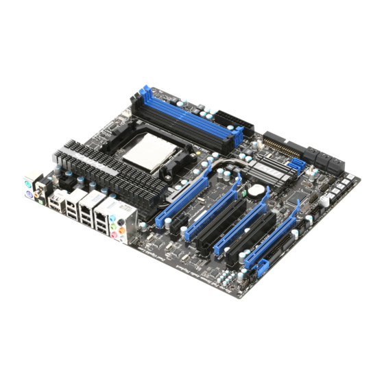
Page 13: Motherboard Layout
M S-7577 M ainboard Motherboard Layout CPUFA N1 Top : mouse Bottom: SY SFAN3 keyboard Top: Coaxial S/PDI F Buttom: Optical S/PDI F JP WM2 Top: USB Buttom: ES ATA/USB Common port Top:1394 (optional) Bottom: USB ports Top: LAN Jack Bottom: USB ports Top: LAN Jack Bottom: USB ports... -
Page 14: Packing Checklist
Getting Started Packing Checklist Back IO Shield MSI Driver/Utility CD MSI motherboard Power Cable SATA Cable IDE/ Floppy Cable CrossFire USB Bracket User’s Guide Video Link Cable * The pictures are for reference only and may vary from the packing contents of the... -
Page 15: Chapter 2. Hardware Setup
Hardware Setup Chapter 2 Hardware Setup This chapter provides you with the information about hardware setup procedures. While doing the installation, be careful in holding the components and follow the installation procedures. For some components, if you install in the wrong orientation, the components will not work properly. -
Page 16: Quick Components Guide
M S-7577 M ainboard Quick Components Guide JBAT1, p.2-19 SYSFAN4, p.2-13 CPU, p.2-3 SYSFAN3, p.2-13 JCI1, p.2-13 JPWM2, p.2-8 CPUFAN1, p.2-13 DDR3, p.2-6 Back Panel, p.2-9 JPWR1, p.2-8 SYSFAN2, p.2-13 SYSFAN1, p.2-13 PCIE Slots, p.2-22 IDE1, p.2-11 JSP1, p.2-16 SATA, p.2-12 PCI Slots, POST_LED, p.2-21 p.2-25... -
Page 17: Cpu (Central Processing Unit)
W hen you are installing the CPU, make sure to install the cooler to prevent overheating. If you do not have the CPU cooler, consult your dealer before turning on the computer. For the latest information about CPU, please visit http://global.msi.com.tw/index.php? func=cpuform2 Important Overheating Overheating will seriously damage the CPU and system. -
Page 18: Cpu & Cooler Installation
M S-7577 M ainboard CPU & Cooler Installation W hen you are installing the CPU, make sure the CPU has a cooler attached on the top to prevent overheating. Meanwhile, do not forget to apply some thermal paste on CPU before installing the heat sink/cooler fan for better heat dispersion. Follow the steps below to install the CPU &... - Page 19 Hardware Setup 5. Position the cooling set onto the re- 6. Then press down the other end of tention mechanism. the clip to fasten the cooling set on the top of the retention mechanism. Hook one end of the clip to hook first. Locate the Fix Lever and lift up it .
-
Page 20: Memory
M S-7577 M ainboard Memory These DIMM slots are used for installing memory modules. For more information on compatible components, please visit http://global.msi.com. tw/index.php?func=testreport DDR3 240-pin, 1.5V 72x2=144 pin 48x2=96 pin Dual-Channel Memory Population Rules In Dual-Channel mode, the memory modules can transmit and receive data with two data bus lines simultaneously. -
Page 21: Installing Memory Modules
Hardware Setup Installing Memory Modules 1. The memory module has only one notch on the center and will only fit in the right orientation. 2. Insert the memory module vertically into the DIMM slot. Then push it in until the golden finger on the memory module is deeply inserted in the DIMM slot. -
Page 22: Power Supply
M S-7577 M ainboard Power Supply ATX 24-pin Power Connector: JPWR1 pin 13 This connector allows you to connect an ATX 24-pin power supply. To connect the ATX 24-pin power supply, make sure the plug of the power supply is inserted in the proper orientation and the pins are aligned. -
Page 23: Back Panel
Hardware Setup Back Panel (optional) Coaxial M o us e 1394 Port S/PDIF-Out RS-Out Line-In USB Port Keyboard Line-Out CS-Out Optical SS-Out USB Port USB Port USB Port ESATA/USB S/PDIF-Out Co mm on Port M ouse/ Keyboard ® ® The standard PS/2 keyboard / mouse DIN connector is for a PS/2 keyboard / mouse. - Page 24 M S-7577 M ainboard The standard RJ-45 LAN jack is for connection to Yellow Green / Orange the Local Area Network (LAN). You can connect a network cable to it. Color LED State Condition LAN link is not established. Left Yellow On (steady state) LAN link is established.
-
Page 25: Connectors
Hardware Setup Connectors Floppy Disk Drive Connector: FDD1 This connector supports 360KB, 720KB, 1.2MB, 1.44MB or 2.88MB floppy disk drive. IDE Connector: IDE1 This connector supports IDE hard disk drives, optical disk drives and other IDE devices. Important If you install two IDE devices on the same cable, you must configure the drives separately to master / slave mode by setting jumpers. - Page 26 M S-7577 M ainboard Serial ATA Connector: SATA1~ SATA8 This connector is a high-speed Serial ATA interface port. Each connector can connect to one Serial ATA device. SATA1~6 stack SATA connectors are controlled by SB750 SATA1_2 SATA3_4 SATA5_6 SATA8 SATA7 SATA7 &...
- Page 27 Hardware Setup Fan Power Connectors: CPUFAN1, SYSFAN1/ 2/ 3/ 4 The fan power connectors support system cooling fan with +12V. W hen connecting the wire to the connectors, always note that the red wire is the positive and should be connected to the +12V; the black wire is Ground and should be connected to GND. If the motherboard has a System Hardware Monitor chipset on-board, you must use a specially designed fan with speed sensor to take advantage of the CPU fan control.
- Page 28 M S-7577 M ainboard TPM Module Connector: JTPM1 This connector connects to a TPM (Trusted Platform Module) module (optional). Please refer to the TPM security platform manual for more details and usages. Signal Description Signal Description LCLK LPC clock 3V_STB 3V standby power LRST# LPC reset...
- Page 29 Hardware Setup Front Panel Audio Connector: JAUD1 This connector allows you to connect the front panel audio and is compliant with ® Intel Front Panel I/O Connectivity Design Guide. HD Audio Pin Definition SIGNAL DESCRIPTION MIC_L Microphone - Left channel Ground MIC_R Microphone - Right channel...
- Page 30 M S-7577 M ainboard IEEE1394 Connector: J1394_1 (optional) This connector allows you to connect the IEEE1394 device via an optional IEEE1394 bracket. Pin Definition SIGNAL SIGNAL TPA+ TPA- Ground Ground TPB+ TPB- Cable power Cable power Key (no pin) Ground IEEE1394 Bracket (optional) S/PDIF-Out Connector: JSP1 This connector is used to connect S/PDIF (Sony &...
-
Page 31: Front Panel Connectors
Hardware Setup Front Panel Connectors: JFP1, JFP2 These connectors are for electrical connection to the front panel switches and LEDs. ® The JFP1 is compliant with Intel Front Panel I/O Connectivity Design Guide. Power Power Switch JFP1 Reset Switch JFP1 Pin Definition SIGNAL DESCRIPTION HD_LED +... - Page 32 M S-7577 M ainboard Front USB Connector: JUSB1 / JUSB2 ® These connectors, compliant with Intel I/O Connectivity Design Guide, is ideal for connecting high-speed USB interface peripherals such as USB HDD, digital cameras, M P3 players, printers, modems and the like. Pin Definition SIGNAL SIGNAL...
-
Page 33: Button
Hardware Setup Button The motherboard provides the following buttons for you to set the computer’s function. This section will explain how to change your motherboard’s function through the use of button. Power Button: POWER1 This power button is used to turn-on or turn-off the system. Press the button to turn- on or turn-off the system. - Page 34 M S-7577 M ainboard GreenPower Button: Green Power This button is used to switch GreenPower function of system. Once you press the button, the system will switch the GreenPower between disable and auto mode. OC Dial Button and OC Dial Knob: OC GEAR & OC DRIVE The button and the knob are used to adjust the FSB.
- Page 35 Hardware Setup Debub LED: POST_LED Please refer to the table below to get more information about the Debug LED message. Post Status Power on and first initialize CPU. C0, C1, C2 Early CPU Initialize. C4, C6 Initialize chipset. D4, D5 Initialize memory.
-
Page 36: Slots
M S-7577 M ainboard Slots PCIE (Peripheral Component Interconnect Express) Slot The PCIE slot supports the PCI Express interface expansion card. The PCIE x16 slots support up to 8.0 GB/s transfer rate. The PCIE x1 slot supports up to 250 MB/s transfer rate. PCI_E1 supports up to PCIE 2.0 x16 speed PCI_E2 supports up to PCIE 2.0 x1 speed PCI_E3 supports up to PCIE 2.0 x8 speed... - Page 37 Hardware Setup ATI CrossFireX (Multi-GPU) Technology ATI CrossFireX is the ultimate multi-GPU performance gaming platform. Enabling game-dominating power, ATI CrossFireX technology enables two or more discrete graphic s proc ess ors to work together to improve sys tem performance. AT I CrossFireX technology allows you to expand your system’s graphics capabilities.
- Page 38 M S-7577 M ainboard 3.W hen all of the hardware and software has been properly set up and installed, reboot the system. After entering the O.S., click the “Catalyst™ Control Center” icon on the desktop. There is a setting in the Catalyst™ Control Center that needs to be enabled for CrossFireX™...
-
Page 39: Pci Interrupt Request Routing
Hardware Setup PCI (Peripheral Component Interconnect) Slot The PCI slot supports LAN card, SCSI card, USB card, and other add-on cards that comply with PCI specifications. 32-bit PCI Slot Important When adding or removing expansion cards, make sure that you unplug the power supply first. -
Page 40: Led Status Indicators
M S-7577 M ainboard LED Status Indicators NB Phase LED CPU Phase LEDs Memory Phase LEDs System Phase LEDs HDD Status LED OC Dial LED NB Phase LED Lights blue when the the NB is operating. CPU Phase LEDs These LEDs indicate the current CPU power phase mode. Follow the instructions below to read. - Page 41 Hardware Setup Memory Phase LEDs These LEDs indicate the current memory power phase mode. Follow the instructions below to read. 1 LED will light blue when memory is in 1 phase power mode. 2 LEDs will light blue when memory is in 2 phase power mode. System Phase LEDs These LEDs indicate the current chipsets (NB &...
-
Page 42: Chapter 3 Bios Setup
BIOS Setup Chapter 3 BIOS Setup This chapter provides information on the BIOS Setup program and allows you to configure the system for optimum use. You may need to run the Setup program when: ² An error message appears on the screen during the system booting up, and requests you to run SETUP. -
Page 43: Entering Setup
M S-7577 M ainboard Entering Setup Power on the computer and the system will start POST (Power On Self Test) process. W hen the message below appears on the screen, press <DEL> key to enter Setup. Press DEL to enter SETUP If the message disappears before you respond and you still wish to enter Setup, restart the system by turning it OFF and On or pressing the RESET button. -
Page 44: Control Keys
BIOS Setup Control Keys < > Move to the previous item < > Move to the next item < > Move to the item in the left hand < > Move to the item in the right hand <Enter> Select the item <Esc>... -
Page 45: The Main Menu
M S-7577 M ainboard The Main Menu Standard CM OS Features Use this menu for basic system configurations, such as time, date etc. Advanced BIOS Features ® Use this menu to setup the items of AMI special enhanced features. Integrated Peripherals Use this menu to specify your settings for integrated peripherals. - Page 46 BIOS Setup User Settings Use this menu to save/ load your settings to/ from CMOS for BIOS. M-Flash Use this menu to read/ flash the BIOS from storage drive (FAT/ FAT32 format only). Load Fail-Safe Defaults Use this menu to load the default values set by the BIOS vendor for stable system performance.
-
Page 47: Standard Cmos Features
M S-7577 M ainboard Standard CMOS Features The items in Standard CMOS Features Menu include some basic setup items. Use the arrow keys to highlight the item and then use the <PgUp> or <PgDn> keys to select the value you want in each item. Date (MM:DD:YY) This allows you to set the system to the date that you want (usually the current date). - Page 48 BIOS Setup Device / Vender / Size It shows the device information that you connected to the SATA connector. Important IDE Primary Master/ Slave, SATA 1/2/3/4/5/6/7/8 & E-SATA are appear- ing when you connect the HD devices to the IDE/ SATA/ ESATA connector on the motherboard.
-
Page 49: Advanced Bios Features
M S-7577 M ainboard Advanced BIOS Features BIOS Flash Protection W hen enabled, the BIOS’ data cannot be changed when attempting to update the BIOS with a Flash utility. To successfully update the BIOS, you’ll need to disable this Flash BIOS Protection function. You should enable this function at all times. The only time when you need to disable it is when you want to update the BIOS. - Page 50 BIOS Setup MPS Table Version This field allows you to select which MPS (Multi-Processor Specification) version to be used for the operating system. You need to select the MPS version supported by your operating system. To find out which version to use, consult the vendor of your operating system.
- Page 51 M S-7577 M ainboard 1st/ 2nd/ 3rd Boot Device The items allow you to set the first/ second/ Third boot device where BIOS attempts to load the disk operating system. Boot From Other Device Setting the option to [Yes] allows the system to try to boot from other device. if the system fails to boot from the 1st/ 2nd boot device.
-
Page 52: Integrated Peripherals
BIOS Setup Integrated Peripherals USB Controller This setting allows you to enable/disable the onboard USB controller. USB Device Legacy Support Select [Enabled] if you need to use a USB-interfaced device in the operating system. Onboard LAN Controller This item is used to enable/disable the onboard LAN controller. Onboard 2nd LAN Controller This item is used to enable/disable the onboard 2nd LAN controller. - Page 53 M S-7577 M ainboard Drive Booster (HW RAID) (for JMB322, SATA7~8) Press <Enter> to enter the sub-menu, and the following screen appears. Current M ode This item shows the current SATA mode. Read only. Drive Booster M ode Update: Update To RAID0 (Stripe)/ RAID1 (Mirror)/ JBOD (Large)/ Normal Hdd These items are used to enable the RAID0/ RAID1/ JBOD/ Normal (non-RAID) mode for the SATA devices.
-
Page 54: Power Management Setup
BIOS Setup Power Management Setup Important S3-related functions described in this section are available only when your BIOS supports S3 sleep mode. ACPI Function This item is to activate the ACPI (Advanced Configuration and Power Management Interface) Function. If your operating system is ACPI-aware, such as W indows 2000/ XP, select [Enabled]. - Page 55 M S-7577 M ainboard Power LED When ACPI Standby State is set to [S3], this item will appear and selectable. This item is used to select the indication method of Power LED. Power Button Function This feature sets the function of the power button. Settings are: [Power On/ Off]The power button functions as normal power off button.
- Page 56 BIOS Setup Resume By PCI-E Device W hen set to [Enabled], the feature allows your system to be awakened from the power saving modes through any event by PCI-E device. Resume By Onboard LAN W hen set to [Enabled], the feature allows your system to be awakened from the power saving modes through any event by onboard LAN.
-
Page 57: H/W Monitor
M S-7577 M ainboard H/W Monitor Chassis Intrusion The field enables or disables the feature of recording the chassis intrusion status and issuing a warning message if the chassis is once opened. To clear the warning message, set the field to [Reset]. The setting of the field will automatically return to [Enabled] later. -
Page 58: Green Power
BIOS Setup Green Power CPU PWM Phase Control W hen set to [Auto], the hardware will auto adjust the CPU power phase according to the loading of CPU to reach the best power saving function. System Phase Control W hen set to [Auto], the hardware will auto adjust the chipset power phase according to the loading of it to reach the best power saving function. -
Page 59: Bios Setting Password
M S-7577 M ainboard BIOS Setting Password W hen you select this function, a message as below will appear on the screen: Type the password, up to six characters in length, and press <Enter>. The password typed now will replace any previously set password from CMOS memory. You will be prompted to confirm the password. -
Page 60: Cell Menu
BIOS Setup Cell Menu Important Change these settings only if you are familiar with the chipset. Current CPU / DRAM Frequency These items show the current clocks of CPU and Memory speed. Read-only. CPU Specifications Press <Enter> to enter the sub-menu and the following screen appears. This submenu shows the information of installed CPU. - Page 61 M S-7577 M ainboard CPU Technology Support Press <Enter> to enter the sub-menu and the following screen appears. This sub-menu shows the technologies that the installed CPU supported. AMD Cool’n’Quiet The Cool’n’ Quiet technology can effectively and dynamically lower CPU speed and power consumption.
- Page 62 BIOS Setup Adjust CPU FSB Frequency (M Hz) This item allows you to adjust the CPU FSB frequency. Adjust CPU Ratio This item is used to adjust CPU clock multiplier (ratio). It is available only when the processor supports this function. Adjust CPU-NB Ratio This item is used to adjust CPU-NB ratio.
- Page 63 M S-7577 M ainboard M emory -Z Press <Enter> to enter the sub-menu and the following screen appears. DIM M1~4 Memory SPD Information Press <Enter> to enter the sub-menu and the following screen appears. This sub-menu displays the informations of installed memory. Advance DRAM Configuration Press <Enter>...
- Page 64 BIOS Setup DRAM Advance Control This field has the capacity to automatically detect the advanced DRAM timing. If you set this field to [DCT 0], [DCT 1] or [Both], some fields will appear and selectable. 1T/2T M emory Timing This field controls the SDRAM command rate. Selecting [1T] makes SDRAM signal controller to run at 1T (T=clock cycles) rate.
- Page 65 M S-7577 M ainboard CPU VDD Voltage (V)/ CPU-NB VDD Voltage (V)/ CPU Voltage (V)/ CPU-NB Voltage (V)/ CPU PLL Voltage (V)/ CPU DDR-PHY Voltage (V)/ DRAM Voltage (V)/ DDR Vref Voltage (V)/ NB PCI-E I/O Voltage (V)/ NB Voltage (V)/ NB PCI-E Voltage (V)/ HT Link Voltage (V)/ SB Voltage (V) These items are used to adjust the voltage of CPU, Memory and chipset.
- Page 66 BIOS Setup Failed Overclocking Resolution This motherboard supports overclocking greatly. However, please make sure your peripherals and components are bearable for some special settings. Any operation that exceeds product specification is not recommended. Any risk or damge resulting from improper operation will not be under our product warranty. Two ways to save your system from failed overclocking...
-
Page 67: User Setting
M S-7577 M ainboard User Settings Save Settings 1/ 2/ 3/ 4 These items are used to save the settings set by yourself to CMOS. Load Settings 1/ 2/ 3/ 4 These items are available after you save your settings in Save Settings 1/ 2/ 3/ 4 items , and are used to load the settings from CMOS. -
Page 68: M-Flash
BIOS Setup M-Flash == BIOS Update or Load BIOS From USB drive== M -Flash function as M-Flash funcion allows you to flash BIOS from USB drive/ storage drive (FAT/ FAT32 format only), or allows the system to boot from the BIOS file inside USB drive (FAT/ FAT32 format only). - Page 69 M S-7577 M ainboard Important 1. Please refer to the block diagram below about the M-Flash function. Set [BIOS Update] or [Boot] in "M-Flash function as" field Select BIOS file from the root directory of USB/ Storage drive (FAT/FAT32 format only) in "Load BIOS source file from"...
- Page 70 BIOS Setup == BIOS Data Saving == The following fields are used to read the onboard BIOS ROM data, and save it to USB drive/ storage drive. Save File to Selected Device Please setup a specific folder in specific USB drive/ storage drive to save BIOS file from BIOS ROM chip data.
-
Page 71: Load Fail-Safe/ Optimized Defaults
M S-7577 M ainboard Load Fail-Safe/ Optimized Defaults The two options on the main menu allow users to restore all of the BIOS settings to the default Fail-Safe or Optimized values. The Optimized Defaults are the default values set by the motherboard manufacturer specifically for optimal performance of the motherboard. -
Page 72: Appendix A Realtek Audio
Realtek Audio Appendix A Realtek Audio The Realtek Audio provides 10-channel DAC that simul- taneously supports 7.1 sound playback and 2 channels of independent stereo sound output (multiple streaming) throu gh the Fr ont-O ut-L ef t and F ront-O ut- Right channels. -
Page 73: Installing The Realtek Hd Audio Driver
M S-7577 M ainboard Installing the Realtek HD Audio Driver You need to install the driver for Realtek Audio codec to function properly before you can get access to 2-, 4-, 6-, 8- channel or 7.1+2 channel audio operations. Follow the procedures described below to install the drivers for different operating systems. - Page 74 Realtek Audio 3. Click Next to install the Realtek High Definition Audio Driver. Click here 4. Click Finish to restart the system. S el ec t t hi s option Click here...
-
Page 75: Software Configuration
M S-7577 M ainboard Software Configuration After installing the audio driver, you are able to use the 2-, 4-, 6- or 8- channel audio feature now. Click the audio icon from the system tray at the lower-right corner of the screen to activate the HD Audio Configuration. It is also available to enable the audio driver by clicking the Realtek HD Audio M anager from the Control Panel. -
Page 76: Sound Effect
Realtek Audio Sound Effect Here you can select a sound effect you like from the Environment list. Environment Simulation You will be able to enjoy different sound experience by pulling down the arrow, totally 23 kinds of sound effect will be shown for selection. Realtek HD Audio Sound Manager also provides five popular settings “Stone Corridor”, “Bathroom”, “Sewer pipe”, “Arena”... - Page 77 M S-7577 M ainboard Equalizer Selection Equalizer frees users from default settings; users may create their owned preferred settings by utilizing this tool. 10 bands of equalizer, ranging from 100Hz to 16KHz. Save Reset The settings are saved 10 bands of equalizer permanently for future would go back to the de- fault setting...
- Page 78 Realtek Audio Frequently Used Equalizer Setting Realtek recognizes the needs that you might have. By leveraging our long experience at audio field, Realtek HD Audio Sound Manager provides you certain optimized equal- izer settings that are frequently used for your quick enjoyment. [How to Use It] Other than the buttons “Pop”...
- Page 79 M S-7577 M ainboard Mixer In the Mixer part, you may adjust the volumes of the rear and front panels individually. 1. Adjust Volume You can adjust the volume of the speakers that you plugged in front or rear panel by select the Realtek HD Audio rear output or Realtek HD Audio front output items.
- Page 80 Realtek Audio W hen you are playing the first audio source (for example: use W indows Media Player to play DVD/VCD), the output will be played from the rear panel, which is the default setting. Then you must to select the Realtek HD Audio front output from the scroll list first, and use a different program to play the second audio source (for example: use Winamp to play MP3 files).
- Page 81 M S-7577 M ainboard 3. Playback control Playback device Tool Mute This function is to let you freely decide which ports to output the sound. And this is essential when multi- streaming playback enabled. - Realtek HD Audio Rear Output - Realtek HD Audio Front Output M u te You may choose to mute single or multiple volume controls or to completely mute...
- Page 82 Realtek Audio 4. Recording control Recording device Tool Mute -Back Line in/Mic, Front Lin in -Realtek HD Audio Input M u te You may choose to mute single or multiple volume controls or to completely mute sound input. Tool - Show the following volume controls This is to let you freely decide which volume control items to be displayed.
- Page 83 M S-7577 M ainboard Audio I/O In this tab, you can easily configure your multi-channel audio function and speakers. You can choose a desired multi-channel operation here. a. Headphone for the common headphone b. 2CH Speaker for Stereo-Speaker Output c. 4CH Speaker for 4-Speaker Output d.
- Page 84 Realtek Audio Connector Settings Click to access connector settings. Disable front panel jack detection (option) Find no function on front panel jacks? Please check if front jacks on your system are so-called AC’97 jacks. If so, please check this item to disable front panel jack detection. M ute rear panel output when front headphone plugged in.
- Page 85 M S-7577 M ainboard S/PDIF Short for Sony/Philips Digital Interface, a standard audio file transfer format. S/PDIF allows the transfer of digital audio signals from one device to another without having to be converted first to an analog format. Maintaining the viability of a digital signal prevents the quality of the signal from degrading when it is converted to analog.
- Page 86 Realtek Audio Test Speakers You can select the speaker by clicking it to test its functionality. The one you select will light up and make testing sound. If any speaker fails to make sound, then check whether the cable is inserted firmly to the connector or replace the bad speakers with good ones.
- Page 87 M S-7577 M ainboard Microphone In this tab you may set the function of the microphone. Select the Noise Suppres- sion to remove the possible noise during recording, or select Acoustic Echo Can- cellation to cancel the acoustic echo during recording. Acoustic Echo Cancellation prevents playback sound from being recorded by microphone together with your sound.
-
Page 88: D Audio Demo
Realtek Audio 3D Audio Demo In this tab you may adjust your 3D positional audio before playing 3D audio applica- tions like gaming. You may also select different environment to choose the most suitable environment you like. A-17... - Page 89 M S-7577 M ainboard Information In this tab it provides some information about this HD Audio Configuration utility, including Audio Driver Version, DirectX Version, Audio Controller & Audio Codec. You may also select the language of this utility by choosing from the Language list. Also there is a selection Show icon in system tray.
-
Page 90: Hardware Setup
Realtek Audio Hardware Setup Connecting the Speakers W hen you have set the Multi-Channel Audio Function mode properly in the software utility, connect your speakers to the correct phone jacks in accordance with the setting in software utility. n 2-Channel M ode for Stereo-Speaker Output Line In Line Out (Front channels) No function... - Page 91 M S-7577 M ainboard n 4-Channel M ode for 4-Speaker Output 4-Channel Analog Audio Output Line In Line Out (Front channels) Line Out (Rear channels) No function No function A-20...
- Page 92 Realtek Audio n 6-Channel M ode for 6-Speaker Output 6-Channel Analog Audio Output Line In Line Out (Front channels) Line Out (Rear channels) Line Out (Center and Subwoofer channel) No function A-21...
- Page 93 M S-7577 M ainboard n 8-Channel M ode for 8-Speaker Output 8-Channel Analog Audio Output Line In Line Out (Front channels) Line Out (Rear channels) Line Out (Center and Subwoofer channel) Line Out (Side channels) Important To enable 7.1 channel audio-out function on Vista operating system, you have to install the Realtek Audio Driver.
-
Page 94: Appendix B Overclocking Center
Appendix B Overclocking Center Overclocking Center, the most useful and powerful utility that MSI has spent much research and efforts to develop, helps users to monitor or configure the hard- ware status of MSI Motherboard in windows, such as CPU clock, voltage, fan speed and temperature. -
Page 95: Activating Overclocking Center
Once you have your Overclocking Center installed (locate the setup source file in the setup DVD accompanying with your motherboard, path: Utility --> MSI Utility --> Overclocking Center), it will have a short cut icon on the desktop, and a short cut path in your “Start-up”... -
Page 96: System Info
Overclocking Center System Info In the System Info screen, you can read the information of motherboard/ memory/ PCI. Motherboard Click Motherboard to read the information of motherboard, BIOS, installed CPU and installed graphics card. - Page 97 M S-7577 M ainboard Memory Click Memory to read the information of each memory DIMM slot. You can select a DIMM slot you want to read from the SPD list. Click PCI to read the information of devices on the motherboard.
-
Page 98: Dot
Overclocking Center Click DOT to enter the DOT screen. In DOT, you can select the basic setting to reach optimal perf ormance in Novice menu or you can adjus t advanced values f or overclocking in Advance menu. Novice In the Novice menu, it provides one default setting and several common settings for different environments. - Page 99 M S-7577 M ainboard Advance In the Advance menu, you can adjust the values for each environment setting/ default setting. Click the Cooling/ Silence/ Default/ Game/ Cinema button to enter it’s setting menu. Please refer to the following descriptions to adjust the values and save them.
- Page 100 Overclocking Center In each setting menu, you can select desired values for manual overclocking. Simply click the right side of the button which arranges an arrow sign, and a drop-down menu will appear below the button, then select a value. Click the arrow sign and t he d rop- down m en u will appear.
- Page 101 M S-7577 M ainboard After you adjust the values in setting menu, you can save it for future use. Click the Save button, and enter a name in the empty box. Then, click Save button again to save the settings. Important It provides you to save up to 20 user settings.
-
Page 102: Appendix Csb750 Sata Raid
SB750 SATA RAID Appendix C SB750 SATA RAID The integrated SATA host controller separately, and support RAID function for performance and reliability. SB750 SATA RAID (SATA1~6) provides support for RAID 0 (Striping), RAID 1 (Mirroring), RAID 10 (Striping & Mirroring) & RAID 5 (striping with parity). RAID 0 greatly improves hard disk I/O performance by concurrently striping data across multiple drives. -
Page 103: Raid Configuration
M S-7577 M ainboard RAID Configuration Creating and deleting RAID set and performing other RAID setting operations done in the RAID BIOS. During bootup, a screen similar to the one below will appear for about few seconds. Press <Ctrl-F> to enter FastBuild utility. Important Be sure to enable the RAID function for SATA device in BIOS before config- uring the Fastbuild Utility. - Page 104 SB750 SATA RAID View Drives Assignments This window displays the model number, capacities and assignment of the drives physically attached to the SATA host adapter.
- Page 105 M S-7577 M ainboard Define LD (Creating RAID) The selection of the RAID configuration should be based upon factors including performance, data security, and the number of drives available. It is best to carefully consider the long-term role of the system and plan the data storage strategy. RAID sets can be created either automatically, or to allow the greatest flexibility, manually.
- Page 106 SB750 SATA RAID • Initialize logical drive, zero the disk drives. RAID 1 or 10 only. • Stripe Block Size, the default 64KB is best for most applications. RAID 0 or 10 only. • Gigabyte Boundary, allows use of slightly smaller replacement drives. •...
- Page 107 M S-7577 M ainboard 6. The LD creation is done, the screen shows the LD information as below. Press ESC key to the main screen. 7. Press ESC key to exit the utility, a message “System is going to REBOOT! Are You Sure?”...
- Page 108 SB750 SATA RAID Delete LD (Deleting RAID) 1. Select “Delete LD” on the main screen. 2. Choose a LD No you want to delete and press “Del” or “Alt+D” delete the RAID set. 3. On the next screen, a message will display to inform you, press “Ctrl+Y” to delete the RAID set or other key to abort it.
-
Page 109: Installing The Raid Driver (For Bootable Raid Array)
Important Please follow the instruction below to make a SATA RAID driver for yourself. 1. Insert the MSI DVD into the DVD-ROM drive. 2. Click the “Browse CD” on the Setup screen. 3. Copy all the contents in the :... - Page 110 Installing the RAID Driver Under Windows (for Non-bootable RAID Array) 1. Insert the MSI DVD into the DVD-ROM drive. 2. The DVD will auto-run and the setup screen will appear. 3. Under the Driver tab, click on AMD chipset drivers by your need. The AMD chipset drivers includes RAID Driver.
-
Page 111: Appendix D Drive Booster Manager
Drive Booster M anager Appendix D Drive Booster Manager This appendix will assist users in configuring and enabling JMB322 RAID (SATA7 & SATA8) func- tionality on platform. The DRIVER BOOSTER MANAGER supports RAID level 0 (striping), RAID level 1 (mirroring) and JBOD (Concatenate). -
Page 112: Introduction
M S-7577 M ainboard Introduction DRIVER BOOSTER MANAGER offers RAID level 0 (Striping), RAID level 1 (Mirroring and Duplexing)and JBOD (Concatenate) for SATA ports (SATA7 & SATA8 ) on this motherboard. RAID 0 breaks the data into blocks which are written to separate hard drives. Spreading the hard drive I/O load across independent channels greatly improves I/O performance. -
Page 113: Raid Configuration
Drive Booster M anager RAID Configuration The DRIVE BOOSTER MANAGER which helps you to perform the following tasks of JMicron RAID. • Viewing SATA Drive information • Creating RAID Arrays • Deleting RAID Installing the DRIVE BOOSTER MANAGER Follow the procedures described below to install the Drive Booster Manager. 1. - Page 114 M S-7577 M ainboard View SATA Drive Information Click the “Drive Booster Information” button and the information of all hard disks will display on the right side of the window. You may click the item “Controller”, you will find controller information. “Drive Booster I n f o r m a t i o n ”...
-
Page 115: Create Raid
Drive Booster M anager Create RAID DRIVE BOOSTER MANAGER supports the creation of RAID 0, 1 and JBOD. 1. First, you have to choose a controller, that supports 2 SATA devices with RAID mode, in the Drive Booster Information screen. “Drive Booster I n f o r m a t i o n ”... - Page 116 M S-7577 M ainboard 3. A warning message will appear to remind you that the data will be erased. Press the “Yes” if you really want to perform this creation. Important You will lose all data on the SATA drives when you perform this creation. Please ensure to back up all date in the SATA hard drives before performing this creation.
- Page 117 Drive Booster M anager Setup Password You may set a password for a volume. Click the “Change Password”, a screen will display. Please enter a new password in the “New Password” box, and enter the password again in the “confirm password” box to confirm the password. Then click Important A password is available for a volume only.
-
Page 118: Delete Raid
M S-7577 M ainboard Delete RAID 1. First, you have to choose a volume that you intend to delete RAID mode in the Drive Booster Information screen. 2. Click the “Drive Booster Configuration” button, and click the “Normal Mode” button. And then, click “Apply”... -
Page 119: Event Log
Drive Booster M anager 4. A warning will appear to inform you that the deletion is finished. Click “OK” to close the window. Event Log Click the “Event Log” button, all of the significant events will be listed. “E vent Log” button...