Table of Contents
Advertisement
Quick Links
Advertisement
Table of Contents

Related Manuals for Asus A8V-E SE


Summary of Contents for Asus A8V-E SE
- Page 1 A8V-E SE...
- Page 2 Product warranty or service will not be extended if: (1) the product is repaired, modified or altered, unless such repair, modification of alteration is authorized in writing by ASUS; or (2) the serial number of the product is defaced or missing.
-
Page 3: Table Of Contents
How this guide is organized ..........viii Where to find more information ..........viii Conventions used in this guide ..........ix Typography ..................ix A8V-E SE specifications summary ............x Chapter 1: Product introduction Chapter 1: Product introduction Chapter 1: Product introduction... - Page 4 2.1.2 Updating the BIOS ..........2-3 2.1.3 Saving the current BIOS file ........2-5 2.1.4 ASUS CrashFree BIOS 2 utility ........ 2-6 2.1.5 ASUS EZ Flash utility ..........2-8 2.1.6 ASUS Update utility ..........2-9 BIOS setup program ............2-12 2.2.1...
- Page 5 Chapter 3: Software support Installing an operating system ..........3-2 Support CD information ............3-2 3.2.1 Running the support CD ......... 3-2 3.2.2 Drivers menu ............3-3 3.2.3 Utilities menu ............3-4 3.2.4 ASUS Contact information ........3-5 v v v v v...
-
Page 6: Notices
Notices Federal Communications Commission Statement Federal Communications Commission Statement Federal Communications Commission Statement Federal Communications Commission Statement Federal Communications Commission Statement This device complies with Part 15 of the FCC Rules. Operation is subject to the following two conditions: • This device may not cause harmful interference, and •... -
Page 7: Safety Information
Safety information Electrical safety Electrical safety Electrical safety Electrical safety Electrical safety • To prevent electrical shock hazard, disconnect the power cable from the electrical outlet before relocating the system. • When adding or removing devices to or from the system, ensure that the power cables for the devices are unplugged before the signal cables are connected. -
Page 8: About This Guide
A S U S w e b s i t e s A S U S w e b s i t e s The ASUS website provides updated information on ASUS hardware and software products. Refer to the ASUS contact information. -
Page 9: Conventions Used In This Guide
Conventions used in this guide Conventions used in this guide Conventions used in this guide Conventions used in this guide Conventions used in this guide To make sure that you perform certain tasks properly, take note of the following symbols used throughout this manual. D A N G E R / W A R N I N G : D A N G E R / W A R N I N G : D A N G E R / W A R N I N G :... -
Page 10: A8V-E Se Specifications Summary
A I O v e r c l o c k i n g A I O v e r c l o c k i n g ASUS AI Overclocking (Intelligent CPU frequency tuner) ASUS C.P.R. (CPU Parameter Recall) - Page 11 A8V-E SE specifications summary B I O S f e a t u r e s B I O S f e a t u r e s B I O S f e a t u r e s...
- Page 12 x i i x i i x i i x i i x i i...
-
Page 13: Chapter 1: Product Introduction
This chapter describes the motherboard features and the new technologies it supports. Product introduction A S U S A 8 V - E S E A S U S A 8 V - E S E A S U S A 8 V - E S E 1 - 1 1 - 1 1 - 1... -
Page 14: Welcome
A 8 V - E S E m o t h e r b o a r d ! The motherboard delivers a host of new features and latest technologies, making it another standout in the long line of ASUS quality motherboards! Before you start installing the motherboard, and hardware devices on it, check the items in your package with the list below. -
Page 15: Special Features
Special features 1.3.1 1.3.1 Product highlights Product highlights 1.3.1 1.3.1 1.3.1 Product highlights Product highlights Product highlights AMD Dual-Core Architecture AMD Dual-Core Architecture AMD Dual-Core Architecture AMD Dual-Core Architecture AMD Dual-Core Architecture The motherboard supports AMD dual-core processors containing two physical CPU cores with discrete L2 cache structure for each core to meet demands for more powerful computing. - Page 16 Serial ATA technology Serial ATA technology Serial ATA technology Serial ATA technology Serial ATA technology The motherboard supports Serial ATA technology through the Serial ATA interfaces. The SATA specification allows for thinner, more flexible cables with lower pin count, reduced voltage requirement, and up to 150 MB/s data transfer rate.
-
Page 17: Innovative Asus Features
ASUS Q-Fan technology ASUS Q-Fan technology ASUS Q-Fan technology ASUS Q-Fan technology The ASUS Q-Fan technology smartly adjusts the fan speeds according to the system loading to ensure quiet, cool, and efficient operation. See page 2-32 for details. ASUS MyLogo2™... -
Page 18: Before You Proceed
® Standby Powered Power A8V-E SE Onboard LED 1 - 6 1 - 6 1 - 6 C h a p t e r 1 : P r o d u c t i n t r o d u c t i o n... -
Page 19: Motherboard Overview
A8V-E SE ®... -
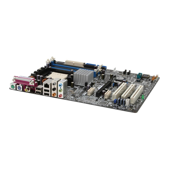
Page 20: Motherboard Layout
Top:Rear Speaker Out Center: Side Speaker Out Below: Center/Subwoofer ATX12V Top:Line In Center:Line Out Bottom:Mic In K8T890 Marvell 88E8053 PWR_FAN PCIEX1_1 A8V-E SE CHA_FAN PCIEX16 SATA2 VT8237R CLRTC CR2032 3V Lithium Cell PCIEX1_2 CMOS Power SATA1 USB56 USB78 PCI1 FP_AUDIO ®... -
Page 21: Central Processing Unit (Cpu)
Locate the CPU socket on the motherboard. A8V-E SE ® A8V-E SE CPU Socket 939 Before installing the CPU, make sure that the socket box is facing towards you and the load lever is on your left. A S U S A 8 V - E S E... - Page 22 Unlock the socket by pressing the lever sideways, then lift it up to a 90 -100 angle. S o c k e t L e v e r S o c k e t L e v e r S o c k e t L e v e r S o c k e t L e v e r S o c k e t L e v e r Make sure that the socket lever is lifted up to 90 -100 angle, otherwise...
-
Page 23: Installing The Heatsink And Fan
1.6.3 1.6.3 1.6.3 Installing the heatsink and fan Installing the heatsink and fan Installing the heatsink and fan 1.6.3 1.6.3 Installing the heatsink and fan Installing the heatsink and fan The AMD Athlon™ 64, AMD Athlon™ 64FX or AMD Athlon™ 64 X2 processors require a specially designed heatsink and fan assembly to ensure optimum thermal condition and performance. - Page 24 Do not forget to connect ® the CPU fan connector! Hardware monitoring errors can occur if you fail to plug A8V-E SE CPU Fan connector this connector. 1 - 1 2 1 - 1 2 1 - 1 2 C h a p t e r 1 : P r o d u c t i n t r o d u c t i o n...
-
Page 25: System Memory
Inline Memory Modules (DIMM) sockets. The following figure illustrates the location of the sockets: A8V-E SE ® A8V-E SE 184-pin DDR DIMM sockets C h a n n e l C h a n n e l C h a n n e l... - Page 26 Table 1 Table 1 Table 1 Table 1 Table 1 Recommended memory configurations Recommended memory configurations Recommended memory configurations Recommended memory configurations Recommended memory configurations S o c k e t s S o c k e t s S o c k e t s S o c k e t s S o c k e t s M o d e...
- Page 27 C C C C C - support for 4 modules inserted into the yellow and black slots as two pairs of Dual-channel memory configuration. Visit the ASUS website (www.asus.com) for the latest DDR400 Qualified Vendors List. A S U S A 8 V - E S E...
-
Page 28: Installing A Dimm
1.7.3 1.7.3 1.7.3 1.7.3 1.7.3 Installing a DIMM Installing a DIMM Installing a DIMM Installing a DIMM Installing a DIMM Make sure to unplug the power supply before adding or removing DIMMs or other system components. Failure to do so may cause severe damage to both the motherboard and the components. -
Page 29: Expansion Slots
Expansion slots In the future, you may need to install expansion cards. The following sub-sections describe the slots and the expansion cards that they support. Make sure to unplug the power cord before adding or removing expansion cards. Failure to do so may cause you physical injury and damage motherboard components. -
Page 30: Interrupt Assignments
1.8.3 1.8.3 1.8.3 Interrupt assignments Interrupt assignments Interrupt assignments 1.8.3 1.8.3 Interrupt assignments Interrupt assignments Standard interrupt assignments Standard interrupt assignments Standard interrupt assignments Standard interrupt assignments Standard interrupt assignments I R Q I R Q I R Q P r i o r i t y P r i o r i t y P r i o r i t y S t a n d a r d F u n c t i o n... -
Page 31: Pci Slots
1.8.4 1.8.4 1.8.4 1.8.4 1.8.4 PCI slots PCI slots PCI slots PCI slots PCI slots The PCI slots support cards such as a LAN card, SCSI card, USB card, and other cards that comply with PCI specifications. The figure shows a LAN card installed on a PCI slot. -
Page 32: Jumpers
Normal Clear CMOS (Default) A8V-E SE Clear RTC RAM You do not need to clear the RTC when the system hangs due to overclocking. For system failure due to overclocking, use the C.P.R. (CPU Parameter Recall) feature. Shut down and reboot the system so the BIOS can automatically reset parameter settings to default values. - Page 33 USBPW78 A8V-E SE USBPW56 ® +5VSB A8V-E SE USB device wake-up (Default) • The USB device wake-up feature requires a power supply that can provide 500mA on the +5VSB lead for each USB port; otherwise, the system would not power up.
-
Page 34: 1.10 Connectors
1.10 Connectors 1.10.1 1.10.1 Rear panel connectors Rear panel connectors 1.10.1 1.10.1 1.10.1 Rear panel connectors Rear panel connectors Rear panel connectors 1 . 1 . P a r a l l e l p o r t . P a r a l l e l p o r t . P a r a l l e l p o r t . -
Page 35: Internal Connectors
DELUXE PIN 1 ® A8V-E SE Floppy disk drive connector A S U S A 8 V - E S E A S U S A 8 V - E S E A S U S A 8 V - E S E... -
Page 36: Jumper Settings
(usually zigzag) on the IDE ribbon cable to PIN 1. ® PIN 1 A8V-E SE IDE connectors 1 - 2 4 1 - 2 4 1 - 2 4 C h a p t e r 1 : P r o d u c t i n t r o d u c t i o n... - Page 37 COM1 A8V-E SE PIN 1 ® A8V-E SE COM port connector The Serial port module is purchased separately. A S U S A 8 V - E S E A S U S A 8 V - E S E...
- Page 38 These connectors allow you to receive stereo audio input from sound sources such as a CD-ROM, TV-tuner, or MPEG card. A8V-E SE ® A8V-E SE Internal audio connectors 1 - 2 6 1 - 2 6 1 - 2 6...
- Page 39 A8V-E SE FP_AUDIO ® A8V-E SE Front panel audio connector A S U S A 8 V - E S E A S U S A 8 V - E S E A S U S A 8 V - E S E...
- Page 40 +5 Volts +5V Standby +5 Volts +12 Volts +5 Volts +12 Volts A8V-E SE ATX power connectors Ground +3 Volts 1 - 2 8 1 - 2 8 1 - 2 8 C h a p t e r 1 : P r o d u c t i n t r o d u c t i o n...
- Page 41 CHASSIS ® (Default) A8V-E SE Chassis alarm lead A S U S A 8 V - E S E A S U S A 8 V - E S E A S U S A 8 V - E S E...
-
Page 42: System Panel Connector
IDE LED RESET ® Requires an ATX power supply. A8V-E SE System panel connector The sytem panel connector is color-coded for easy connection. Refer to the connector description below for details. • S y s t e m p o w e r L E D ( G r e e n 3 - p i n P L E D ) -
Page 43: Chapter 2: Bios Setup
This chapter tells how to change the system settings through the BIOS Setup menus. Detailed descriptions of the BIOS parameters are also provided. BIOS setup A S U S A 8 V - E S E A S U S A 8 V - E S E A S U S A 8 V - E S E 2 - 1 2 - 1... -
Page 44: Managing And Updating Your Bios
Save a copy of the original motherboard BIOS file to a bootable floppy disk in case you need to restore the BIOS in the future. Copy the original motherboard BIOS using the ASUS Update or AwardBIOS Flash utilities. 2.1.1 2.1.1... -
Page 45: Updating The Bios
AwardBIOS Flash Utility. Follow these instructions to update the BIOS using this utility. 1. Download the latest BIOS file from the ASUS web site. Rename the file to A 8 V - E _ S E . B I N A 8 V - E _ S E . - Page 46 Type the BIOS file name AwardBIOS Flash Utility for ASUS V1.01 F i l e N a m e t o F i l e N a m e t o in the F i l e N a m e t o...
-
Page 47: Saving The Current Bios File
To save the current BIOS file using the AwardBIOS Flash Utility: Follow steps 1 to 6 of the previous section. Press <Y> when the AwardBIOS Flash Utility for ASUS V1.01 utility prompts you to (C) Phoenix Technologies Ltd. All Rights Reserved... -
Page 48: Asus Crashfree Bios 2 Utility
ASUS CrashFree BIOS 2 utility ASUS CrashFree BIOS 2 utility The ASUS CrashFree BIOS 2 is an auto recovery tool that allows you to restore the BIOS file when it fails or gets corrupted during the updating process. You can update a corrupted BIOS file using the motherboard support CD or the floppy disk that contains the updated BIOS file. - Page 49 Restart the system after the utility completes the updating process. The recovered BIOS may not be the latest BIOS version for this motherboard. Visit the ASUS website (www.asus.com) to download the latest BIOS file. A S U S A 8 V - E S E...
-
Page 50: Asus Ez Flash Utility
ASUS EZ Flash utility ASUS EZ Flash utility The ASUS EZ Flash feature allows you to update the BIOS without having to go through the long process of booting from a floppy disk and using a DOS-based utility. The EZ Flash utility is built-in the BIOS chip so it is accessible by pressing <Alt>... -
Page 51: Asus Update Utility
ASUS Update utility 2.1.6 2.1.6 ASUS Update utility ASUS Update utility The ASUS Update is a utility that allows you to manage, save, and update the motherboard BIOS in Windows ® environment. The ASUS Update utility allows you to: • Save the current BIOS file •... - Page 52 Updating the BIOS through the Internet Updating the BIOS through the Internet Updating the BIOS through the Internet To update the BIOS through the Internet: Launch the ASUS Update utility from the Windows ® desktop by clicking S t a r t...
- Page 53 A S U S U p d a t e > A S U S U p d a t e A S U S U p d a t e. The ASUS Update main window appears. A S U S U p d a t e...
-
Page 54: Bios Setup Program
The BIOS setup screens shown in this section are for reference purposes only, and may not exactly match what you see on your screen. • Visit the ASUS website (www.asus.com) to download the latest BIOS file for this motherboard and . 2 - 1 2 2 - 1 2... -
Page 55: Bios Menu Screen
• Visit the ASUS website (www.asus.com) to download the latest BIOS information. A S U S A 8 V - E S E A S U S A 8 V - E S E... -
Page 56: Legend Bar
2.2.3 2.2.3 2.2.3 Legend bar Legend bar Legend bar 2.2.3 2.2.3 Legend bar Legend bar At the bottom of the Setup screen is a legend bar. The keys in the legend bar allow you to navigate through the various setup menus. The following table lists the keys found in the legend bar with their corresponding functions. -
Page 57: Pop-Up Window
[1.44M, 3.5 in.] Specifies the capacity Legacy Diskette A: Primary IDE Master [ST321122A] and physical size of Primary IDE Slave [ASUS CDS520/A] diskette drive A. Disabled ..[ ] Secondary IDE Master [None] 360K , 5.25 in..[ ]... -
Page 58: Main Menu
Item Specific Help Legacy Diskette A: [1.44M, 3.5 in.] Change the day, month, Primary IDE Master [ST321122A] year and century. Primary IDE Slave [ASUS CDS520/A] Secondary IDE Master [None] Secondary IDE Slave [None] HDD SMART Monitoring [Disabled] Installed Memory 256MB... -
Page 59: Primary And Secondary Ide Master/Slave
2.3.4 2.3.4 2.3.4 Primary and Secondary IDE Master/Slave Primary and Secondary IDE Master/Slave Primary and Secondary IDE Master/Slave 2.3.4 2.3.4 Primary and Secondary IDE Master/Slave Primary and Secondary IDE Master/Slave While entering Setup, the BIOS automatically detects the presence of IDE devices. -
Page 60: Hdd Smart Monitoring
Capacity Capacity Capacity Capacity Capacity Displays the auto-detected hard disk capacity. This item is not configurable. Cylinder Cylinder Cylinder Cylinder Cylinder Shows the number of the hard disk cylinders. This item is not configurable. H e a d H e a d H e a d H e a d H e a d... -
Page 61: Advanced Menu
Advanced menu The Advanced menu items allow you to change the settings for the CPU and other system devices. Take caution when changing the settings of the Advanced menu items. Incorrect field values can cause the system to malfunction. Phoenix-Award BIOS CMOS Setup Utility Main Advanced Power... - Page 62 Spread Spectrum [Auto] Enables or disables the clock generator spread spectrum. Configuration options: [Disabled] [Enabled] [Auto] PCIEx clock Sync. to CPU [Enable] Enables or disables the PCI Express™ synchronous clock to the CPU. Configuration options: [Disabled] [Enabled] PCIEx Clock [XXX] (value is auto-detected) Allows you to set the PCI Express clock frequency.
-
Page 63: Lan Cable Status
Hammer Vid control [Startup] Hammer Vid control [Startup] Hammer Vid control [Startup] Hammer Vid control [Startup] Hammer Vid control [Startup] Sets the Hammer Voltage ID control. Configuration options: [Startup] [1.5625v] [1.550 v] [1.5375v] [1.525 v] [1.5125v] [1.500 v] [1.4875v] [1.475 v] [1.4625v] [1.450 v] [1.4375v] [1.425 v] [1.4125v] [1.400 v] [1.3875v] [1.375 v] [1.3625v] [1.350 v] [1.3375v] [1.325 v] [1.3125v] [1.300 v] [1.2875v] [1.275 v] [1.2625v] [1.250 v] [1.2375v] [1.225 v] [1.2125v] [1.200 v] [1.1875v] [1.175 v] [1.1625v] [1.150 v] [1.1375v]... -
Page 64: Peg Link Mode
This feature requires the AMD CPU heatsink and fan assembly with monitor chip. If you purchased a separate heatsink and fan package, use the ASUS Q-Fan Technology feature to automatically adjust the CPU fan speed according to your system loading. - Page 65 DRAM Configuration DRAM Configuration DRAM Configuration DRAM Configuration DRAM Configuration The items in this sub-menu show the DRAM-related information auto-detected by the BIOS. Phoenix-Award BIOS CMOS Setup Utility Advanced DRAM Configuration Select Menu Current DRAM Frequency 200 MHz Item Specific Help Timing Mode [Auto] x Memclock index value (MHz)
- Page 66 Row precharge Time (Trp) [Auto] Sets the Row precharge time. Configuration options: [2] [3] [4] [5] [6] [7] 1T/2T Memory Timing [2T] Sets the memory timing. Configuration options: [1T] [2T] H/W DRAM Over 4G Remapping [Enabled] Enables or disables the hardware DRAM remapping when using 4G of system memory.
-
Page 67: Pci Pnp
PEG Data Scrambling [Auto] PEG Data Scrambling [Auto] PEG Data Scrambling [Auto] PEG Data Scrambling [Auto] PEG Data Scrambling [Auto] Disables or enables the PCI Express™ graphics data scrambling. Configuration options: [Auto] [Disable] [Enable] PE0-PE3 Data Scrambling [Enable] PE0-PE3 Data Scrambling [Enable] PE0-PE3 Data Scrambling [Enable] PE0-PE3 Data Scrambling [Enable] PE0-PE3 Data Scrambling [Enable]... - Page 68 IRQ Resources IRQ Resources IRQ Resources IRQ Resources IRQ Resources This sub-menu is activated only when the R e s o u r c e s C o n t r o l l e d B y R e s o u r c e s C o n t r o l l e d B y R e s o u r c e s C o n t r o l l e d B y R e s o u r c e s C o n t r o l l e d B y R e s o u r c e s C o n t r o l l e d B y...
-
Page 69: Onboard Devices Configuration
2.4.7 2.4.7 2.4.7 Onboard Devices Configuration Onboard Devices Configuration Onboard Devices Configuration 2.4.7 2.4.7 Onboard Devices Configuration Onboard Devices Configuration Phoenix-Award BIOS CMOS Setup Utility Advanced Onboard Device Configuration Select Menu Onboard PCIE GbE LAN [Enabled] Item Specific Help Onboard LAN Boot ROM [Disabled] OnChip SATA [Enabled]... -
Page 70: Usb Configuration
Parallel Port Address [378/IRQ7] Parallel Port Address [378/IRQ7] Parallel Port Address [378/IRQ7] Parallel Port Address [378/IRQ7] Parallel Port Address [378/IRQ7] Allows you to select the Parallel Port base addresses. Configuration options: [Disabled] [378/IRQ7] [278/IRQ5] [3BC/IRQ7] Parallel Port Mode [ECP+EPP] Parallel Port Mode [ECP+EPP] Parallel Port Mode [ECP+EPP] Parallel Port Mode [ECP+EPP] Parallel Port Mode [ECP+EPP]... -
Page 71: Power Menu
USB 2.0 Controller [Enabled] USB 2.0 Controller [Enabled] USB 2.0 Controller [Enabled] USB 2.0 Controller [Enabled] USB 2.0 Controller [Enabled] Allows you to enable or disable the USB 2.0 controller. Configuration options: [Disabled] [Enabled] USB Legacy Support [Auto] USB Legacy Support [Auto] USB Legacy Support [Auto] USB Legacy Support [Auto] USB Legacy Support [Auto]... -
Page 72: Apm Configuration
2.5.3 2.5.3 2.5.3 APM Configuration APM Configuration APM Configuration 2.5.3 2.5.3 APM Configuration APM Configuration Phoenix-Award BIOS CMOS Setup Utility Power APM Configuration Select Menu PS2KB Wakeup from S5 [Disabled] Item Specific Help PS2MS Wakeup from S5 [Disabled] USB Resume from [Disabled] When Select Password, Power Up On PCI Devices... - Page 73 Date (of Month) [0] Date (of Month) [0] Date (of Month) [0] Date (of Month) [0] Date (of Month) [0] To set the date of alarm, highlight this item and press <Enter> to display the Day of Month Alarm pop-up menu. Key-in a value within the specified range then press <Enter>.
-
Page 74: Hardware Monitor
Q-FAN Function [Disabled] Q-FAN Function [Disabled] Q-FAN Function [Disabled] Q-FAN Function [Disabled] Allows you to disable or enable the ASUS Q-Fan function. Configuration options: [Disabled] [Enabled] 2 - 3 2 2 - 3 2 C h a p t e r 2 : B I O S s e t u p... -
Page 75: Boot Menu
CPU Target Temperature [xxxºC/xxxºF] CPU Target Temperature [xxxºC/xxxºF] CPU Target Temperature [xxxºC/xxxºF] CPU Target Temperature [xxxºC/xxxºF] CPU Target Temperature [xxxºC/xxxºF] Allows you to set the CPU Q-Fan temperature threshold when the CPU fan speed is increased to lower the CPU temperature. Configuration options: [10ºC/50ºF] [15ºC/59ºF] [20ºC/68ºF] [25ºC/77ºF] [30ºC/86ºF] [35ºC/95ºF] [40ºC/104ºF] [45ºC/113ºF] [50ºC/122ºF] [55ºC/131ºF] [60ºC/140ºF] [65ºC/149ºF] [70ºC/158ºF] [75ºC/167ºF]... -
Page 76: Boot Device Priority
2.6.1 2.6.1 Boot Device Priority Boot Device Priority 2.6.1 2.6.1 2.6.1 Boot Device Priority Boot Device Priority Boot Device Priority Phoenix-Award BIOS CMOS Setup Utility Power Boot Device Priority Select Menu 1st Boot Device [Removable] Item Specific Help 2nd Boot Device [Hard Disk] 3rd Boot Device [CDROM]... -
Page 77: Cdrom Drives
2.6.4 2.6.4 2.6.4 2.6.4 2.6.4 CDROM Drives CDROM Drives CDROM Drives CDROM Drives CDROM Drives Phoenix-Award BIOS CMOS Setup Utility Boot CDROM Drives Select Menu 1. 1st Slave: XXXXXXXXX Item Specific Help 1. 1st Slave: XXXXXXXXX 1. 1st Slave: XXXXXXXXX 1. - Page 78 Allows you to enable or disable the full screen logo display feature. Configuration options: [Disabled] [Enabled] Make sure that the above item is set to [Enabled] if you want to use the ASUS MyLogo2™ feature. Halt On [All, But Keyboard] Halt On [All, But Keyboard]...
-
Page 79: Security
2.6.6 2.6.6 2.6.6 2.6.6 2.6.6 Security Security Security Security Security Phoenix-Award BIOS CMOS Setup Utility Boot Boot Settings Configuration Select Menu Supervisor Password Clear Item Specific Help User Password Clear Password Check [Setup] Supervisor password controls full access, <Enter> to change password. -
Page 80: Exit Menu
Password Check Password Check Password Check Password Check Password Check This field requires you to enter the password before entering the BIOS setup or the system. Select [Setup] to require the password before entering the BIOS Setup. Select [System] to require the password before entering the system. - Page 81 Exit & Discard Changes Exit & Discard Changes Exit & Discard Changes Exit & Discard Changes Exit & Discard Changes Select this option only if you do not want to save the changes that you made to the Setup program. If you made changes to fields other than System Date, System Time, and Password, the BIOS asks for a confirmation before exiting.
- Page 82 2 - 4 0 2 - 4 0 C h a p t e r 2 : B I O S s e t u p C h a p t e r 2 : B I O S s e t u p 2 - 4 0 2 - 4 0 2 - 4 0...
-
Page 83: Chapter 3: Software Support
This chapter describes the contents of the support CD that comes with the motherboard package. Software support A S U S A 8 V - E S E A S U S A 8 V - E S E A S U S A 8 V - E S E 3 - 1 3 - 1 3 - 1... -
Page 84: Installing An Operating System
The support CD that came with the motherboard package contains the drivers, software applications, and utilities that you can install to avail all motherboard features. The contents of the support CD are subject to change at any time without notice. Visit the ASUS website(www.asus.com) for updates. 3.2.1 3.2.1 3.2.1... -
Page 85: Drivers Menu
3.2.2 3.2.2 3.2.2 3.2.2 3.2.2 Drivers menu Drivers menu Drivers menu Drivers menu Drivers menu The drivers menu shows the available device drivers if the system detects installed devices. Install the necessary drivers to activate the devices. VIA 4 in 1 drivers VIA 4 in 1 drivers VIA 4 in 1 drivers VIA 4 in 1 drivers... -
Page 86: Utilities Menu
ASUS Update ASUS Update ASUS Update Allows you to download the latest version of the BIOS from the ASUS website. Before using the ASUS Update, make sure that you have an Internet connection so you can connect to the ASUS website. -
Page 87: Asus Contact Information
Click the C o n t a c t C o n t a c t C o n t a c t tab to display the ASUS contact information. You can C o n t a c t C o n t a c t also find this information on the inside front cover of this user guide. - Page 88 3 - 6 3 - 6 3 - 6 C h a p t e r 3 : S o f t w a r e s u p p o r t C h a p t e r 3 : S o f t w a r e s u p p o r t C h a p t e r 3 : S o f t w a r e s u p p o r t 3 - 6 3 - 6...