Table of Contents
Advertisement
Advertisement
Table of Contents

Related Manuals for Asus A8V-VM SE


Summary of Contents for Asus A8V-VM SE
- Page 1 A8V-VM SE...
- Page 2 Product warranty or service will not be extended if: (1) the product is repaired, modified or altered, unless such repair, modification of alteration is authorized in writing by ASUS; or (2) the serial number of the product is defaced or missing.
-
Page 3: Table Of Contents
Table of contents Notices ....................vi Safety information ................vii A8V-VM SE specifications summary ............. x Chapter 1: Product introduction Welcome! ................1-2 Package contents ..............1-2 Special features ..............1-3 1.3.1 Product highlights ........... 1-3 1.3.2 Innovative ASUS features ........1-4 Before you proceed .............. - Page 4 Creating a bootable floppy disk ......2-2 2.1.2 ASUS EZ Flash utility ..........2-3 2.1.3 AFUDOS utility ............2-4 2.1.4 ASUS CrashFree BIOS 2 utility ........ 2-6 2.1.5 ASUS Update utility ..........2-8 BIOS setup program ............2-11 2.2.1 BIOS menu screen ..........2-12 2.2.2...
- Page 5 Installing an operating system ..........3-2 Support CD information ............3-2 3.2.1 Running the support CD .......... 3-2 3.2.2 Drivers menu ............3-3 3.2.3 Utilities menu ............3-4 3.2.4 Make disk menu ............3-5 3.2.4 Manual ..............3-6 3.2.5 ASUS Contact information ........3-6...
-
Page 6: Notices
Notices Federal Communications Commission Statement This device complies with Part 15 of the FCC Rules. Operation is subject to the following two conditions: • This device may not cause harmful interference, and • This device must accept any interference received including interference that may cause undesired operation. -
Page 7: Safety Information
Safety information Electrical safety • To prevent electrical shock hazard, disconnect the power cable from the electrical outlet before relocating the system. • When adding or removing devices to or from the system, ensure that the power cables for the devices are unplugged before the signal cables are connected. -
Page 8: About This Guide
Refer to the following sources for additional information and for product and software updates. ASUS websites The ASUS website provides updated information on ASUS hardware and software products. Refer to the ASUS contact information. Optional documentation Your product package may include optional documentation, such as warranty flyers, that may have been added by your dealer. -
Page 9: Conventions Used In This Guide
Conventions used in this guide To make sure that you perform certain tasks properly, take note of the following symbols used throughout this manual. DANGER/WARNING: Information to prevent injury to yourself when trying to complete a task. CAUTION: Information to prevent damage to the components when trying to complete a task. -
Page 10: A8V-Vm Se Specifications Summary
A8V-VM SE specifications summary Socket 939 for AMD Athlon™ 64/Sempron™/Opteron™ ® processors Supports AMD 64 architecture that enables simultaneous 32-bit and 64-bit computing Supports AMD Cool ‘n’ Quiet!™ Technology Northbridge: VIA K8M890 ® Chipset Southbridge: VIA VT8237A ® 1GH/z System Bus... - Page 11 A8V-VM SE specifications summary Internal I/O 1 x 24-pin ATX power connector connectors 1 x 4-pin ATX 12V power connector 2 x USB connectors for four additional USB 2.0 ports 1 x Front panel audio connector CPU/Chassis fan connectors 1 x CD audio-in connector...
- Page 13 This chapter describes the motherboard features and the new technologies it supports. Product introduction...
-
Page 14: Welcome
® The motherboard delivers a host of new features and latest technologies, making it another standout in the long line of ASUS quality motherboards! Before you start installing the motherboard, and hardware devices on it, check the items in your package with the list below. -
Page 15: Special Features
12 Mbps bandwidth on USB 1.1 to a fast 480 Mbps on USB 2.0. USB 2.0 is backward compatible with USB 1.1. See pages 1-20, 1-22, and 2-26 for details. ASUS A8V-VM SE... -
Page 16: Innovative Asus Features
ASUS EZ Flash BIOS With the ASUS EZ Flash, you can easily update the system BIOS even before loading the operating system. No need to use a DOS-based utility or boot from a floppy disk. See page 2-3 for details. -
Page 17: Before You Proceed
OFF. Unplug the power cable from the power outlet and make sure that the standby power LED is OFF before installing any system component. SB_PWR A8V-VM SE Standby Powere d Power A8V-VM SE Onboard LED ASUS A8V-VM SE... -
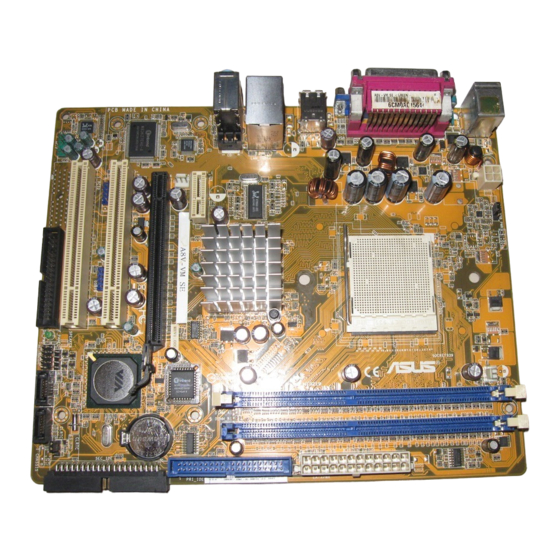
Page 18: Motherboard Overview
Place six (6) screws into the holes indicated by circles to secure the motherboard to the chassis. Do not overtighten the screws! Doing so can damage the motherboard. Place this side towards the rear of the chassis A8V-VM SE Chapter 1: Product introduction... - Page 19 USB4 K8M890 Top:Line In Center:Line Out Below:Mic In PCIEX1_1 A8V-VM SE BIOS RTL8201CL PCIEX16 CR2032 3V Lithium Cell CMOS Power Super I/O PCI1 VT8237A USB56_WFG USB78 USB56 PCI2 ALC660 SPEAKER AAFP CLRTC SATA1 SATA2 F_PANEL FLOPPY SB_PWR ASUS A8V-VM SE...
-
Page 20: Central Processing Unit (Cpu)
To install a CPU: Locate the CPU socket on the motherboard. A8V-VM SE A8V-VM SE CPU Socket 939 Before installing the CPU, make sure that the socket box is facing towards you and the load lever is on your left. - Page 21 CPU! When the CPU is in place, push down the socket lever to secure the CPU. The lever clicks on the side tab to indicate that it is locked. ASUS A8V-VM SE...
-
Page 22: Installing The Heatsink And Fan
1.6.3 Installing the heatsink and fan The AMD Athlon™ 64, AMD Sempron™, or AMD Opteron™ processor AMD Opteron™ processor Opteron™ processor requires a specially designed heatsink and fan assembly to ensure optimum thermal condition and performance. Follow these steps to install the CPU heatsink and fan. Place the heatsink on top of the installed CPU, making sure that the heatsink fits properly on the retention module base. - Page 23 CPU_FAN. CPU_FAN Do not forget to connect the A8V-VM SE CPU fan connector! Hardware monitoring errors can occur if you fail to plug this A8V-VM SE CPU Fan Connector connector. ASUS A8V-VM SE 1-11...
-
Page 24: System Memory
1.7.1 Overview The motherboard comes with two 184-pin Double Data Rate (DDR) Dual Inline Memory Module (DIMM) sockets. The following figure illustrates the location of the sockets: A8V-VM SE A8V-VM SE 184-pin DDR DIMM Sockets Channel Sockets Channel A DIMM_A1... - Page 25 256MB Kingmax MPXB62D-38KT3R Kingmax KDL388P4LA-50 • • 512MB Kingmax MPXC22D-38KT3R Kingmax KDL388P4EA-50 • • 256MB Vdata MDYVD6F4G2880B1E0H Vdata VDD9616A8A-5C • • 256MB 3208GATA07-04A7 PM4D328D50406EU • • 512MB 3208GATA01-04A4 PM4D328S50403DU • • (Continued on the next page) ASUS A8V-VM SE 1-13...
- Page 26 - supports one module as a single-channel memory configuration. supports one pair of modules inserted into two slots as one pair of dual-channel memory configuration. Visit the ASUS website (www.asus.com) for the latest DDR 400 Qualified Vendors List. 1-14 Chapter 1: Product introduction...
-
Page 27: Installing A Dimm
DIMM. DDR DIMM notch Support the DIMM lightly with your fingers when pressing the retaining clips. The DIMM might get damaged when it flips out with extra force. Remove the DIMM from the socket. ASUS A8V-VM SE 1-15... -
Page 28: Expansion Slots
Expansion slots In the future, you may need to install expansion cards. The following sub-sections describe the slots and the expansion cards that they support. Make sure to unplug the power cord before adding or removing expansion cards. Failure to do so may cause you physical injury and damage motherboard components. -
Page 29: Standard Interrupt Assignments
When using PCI cards on shared slots, ensure that the drivers support “Share IRQ” or that the cards do not need IRQ assignments; otherwise, conflicts will arise between the two PCI groups, making the system unstable and the card inoperable. ASUS A8V-VM SE 1-17... -
Page 30: Pci Slots
1.8.3 PCI Express x1 slot This motherboard supports PCI Express x1 network cards, SCSI cards and other cards that comply with the PCI Express specifications. The figure shows a network card installed on the PCI Express x1 slot. 1.8.4 PCI slots The PCI slots support cards such as a LAN card, SCSI card, USB card, and other cards that comply with PCI... -
Page 31: Jumpers
CLRTC A8V-VM SE Normal Clear CMOS (Default) A8V-VM SE Clear RTC RAM Except when clearing the RTC RAM, never remove the cap on CLRTC jumper default position. Removing the cap will cause system boot failure. ASUS A8V-VM SE 1-19... - Page 32 PS2_USB_PWR +5VSB (Default) A8V-VM SE A8V-VM SE USB Device Wake Up • The USB device wake-up feature requires a power supply that can provide 500mA on the +5VSB lead for each USB port; otherwise, the system would not power up.
-
Page 33: 1.10 Connectors
Line Out port (lime). This port connects a headphone or a speaker. In 4-channel and 6-channel configuration, the function of this port becomes Front Speaker Out. Microphone port (pink). This port connects a microphone. ASUS A8V-VM SE 1-21... -
Page 34: 1.10.2 Internal Connectors
Pin 5 on the connector is removed to prevent incorrect cable connection when using a FDD cable with a covered Pin 5. FLOPPY A8V-VM SE PIN 1 NOTE: Orient the red markings on the floppy ribbon cable to PIN 1. A8V-VM SE Floppy Disk Drive Connector 1-22 Chapter 1: Product introduction... - Page 35 • Use the 80-conductor IDE cable for Ultra DMA 133/100/66 IDE devices. If any device jumper is set as “Cable-Select,” make sure all other device jumpers have the same setting. A8V-VM SE A8V-VM SE IDE Connectors ASUS A8V-VM SE 1-23...
- Page 36 RAID manual in the support CD. Speaker out connector (4-pin SPEAKER) This connector is for the case-mounted speaker and allows you to hear system beeps and warnings. SPEAKER A8V-VM SE A8V-VM SE Speaker Out Connector 1-24 Chapter 1: Product introduction...
- Page 37 Do not forget to connect the fan cables to the fan connectors. Insufficient air flow inside the system may damage the motherboard components. These are not jumpers! Do not place jumper caps on the fan connectors! CPU_FAN CHA_FAN A8V-VM SE +12V Tachometer A8V-VM SE Fan Connectors ASUS A8V-VM SE 1-25...
- Page 38 USB 2.0 specification that supports up to 480 Mbps connection speed. USB56_WFG USB78 USB56 A8V-VM SE A8V-VM SE USB2.0 Connectors Never connect a 1394 cable to the USB connectors. Doing so will damage the motherboard! The USB2.0 module is purchased separately . 1-26 Chapter 1: Product introduction...
- Page 39 +3 Volts -12 Volt s +3 Volts +3 Volts A8V-VM SE ATX Power Connectors • We recommend that you use an ATX 12 V Specification 2.0-compliant power supply unit (PSU) with a minimum of 300 W power rating. This PSU type has 24-pin and 4-pin power plugs.
- Page 40 High Definition Audio. Connect one end of the front panel audio I/O module cable to this connector. FP_AUDIO A8V-VM SE A8V-VM SE Front Panel Audio Connector • We recommend that you connect a high-definition front panel audio module to this connector to avail of the motherboard high- definition audio capability.
-
Page 41: System Panel Connector
This connector supports several system chassis-mounted functions. PLED PWRSW F_PANEL A8V-VM SE HD LED RESET A8V-VM SE System Panel Connector The system panel connector is color-coded for easy connection. Refer to the connector description below for details. • System power LED (Green 2-pin PLED) This 2-pin connector is for the system power LED. - Page 42 1-30 Chapter 1: Product introduction...
- Page 43 This chapter tells how to change the system settings through the BIOS Setup menus. Detailed descriptions of the BIOS parameters are also provided. BIOS setup...
-
Page 44: Managing And Updating Your Bios
The following utilities allow you to manage and update the motherboard Basic Input/Output System (BIOS) setup. ASUS EZ Flash (Updates the BIOS using a floppy disk during POST.) ASUS AFUDOS (Updates the BIOS in DOS mode using a bootable floppy disk.) -
Page 45: Asus Ez Flash Utility
2.1.2 ASUS EZ Flash utility The ASUS EZ Flash feature allows you to update the BIOS without having to go through the long process of booting from a floppy disk and using a DOS-based utility. The EZ Flash utility is built-in the BIOS chip so it is accessible by pressing <Alt>... -
Page 46: Afudos Utility
Updating the BIOS file To update the BIOS file using the AFUDOS utility: Visit the ASUS website (www.asus.com) and download the latest BIOS file for the motherboard. Save the BIOS file to a bootable floppy disk. Chapter 2: BIOS setup... - Page 47 WARNING!! Do not turn off power during flash BIOS Reading file ..done Erasing flash ..done Search bootblock version: 100% Advance Check ..Erasing flash ..done Writing flash ..done Verifying flash ... done Please restart your computer ASUS A8V-VM SE...
-
Page 48: Asus Crashfree Bios 2 Utility
2.1.4 ASUS CrashFree BIOS 2 utility The ASUS CrashFree BIOS 2 is an auto recovery tool that allows you to restore the BIOS file when it fails or gets corrupted during the updating process. You can update a corrupted BIOS file using the motherboard support CD or the floppy disk that contains the updated BIOS file. -
Page 49: Recovering The Bios From The Support Cd
Restart the system after the utility completes the updating process. The recovered BIOS may not be the latest BIOS version for this motherboard. Visit the ASUS website (www.asus.com) to download the latest BIOS file. ASUS A8V-VM SE... -
Page 50: Asus Update Utility
2.1.5 ASUS Update utility The ASUS Update is a utility that allows you to manage, save, and update the motherboard BIOS in Windows environment. The ASUS Update utility ® allows you to: • Save the current BIOS file • Download the latest BIOS file from the Internet •... -
Page 51: Updating The Bios Through The Internet
To update the BIOS through the Internet: Launch the ASUS Update utility from the Windows desktop by clicking ® Start > Programs > ASUS > ASUSUpdate > ASUSUpdate. The ASUS Update main window appears. Select Update BIOS from Select the ASUS FTP site... -
Page 52: Updating The Bios Through A Bios File
To update the BIOS through a BIOS file: Launch the ASUS Update utility from the Windows desktop by ® clicking Start > Programs > ASUS > ASUSUpdate > ASUSUpdate. The ASUS Update main window appears. Select Update BIOS from a file option from the drop-down menu, then click Next. -
Page 53: Bios Setup Program
The BIOS setup screens shown in this section are for reference purposes only, and may not exactly match what you see on your screen. • Visit the ASUS website (www.asus.com) to download the latest BIOS file for this motherboard. ASUS A8V-VM SE 2-11... -
Page 54: Bios Menu Screen
[1.44M, 3.5 in.] Use [+] or [-] to Primary IDE Master [ST340014A] configure System Time. Primary IDE Slave [Not Detected] Seconday IDE Master [ASUS DVD-E616P2] Secondary IDE Slave [Not Detected] Third IDE Master [Not Detected] Third IDE Slave [Not Detected] ←→... -
Page 55: Menu Items
Press the Up/Down arrow keys or <PageUp> / <PageDown> keys to display the other items on the screen. 2.2.9 General help At the top right corner of the menu screen is a brief description of the selected item. ASUS A8V-VM SE Motherboard 2-13... -
Page 56: Main Menu
[1.44M, 3.5 in.] Use [+] or [-] to Primary IDE Master [ST340014A] configure System Time. Primary IDE Slave [Not Detected] Seconday IDE Master [ASUS DVD-E616P2] Secondary IDE Slave [Not Detected] Third IDE Master [Not Detected] Third IDE Slave [Not Detected] ←→... -
Page 57: Primary, Secondary, Third, Fourth Ide Master/Slave
When set to Disabled, the data transfer from and to the device occurs one sector at a time. Configuration options: [Auto] [Disabled] PIO Mode [Auto] Selects the PIO mode. Configuration options: [Auto] [0] [1] [2] [3] [4] ASUS A8V-VM SE Motherboard 2-15... -
Page 58: Ide Configuration
DMA Mode [Auto] Selects the DMA mode. Configuration options: [Auto] [SWDMA0] [SWDMA1] [SWDMA2] [MWDMA0] [MWDMA1] [MWDMA2] [UDMA0] [UDMA1] [UDMA2] [UDMA3] [UDMA4] [UDMA5] [UDMA6] SMART Monitoring [Auto] Sets the Smart Monitoring, Analysis, and Reporting Technology. Configuration options: [Auto] [Disabled] [Enabled] 32Bit Data Transfer [Enabled] Enables or disables 32-bit data transfer. -
Page 59: System Information
Speed : 2000 MHz Count System Memory Installed Size : 256MB Usable Size : 192MB AMI BIOS Displays the auto-detected BIOS information. Processor Displays the auto-detected CPU specification System Memory Displays the auto-detected system memory. ASUS A8V-VM SE Motherboard 2-17... -
Page 60: Advanced Menu
Advanced menu The Advanced menu items allow you to change the settings for the CPU and other system devices. Take caution when changing the settings of the Advanced menu items. Incorrect field values can cause the system to malfunction. Configure CPU. CPU Configuration Chipset Onboard Devices Configuration... -
Page 61: Chipset
The Chipset menu allows you to change the advanced chipset settings. Select an item then press <Enter> to display the sub-menu. Options for NB NorthBridge Configuration AGP Bridge K8M890 AGP/PCI EXPRESS Configuration SouthBridge VIA VT8237A Configuration HyperTransport Configuration AMD Cool ‘ N’ Quiet Configuration ASUS A8V-VM SE Motherboard 2-19... -
Page 62: Northbridge Configuration
NorthBridge Configuration NorthBridge Chipset Configuration Memory Configuration ECC Configuration Memory CLK : 200 MHz CAS Latency(Tcl) : 2.5 RAS/CAS Delay(Trcd) : 3 CLK Min Active RAS(Tras) : 8 CLK Row Precharge Time(Trp) : 3 CLK RAS/RAS Delay(Trrd) : 2 CLK Row Cycle (Trc) : 11 CLK Row Refresh Cycle(Trfc) - Page 63 The following item appears when the User Config Mode item is set to [Manual]. Read Preamble [9.5ns] Configuration options: [2.0ns] [2.5ns] [3.0ns] [3.5ns] [4.0ns]... [9.5ns] Async Latency [11.0ns] Configuration options: [4.0ns] [5.0ns] [6.0ns]... [11.0ns] CMD-ADDR Timing Mode [2T] Configuration options: [1T] [2T] ASUS A8V-VM SE 2-21...
- Page 64 Bank Interleaving [Auto] Configuration options: [Auto] [Disable] Burst Length [4 Beats] Sets the operating burst length. Configuration options: [8 Beats] [4 Beats] [2 Beats] Hardware Memory Hole [Disabled] Enables or disables the hardware memory hole. Configuration options: [Disabled] [Enabled] DDR Reference Voltage [Auto] Sets the DDR reference voltage.
- Page 65 Allows you to disable or set the onchip VGA frame buffer size.Configuration options: [Disabled] [64MB] [128MB][256MB] Primary Graphics Adapter [PCIE VGA] Allows selection of the graphics controller to use as a primary boot device. Configuration options: [PCI] [PCIE VGA] [Integrated VGA] ASUS A8V-VM SE 2-23...
-
Page 66: Southbridge Configuration
SouthBridge Configuration Serial ATA IDE Controller [IDE] Options LAN Controller [Enabled] LAN BOOTROM [Disabled] Disabled High Definition Audio [Auto] USB 1.1 Ports Configuration [USB 8 Ports] RAID Lagacy USB Support [Enabled] USB 2.0 Ports Enable [Enable] PCI Delay Transaction [Enabled] Serial ATA IDE Controller [IDE] This option allows you to set the Serial ATA IDE controller mode. - Page 67 LDT to AGP Width (Downstream) [16 BIT] Configuration options: [16 BIT] [8 BIT] AMD Cool’N’Quiet Configuration AMD Cool’N’Quiet Configuration Enabled/Disabled Cool 'N'Quiet Cool‘N’Quiet [Disabled] Cool ‘N’ Quiet [Disabled] Enables or disables the AMD Cool ‘n’ Quiet technology feature. Configuration options: [Enabled] [Disabled] ASUS A8V-VM SE 2-25...
-
Page 68: Onboard Devices Configuration
2.4.3 Onboard Devices Configuration Allows BIOS to Select Configure Win627EHF Super IO Chipset Serial Port Base Addresses. Serial Port Address [2F8/IRQ3] Serial Port Mode [Normal] Parallel Port Address [378] Parallel Port Mode [ECP] ECP Mode DMA Channel [DMA3] Parallel Port IRQ [IRQ7] v02.58 (C)Copyright 1985-2004, American Megatrends, Inc. -
Page 69: Pci Pnp
Palette Snooping [Disabled] When set to [Enabled], the palette snooping feature informs the PCI devices that an ISA graphics device is installed in the system so that the latter can function correctly. Configuration options: [Disabled] [Enabled] ASUS A8V-VM SE 2-27... -
Page 70: Power Menu
Power menu The Power menu items allow you to change the settings for the Advanced Configuration and Power Interface (ACPI) and the Advanced Power Management (APM). Select an item then press <Enter> to display the configuration options. ACPI 2.0 Support [No] ACPI APIC Support [Enabled]... -
Page 71: Apm Configuration
1A on the +5VSB lead. Configuration options: [Disabled] [Enabled] Resume On PME# [Disabled] When set to [Enabled], the system enables the PME to generate a wake event while the computer is in Soft-off mode. Configuration options: [Disabled] [Enabled] ASUS A8V-VM SE 2-29... - Page 72 Resume On KBC [Disabled] When set to [Enabled], this parameter allows you to use the PS/2 keyboard to turn on the system. This feature requires an ATX power supply that provides at least 1A on the +5VSB lead. Configuration options: [Disabled] [Enabled] Resume On PS/2 Mouse [Disabled] When set to [Enabled], this parameter allows you to use the PS/2 mouse...
-
Page 73: Hardware Monitor
N/A. Configuration options: [Ignored] [xxxRPM] or [N/A] VCORE Voltage, 3.3V Voltage, 5V Voltage, 12V Voltage The onboard hardware monitor automatically detects the voltage output through the onboard voltage regulators. ASUS A8V-VM SE 2-31... -
Page 74: Boot Menu
2nd Boot Device [PM-ST330620A] 3rd Boot Device [PS-ASUS CD-S360] 1st ~ xxth Boot Device [1st Floppy Drive] These items specify the boot device priority sequence from the available devices. The number of device items that appears on the screen depends on the number of devices installed in the system. -
Page 75: Boot Settings Configuration
This allows you to enable or disable the full screen logo display feature. Configuration options: [Disabled] [Enabled] Set this item to [Enabled] to use the ASUS MyLogo™ feature. Add On ROM Display Mode [Force BIOS] Sets the display mode for option ROM. -
Page 76: Security
Interrupt 19 Capture [Disabled] When set to [Enabled], this function allows the option ROMs to trap Interrupt 19. Configuration options: [Disabled] [Enabled] 2.6.3 Security The Security menu items allow you to change the system security settings. Select an item then press <Enter> to display the configuration options. Security Settings <Enter>... -
Page 77: Change User Password
Change User Password Select this item to set or change the user password. The User Password item on top of the screen shows the default Not Installed. After you set a password, this item shows Installed. ASUS A8V-VM SE 2-35... -
Page 78: Exit Menu
To set a User Password: Select the Change User Password item and press <Enter>. On the password box that appears, type a password composed of at least six letters and/or numbers, then press <Enter>. Confirm the password when prompted. The message “Password Installed” appears after you set your password successfully. -
Page 79: Discard Changes
Setup menus. When you select this option or if you press <F5>, a confirmation window appears. Select Ok to load default values. Select Exit & Save Changes or make other changes before saving the values to the non-volatile RAM. ASUS A8V-VM SE 2-37... - Page 80 2-38 Chapter 2: BIOS setup...
-
Page 81: Chapter 3: Software Support
This chapter describes the contents of the support CD that comes with the motherboard package. Software support... -
Page 82: Installing An Operating System
The contents of the support CD are subject to change at any time without notice. Visit the ASUS website(www.asus.com) for updates. 3.2.1 Running the support CD Place the support CD to the optical drive. -
Page 83: Drivers Menu
Install VIA 4 in 1 drivers. VIA Onboard VGA Driver Installs VIA Onboard VGA Driver. Realtek Audio Driver Installs Realtek Audio Driver. VIA Rhine Family Fast Ethernet Adapter Driver Install VIA Rhine Family Fast Ethernet Adapter driver. USB2.0 Driver Installs USB2.0 Driver. ASUS A8V-VM SE... -
Page 84: Utilities Menu
This utility helps you keep your computer in healthy operating condition. ASUS Update Allows you to download the latest version of the BIOS from the ASUS website. Before using the ASUS Update, make sure that you have an Internet connection so you can connect to the ASUS website. -
Page 85: Make Disk Menu
The anti-virus application scans, identifies, and removes computer viruses. View the online help for detailed information. 3.2.4 Make disk menu The Utilities menu shows you to make a RAID driver disk. VIA RAID Driver Allows you to create a VT8237A 32/64bit RAID driver disk. ASUS A8V-VM SE... -
Page 86: Manual
Allows you to open the VIA8237A SATA quick setup user’s manual. 3.2.6 ASUS Contact information Click the Contact tab to display the ASUS contact information. You can also find this information on the inside front cover of this user guide. Chapter 3: Software support...