Draytek VigorPro 5500 Series User Manual
Vigorpro 5500 series unified security firewall
Hide thumbs
Also See for VigorPro 5500 Series:
- Brochure & specs (2 pages) ,
- Declaration of conformity (1 page) ,
- Quick start manual (54 pages)
Table of Contents
Advertisement
Quick Links
VigorPro 5500 Series
Unified Security Firewall
User's Guide
Version: 3.0
Date: 2007/05/02
Copyright 2007 All rights reserved.
This publication contains information that is protected by copyright. No part may be reproduced, transmitted,
transcribed, stored in a retrieval system, or translated into any language without written permission from the copyright
holders. The scope of delivery and other details are subject to change without prior notice.
Microsoft is a registered trademark of Microsoft Corp.
Windows, Windows 95, 98, Me, NT, 2000, XP and Explorer are trademarks of Microsoft Corp.
Apple and Mac OS are registered trademarks of Apple Computer Inc.
Other products may be trademarks or registered trademarks of their respective manufacturers.
Advertisement
Table of Contents

Related Manuals for Draytek VigorPro 5500 Series


Summary of Contents for Draytek VigorPro 5500 Series
- Page 1 VigorPro 5500 Series Unified Security Firewall User’s Guide Version: 3.0 Date: 2007/05/02 Copyright 2007 All rights reserved. This publication contains information that is protected by copyright. No part may be reproduced, transmitted, transcribed, stored in a retrieval system, or translated into any language without written permission from the copyright holders.
- Page 2 Owner http://www.draytek.com. Firmware & Tools Please consult the DrayTek web site for more information on newest firmware, tools Updates and documents. For more detailed information, please refer to http://www.draytek.com Parts of the anti-virus features are powered by Kaspersky Lab ZAO. For more detailed information, please refer to http://www.kaspersky.com.
-
Page 3: European Community Declarations
No. 26, Fu Shing Road, HuKou County, HsinChu Industrial Park, Hsin-Chu, Taiwan 303 Product: VigorPro 5500 DrayTek Corp. declares that VigorPro 5500 Series is in compliance with the following essential requirements and other relevant provisions of R&TTE Directive 1999/5/EEC. The product conforms to the requirements of Electro-Magnetic Compatibility (EMC) Directive 89/336/EEC by complying with the requirements set forth in EN55022/Class A and EN55024/Class A. -
Page 4: Table Of Contents
Preface ...1 1.1 Web Configuration Buttons Explanation ... 1 1.2 LED Indicators and Connectors ... 1 1.2.1 For VigorPro 5500 ... 2 1.2.2 For VigorPro 5500G... 3 1.2.3 For VigorPro 5500i... 4 1.2.4 For VigorPro 5500Gi... 5 1.3 Hardware Installation ... 7 Configuring Basic Settings ...9 2.1 Changing Password ... - Page 5 3.4.4 Service Type Group... 54 3.4.5 CSM Profile... 55 3.5 Firewall ... 57 3.5.1 Basics for Firewall... 57 3.5.2 General Setup... 60 3.5.3 Filter Setup ... 62 3.5.4 DoS Defense ... 67 3.5.5 URL Content Filter ... 70 3.5.6 Web Content Filter... 72 3.6 Anti-Intrusion ...
- Page 6 3.14.3 Security ... 137 3.14.4 Access Control... 138 3.14.5 WDS... 140 3.14.6 AP Discovery ... 142 3.14.7 Station List ... 143 3.14.8 Station Rate Control ... 144 3.15 VLAN ... 144 3.15.1 Wired VLAN ... 144 3.15.2 Wireless VLAN... 145 3.15.3 VLAN Cross Setup...
- Page 7 5.1 Create a LAN-to-LAN Connection Between Remote Office and Headquarter ...211 5.2 Create a Remote Dial-in User Connection Between the Teleworker and Headquarter... 218 5.3 QoS Setting Example... 222 5.4 LAN – Created by Using NAT ... 225 5.5 Upgrade Firmware for Your Router ... 227 5.6 Request a certificate from a CA server on Windows CA Server ...
-
Page 9: Preface
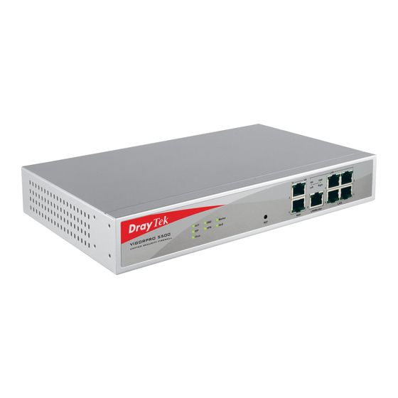
The VigorPro5500 series router provides Dual-WAN interface (which is a configurable second WAN) for Internet access to make the Internet connection more reliable. The wireless LAN supports more secure features and the transmission speed is up to 108Mbps (Super G ). - Page 10 ACT (Activity) Virus IDP (Intrusion Detection and Prevention) Monitor LED on Connector LAN/Monitor Interface (Factory Reset) WAN(1/2) LAN/Monitor LAN (1-4) Status Blinking (Yellow) (Yellow) (left LED) Blinking (right LED) Blinking (left LED) Blinking 1000 (right LED) Blinking Description Restore the default settings. Usage: Turn on the router (ACT LED is blinking).
-
Page 11: For Vigorpro 5500
ACT (Activity) Virus IDP (Intrusion Detection and Prevention) Monitor WLAN LED on Connector LAN/Monitor Interface (Factory Reset) WAN(1/2) LAN/Monitor LAN (1-4) VigorPro5500 Series User’s Guide Status Blinking (Yellow) (Yellow) Blinking (left LED) Blinking (right LED) Blinking (left LED) Blinking 1000 (right LED) Blinking Description... -
Page 12: For Vigorpro 5500I
ACT (Activity) Virus IDP (Intrusion Detection and Prevention) Monitor ISDN LED on Connector LAN/Monitor Interface (Factory Reset) ISDN WAN(1/2) LAN/Monitor LAN (1- 4) Status Blinking On (Yellow) (Yellow) Blinking (left LED) Blinking (right LED) Blinking (left LED) Blinking 1000 (right LED) Blinking Description Restore the default settings. -
Page 13: For Vigorpro 5500Gi
ACT (Activity) Virus IDP (Intrusion Detection and Prevention) Monitor WLAN ISDN LED on Connector LAN/Monitor VigorPro5500 Series User’s Guide Status Blinking On (Yellow) (Yellow) Blinking Blinking (left LED) Blinking (right LED) Blinking (left LED) Blinking 1000 (right LED) Blinking Explanation The router is powered on and running normally. - Page 14 Interface (Factory Reset) ISDN WAN(1/2) LAN/Monitor LAN (1- 4) Description Restore the default settings. Usage: Turn on the router (ACT LED is blinking). Press the hole and keep for more than 5 seconds. When you see the ACT LED begins to blink rapidly than usual, release the button.
-
Page 15: Hardware Installation
This section will guide you to install the router through hardware connection and configure the router’s settings through web browser. Before starting to configure the router, you have to connect your devices correctly. Connect the power cord to the router’s power port on the rear panel, and the other side into a wall outlet. - Page 16 VigorPro5500 Series User’s Guide...
-
Page 17: Configuring Basic Settings
For use the router properly, it is necessary for you to change the password of web configuration for security and adjust primary basic settings. This chapter explains how to setup a password for an administrator and how to adjust basic settings for accessing Internet successfully. - Page 18 Now, the Main Screen will pop up. Note: The home page will change slightly in accordance with the router you have. Go to System Maintenance page and choose Administrator Password. Enter the login password (the default is blank) on the field of Old Password. Type a new one in the field of New Password and retype it on the field of Retype New Password.
-
Page 19: Quick Start Wizard
If your router can be under an environment with high speed NAT, the configuration provide here can help you to deploy and use the router quickly. The first screen of Quick Start Wizard is entering login password. After typing the password, please click Next. On the next page as shown below, please select the WAN interface that you use. -
Page 20: Pppoe
On the next page as shown below, please select the appropriate Internet access type according to the information from your ISP. For example, you should select PPPoE mode if the ISP provides you PPPoE interface. Then click Next for next step. In the Quick Start Wizard, you can configure the router to access the Internet with different protocol/modes such as PPPoE, PPTP, Static IP or DHCP. - Page 21 If your ISP provides you the PPPoE connection, please select PPPoE for this router. The following page will be shown. User Name Password Confirm Password Click Next for viewing summary of such connection. Click Finish. A page of Quick Start Wizard Setup OK!!! will appear. Then, the system status of this protocol will be shown.
-
Page 22: Pptp
Click PPTP as the protocol. Type in all the information that your ISP provides for this protocol. Click Next for viewing summary of such connection. Click Finish. A page of Quick Start Wizard Setup OK!!! will appear. Then, the system status of this protocol will be shown. -
Page 23: Static Ip
Click Static IP as the protocol. Type in all the information that your ISP provides for this protocol. After finishing the settings in this page, click Next to see the following page. Click Finish. A page of Quick Start Wizard Setup OK!!! will appear. Then, the system status of this protocol will be shown. -
Page 24: Dhcp
Click DHCP as the protocol. Type in all the information that your ISP provides for this protocol. After finishing the settings in this page, click Next to see the following page. Click Finish. A page of Quick Start Wizard Setup OK!!! will appear. Then, the system status of this protocol will be shown. -
Page 25: Online Status
The online status shows the system status, WAN status, ADSL Information and other status related to this router within one page. If you select PPPoE/PPTP as the protocol, you will find out a link of Dial PPPoE/PPPoA or Drop PPPoE/PPPoA in the Online Status web page. - Page 26 Online status for DHCP Detailed explanation is shown below: Primary DNS Secondary DNS LAN Status IP Address TX Packets RX Packets WAN1/2 Status Line Name Mode Up Time GW IP TX Packets TX Rate RX Packets RX Rate Note: The words in green mean that the WAN connection of that interface (WAN1/WAN2) is ready for accessing Internet;...
-
Page 27: Saving Configuration
Each time you click OK on the web page for saving the configuration, you can find messages showing the system interaction with you. Ready indicates the system is ready for you to input settings. Settings Saved means your settings are saved once you click Finish or OK button. VigorPro5500 Series User’s Guide... - Page 28 This page is left blank. VigorPro5500 Series User’s Guide...
-
Page 29: Advanced Web Configuration
After finished basic configuration of the router, you can access Internet with ease. For the people who want to adjust more setting for suiting his/her request, please refer to this chapter for getting detailed information about the advanced configuration of this router. As for other examples of application, please refer to chapter 4. -
Page 30: General Setup
Below shows the menu items for WAN. This section will introduce some general settings of Internet and explain the connection modes for WAN1 and WAN2 in details. This router supports dual WAN function. It allows users to access Internet and combine the bandwidth of the dual WAN to speed up the transmission through the network. - Page 31 Physical Type Load Balance Mode Line Speed Active Mode VigorPro5500 Series User’s Guide You can change the physical type for WAN2 or choose Auto negotiation for determined by the system. If you know the practical bandwidth for your WAN interface, please choose the setting of According to Line Speed.
-
Page 32: Internet Access
For the router supports dual WAN function, the users can set different WAN settings (for WAN1/WAN2) for Internet Access. Due to different physical mode for WAN1 and WAN2, the Access Mode for these two connections also varies slightly. Index Display Name Physical Mode Access Mode Details Page... - Page 33 To use PPPoE as the accessing protocol of the internet, please choose Internet Access from WAN menu. Then, select PPPoE mode for WAN2. The following web page will be shown. PPPoE Client Mode ISP Access Setup PPP/MP Setup IP Address Assignment Method (IPCP) VigorPro5500 Series User’s Guide...
- Page 34 After finishing all the settings here, please click OK to activate them. For static IP mode, you usually receive a fixed public IP address or a public subnet, namely multiple public IP addresses from your DSL or Cable ISP service providers. In most cases, a Cable service provider will offer a fixed public IP, while a DSL service provider will offer a public subnet.
- Page 35 Static or Dynamic IP (DHCP Client) Keep WAN Connection RIP Protocol WAN IP Network Settings VigorPro5500 Series User’s Guide Click Enable for activating this function. If you click Disable, this function will be closed and all the settings that you adjusted in this page will be invalid.
- Page 36 DNS Server IP Address Obtain an IP address automatically – Click this button to obtain the IP address automatically if you want to use Dynamic IP mode. Router Name: Type in the router name provided by ISP. Domain Name: Type in the domain name that you have assigned. Specify an IP address –...
- Page 37 To use PPTP as the accessing protocol of the internet, please choose Internet Access from WAN menu. Then, select PPTP mode for WAN2. The following web page will be shown. PPTP Setup ISP Access Setup PPP Setup IP Address Assignment Method(IPCP) VigorPro5500 Series User’s Guide PPTP Link - Click Enable to enable a PPTP client to establish a...
-
Page 38: Load-Balance Policy
WAN IP Network Settings This router supports the function of load balancing. It can assign traffic with protocol type, IP address for specific host, a subnet of hosts, and port range to be allocated in WAN1 or WAN2 interface. The user can assign traffic category and force it to go to dedicate network interface based on the following web page setup. - Page 39 Index Enable Protocol Src IP Start Src IP End Dest IP Start Dest IP End Dest Port Start Dest Port End Click Index 1 to access into the following page for configuring load-balance policy. VigorPro5500 Series User’s Guide Click the number of index to access into the load-balance policy configuration web page.
- Page 40 Enable Protocol Binding WAN interface Src IP Start Src IP End Dest IP Start Dest IP End Dest Port Start Dest Port End Check this box to enable this policy. Use the drop-down menu to choose a proper protocol for the WAN interface.
-
Page 41: Lan
Local Area Network (LAN) is a group of subnets regulated and ruled by router. The design of network structure is related to what type of public IP addresses coming from your ISP. The most generic function of Vigor router is NAT. It creates a private subnet of your own. As mentioned previously, the router will talk to other public hosts on the Internet by using public IP address and talking to local hosts by using its private IP address. - Page 42 Vigor router will exchange routing information with neighboring routers using the RIP to accomplish IP routing. This allows users to change the information of the router such as IP address and the routers will automatically inform for each other. When you have several subnets in your LAN, sometimes a more effective and quicker way for connection is the Static routes function rather than other method.
-
Page 43: General Setup
This page provides you the general settings for LAN. Click LAN to open the LAN settings page and choose General Setup. 1st IP Address 1st Subnet Mask For IP Routing Usage Click Enable to invoke this function. The default setting is IP Address Subnet Mask DHCP Server... - Page 44 RIP Protocol Control DHCP Server Configuration Start IP Address: Enter a value of the IP address pool for the DHCP server to start with when issuing IP addresses. If the 2nd IP address of your router is 220.135.240.1, the starting IP address must be 220.135.240.2 or greater, but smaller than 220.135.240.254.
-
Page 45: Static Route
DNS Server Configuration There are two common scenarios of LAN settings that stated in Chapter 4. For the configuration examples, please refer to that chapter to get more information for your necessity. Go to LAN to open setting page and choose Static Route. Index VigorPro5500 Series User’s Guide DHCP Server IP Address for Relay Agent - Set the IP address of... - Page 46 Destination Address Status Viewing Routing Table Displays the routing table for your reference. Here is an example of setting Static Route in Main Router so that user A and B locating in different subnet can talk to each other via the router. Assuming the Internet access has been configured and the router works properly: use the Main Router to surf the Internet.
- Page 47 Note: There are two reasons that we have to apply RIP Protocol Control on 1st Subnet. The first is that the LAN interface can exchange RIP packets with the neighboring routers via the 1st subnet (192.168.1.0/24). The second is that those hosts on the internal private subnets (ex.
-
Page 48: Vlan
Note: This menu is available for Vigor5500 model. For Vigor5500G, please refer to 3.13. Virtual LAN function provides you a very convenient way to manage hosts by grouping them based on the physical port. You can also manage the in/out rate of each port. Go to LAN page and select VLAN. -
Page 49: Bind Ip To Mac
After checking the box to enable VLAN function, you will check the table according to the needs as shown below. To remove VLAN, uncheck the needed box and click OK to save the results. This function is used to bind the IP and MAC address in LAN to have a strengthen control in network. -
Page 50: Nat
Add and Edit Refresh IP Bind List Edit Delete Note: Before you select Strict Bind, you have to bind one set of IP/MAC address for one PC. If not, no one of the PCs can access into Internet. And the web configurator of the router might not be accessed. -
Page 51: Port Redirection
Below shows the menu items for NAT. Port Redirection is usually set up for server related service inside the local network (LAN), such as web servers, FTP servers, E-mail servers etc. Most of the case, you need a public IP address for each server and this public IP address/domain name are recognized by all users. - Page 52 Press any number under Index to access into next page for configuring port redirection. Enable Mode Service Name Protocol Public Port Private IP Check this box to enable such port redirection setting. Two options (Single and Range) are provided here for you to choose.
- Page 53 Private Port Active Note that the router has its own built-in services (servers) such as Telnet, HTTP and FTP etc. Since the common port numbers of these services (servers) are all the same, you may need to reset the router in order to avoid confliction. For example, the built-in web configurator in the router is with default port 80, which may conflict with the web server in the local network, http://192.168.1.13:80.
-
Page 54: Dmz Host
As mentioned above, Port Redirection can redirect incoming TCP/UDP or other traffic on particular ports to the specific private IP address/port of host in the LAN. However, other IP protocols, for example Protocols 50 (ESP) and 51 (AH), do not travel on a fixed port. Vigor router provides a facility DMZ Host that maps ALL unsolicited data on any protocol to a single host in the LAN. - Page 55 If you previously have set up WAN Alias in Internet Access>>PPPoE, you will find them in Aux. WAN IP list for your selection. Enable Private IP Choose PC VigorPro5500 Series User’s Guide Check to enable the DMZ Host function. Enter the private IP address of the DMZ host, or click Choose PC to select one.
-
Page 56: Open Ports
Open Ports allows you to open a range of ports for the traffic of special applications. Common application of Open Ports includes P2P application (e.g., BT, KaZaA, Gnutella, WinMX, eMule and others), Internet Camera etc. Ensure that you keep the application involved up-to-date to avoid falling victim to any security exploits. - Page 57 Enable Open Ports Comment WAN Interface Local Computer Choose PC Protocol Start Port End Port VigorPro5500 Series User’s Guide Check to enable this entry. Make a name for the defined network application/service. Specify the WAN interface that will be used for this entry. Enter the private IP address of the local host or click Choose PC to select one.
-
Page 58: Objects Settings
For IPs in a range and service ports in a limited range usually will be applied for configuring router’s settings, therefore we can define them with objects and bind them with groups for using conveniently. Later, we can select that object/group that can apply it. For example, all the IPs in the same department can be defined with an IP object (a range of IP address). - Page 59 Name Interface Address Type Start IP Address End IP Address Subnet Mask Invert Select Below is an example of IP objects settings. VigorPro5500 Series User’s Guide Type a name for this profile. Maximum 15 characters are allowed. Choose a proper interface (WAN, LAN or Any). For example, the Direction setting in Edit Filter Rule will ask you specify IP or IP range for WAN or LAN or any IP address.
-
Page 60: Ip Group
This page allows you to bind several IP objects into one IP group. Set to Factory Default Click the number under Index column for settings in detail. Name Interface Available IP Objects Selected IP Objects Clear all profiles. Type a name for this profile. Maximum 15 characters are allowed. -
Page 61: Service Type Object
You can set up to 96 sets of Service Type Objects with different conditions. Set to Factory Default Click the number under Index column for settings in detail. Name Protocol Source/Destination Port VigorPro5500 Series User’s Guide Clear all profiles. Type a name for this profile. Specify the protocol(s) which this profile will apply to. -
Page 62: Service Type Group
Below is an example of service type objects settings. This page allows you to bind several service types into one group. Set to Factory Default Click the number under Index column for settings in detail. (!=) – when the first and last value are the same, all the ports except the port defined here;... -
Page 63: Csm Profile
Name Available Service Type Objects Selected Service Type Objects You can define policy profiles for different policy of IM (Instant Messenger)/P2P (Peer to Peer) application. CSM profile can be used in Filter Setup page. Set to Factory Default Click the number under Index column for settings in detail. VigorPro5500 Series User’s Guide Type a name for this profile. - Page 64 Profile Name Type a name for the CSM profile. There are several items for IM, VoIP, P2P provided here for you to choose to disallow people using. Simple check the box (es) and then click OK. Later, in the Firewall>>Edit Filter Set>>Edit Filter Rule page, you can use Content Management drop down list to choose the proper CSM profile as the standard for the host(s) to follow.
-
Page 65: Firewall
While the broadband users demand more bandwidth for multimedia, interactive applications, or distance learning, security has been always the most concerned. The firewall of the Vigor router helps to protect your local network against attack from unauthorized outsiders. It also restricts users in the local network from accessing the Internet. - Page 66 Depending on whether there is an existing Internet connection, or in other words “the WAN link status is up or down”, the IP filter architecture categorizes traffic into two: Call Filter and Data Filter. Call Filter - When there is no existing Internet connection, Call Filter is applied to all traffic, all of which should be outgoing.
- Page 67 As the popularity of all kinds of instant messenger application arises, communication cannot become much easier. Nevertheless, while some industry may leverage this as a great tool to connect with their customers, some industry may take reserve attitude in order to reduce employee misusage during office hour or prevent unknown security leak.
-
Page 68: General Setup
We all know that the content on the Internet just like other types of media may be inappropriate sometimes. As a responsible parent or employer, you should protect those in your trust against the hazards. With Web filtering service of the Vigor router, you can protect your business from common primary threats, such as productivity, legal liability, network and security threats. - Page 69 For troubleshooting needs you can specify the filter/CSM/Anti-Virus/Anti-Intrusion/Anti-Spam log here by checking the box. Check this box to record all packets; or uncheck this box to ignore all the packet record. The log will be displayed on Draytek Syslog window.
-
Page 70: Filter Setup
Some on-line games (for example: Half Life) will use lots of fragmented UDP packets to transfer game data. Instinctively as a secure firewall, Vigor router will reject these fragmented packets to prevent attack unless you enable “Accept Incoming Fragmented UDP Packets”. By checking this box, you can play these kinds of on-line games. If security concern is in higher priority, you cannot enable “Accept Incoming Fragmented UDP Packets”. - Page 71 Check to enable the Filter Rule Comments Index (1-15) Direction Source/Destination IP Click Edit to access into the following dialog to choose the VigorPro5500 Series User’s Guide Check this box to enable the filter rule. Enter filter set comments/description. Maximum length is 14- character long.
- Page 72 To set the IP address manually, please choose Any Address/Single Address/Range Address/Subnet Address as the Address Type and type them in this dialog. In addition, if you want to use the IP range from defined groups or objects, please choose Group and Objects as the Address Type.
- Page 73 Check this box to record all packets; or uncheck this box to ignore all the packet record. The log will be displayed on Draytek Syslog window. All the packets/connections within the range configured in the above conditions must follow the standard configured in the CSM profile selected here.
- Page 74 VigorPro5500 Series User’s Guide...
-
Page 75: Dos Defense
As a sub-functionality of IP Filter/Firewall, there are 15 types of detect/defense function in the DoS Defense setup. The DoS Defense functionality is disabled for default. Click Firewall and click DoS Defense to open the setup page. Enable Dos Defense Enable SYN flood defense Enable UDP flood... - Page 76 Block IP options Block Land Block Smurf Block trace router Block SYN fragment Block Fraggle Attack Block TCP flag scan Block Tear Drop Block Ping of Death Block ICMP Fragment Check the box to activate the Block ICMP fragment function. Any Block Unknown Protocol packets per second.
- Page 77 reject this kind of packets. Warning Messages We provide Syslog function for user to retrieve message from Vigor router. The user, as a Syslog Server, shall receive the report sending from Vigor router which is a Syslog Client. All the warning messages related to DoS defense will be sent to user and user can review it through Syslog daemon.
-
Page 78: Url Content Filter
Based on the list of user defined keywords, the URL Content Filter facility in Vigor router inspects the URL string in every outgoing HTTP request. No matter the URL string is found full or partial matched with a keyword, the Vigor router will block the associated HTTP connection. - Page 79 Prevent web access from IP address Enable Restrict Web Feature Enable Excepting Subnets Time Schedule VigorPro5500 Series User’s Guide a noun, a partial noun, or a complete URL string. Multiple keywords within a frame are separated by space, comma, or semicolon.
-
Page 80: Web Content Filter
Click Firewall and click Web Content Filter to open the setup page. For this section, please refer to Web Content Filter user’s guide. VigorPro5500 Series User’s Guide... -
Page 81: Anti-Intrusion
This page allows you to prevent the intrusion from hackers while accessing into Internet. It can detect the intrusion and execute basic defense. There are more than 200 basic rules for anti-intrusion and anti-virus for this router. To acquire more rules for anti-intrusion, it is suggested for you to register your router by entering www.vigorpro.com. -
Page 82: Advanced Setup
High Security Medium Security Low Security Enable Pass processing Enable Disallow processing Click this radio button to block the incoming/outgoing packets Enable Reset procession This page lists all the available types and allows you to adjust the rule setting for each type. The rules will be applied by the options chosen in the page of Basic Setup for Anti-Intrusion. - Page 83 In order to show the detection log with such rule on the window of Draytek Syslog, you have to check the log box here and enable the SysLog Access Setup from System Maintenance >> Syslog/Mail Alert.
- Page 84 Action Page Pass - Click this radio button to detect if there is any intrusion occurrence for your reference. The system will not do any advanced action for such condition. Disallow - Click this radio button to block the incoming/outgoing packets with possible intrusion actions transmitting through the router.
-
Page 85: Anti-Virus
Vigor router can offer basic virus scanning, destroying and cut off the connection between questionable link and your computer for the files transmitted through specified protocol. In addition, several types of compressed file formats such as .zip, .gzip, .bzip2 are supported and can be scanned with this router. - Page 86 Check this box to enable the general virus scan procedure for different protocols. In order to show the virus detection log on the window of Draytek Syslog, you have to check the log box here and enable the SysLog Access Setup from System Maintenance >> Syslog/Mail Alert.
-
Page 87: Virus List
Detect Macro Attachment Detect Encrypted Zipped Files Detect Suspicious Compression Append Message File Filter Block Fragmented Mail Block Multiple Sessions Download This page displays the virus list ordered by digits (0-9) and letters (A-Z). Each number after the letter link indicates the total types of the virus collected. SID/NAME Search VigorPro5500 Series User’s Guide... -
Page 88: File Pattern List
From the fourteen types of anti-virus list, click any one of them to access into next page. The detailed view list for anti-virus rule will be shown as below. NAME Page To avoid confidential file being leaked out by someone else through network and cause severe consequence, you can specify the file name in this page and determine to destroy or scan or pass it while the file passes through the router. - Page 89 This page allows you to set 32 entries (rules) of file names to be filtered by the router. In such case, the file format is ignored. The router will destroy, scan or non-scan the specified filename according to the configuration that you set here. Below is the page of File Pattern List.
- Page 90 for Default Action for default action. Click OK to finish the page configuration. VigorPro5500 Series User’s Guide...
-
Page 91: Anti-Spam
Many people suffer with unwanted mails coming from everywhere. Such device offers a mechanism, named Anti-Spam, to do basic scanning for filtering unnecessary mails and sorting the mails. Below shows the menu items for Anti-Spam. To activate function of Anti-Spam, you have to configure profile(s) for your computer first. - Page 92 Profile Name Choose Protocol to Scan Spam Select an Action for Each Category Select Specific Operation Choose Action for System Timeout or Network Problem Type a name for such profile setting. Spam files usually come with protocol of SMTP or POP3. Please check the box that you want to avoid.
-
Page 93: Activating Anti-Spam
Message Clear Cancel Click OK to finish the page configuration. After you have finished the profile settings, it is the time to activate the mechanism for your computer. Click the Activate link on the following page to access www.vigorpro.com. Below shows the menu items for Bandwidth Management. VigorPro5500 Series User’s Guide Tag - Choose this action to make all mails be tagged with certain words for you to identify easily. -
Page 94: Sessions Limit
A PC with private IP address can access to the Internet via NAT router. The router will generate the records of NAT sessions for such connection. The P2P (Peer to Peer) applications (e.g., BitTorrent) always need many sessions for procession and also they will occupy over resources which might result in important accesses impacted. -
Page 95: Bandwidth Limit
Edit Delete Index (1-15) in Schedule Setup The downstream or upstream from FTP, HTTP or some P2P applications will occupy large of bandwidth and affect the applications for other programs. Please use Limit Bandwidth to make the bandwidth usage more efficient. In the Bandwidth Management menu, click Bandwidth Limit to open the web page. -
Page 96: Quality Of Service
TX limit RX limit Edit Delete Index (1-15) in Schedule Setup Deploying QoS (Quality of Service) management to guarantee that all applications receive the service levels required and sufficient bandwidth to meet performance expectations is indeed one important aspect of modern enterprise network. One reason for QoS is that numerous TCP-based applications tend to continually increase their transmission rate and consume all available bandwidth, which is called TCP slow start. - Page 97 Assured Forwarding (AF), and Best Effort (BE). AF defines the four classes of delivery (or forwarding) classes and three levels of drop precedence in each class. Vigor routers as edge routers of DS domain shall check the marked DSCP value in the IP header of bypassing traffic, thus to allocate certain amount of resource execute appropriate policing, classification or scheduling.
- Page 98 Enable the QoS Control WAN Inbound Bandwidth It allows you to set the connecting rate of data input for WAN. WAN Outbound Bandwidth It allows you to set the connecting rate of data output for Reserved Bandwidth Ratio It is reserved for the group index in the form of ratio of Enable UDP Bandwidth Control Outbound TCP ACK...
- Page 99 The first three (Class 1 to Class 3) class rules can be adjusted for your necessity. To add, edit or delete the class rule, please click the Edit link of that one. After you click the Edit link, you will see the following page. Now you can define the name for that Class.
- Page 100 For adding a new rule, click Add to open the following page. Local Address Remote Address Edit DiffServ CodePoint Service Type By the way, you can set up to 20 rules for one Class. If you want to edit an existed rule, please select the radio button of that one and click Edit to open the rule edit page for modification.
- Page 101 To add a new service type, edit or delete an existed service type, please click the Edit link under Service Type field. After you click the Edit link, you will see the following page. For adding a new service type, click Add to open the following page. VigorPro5500 Series User’s Guide...
- Page 102 Service Name Service Type Port Configuration By the way, you can set up to 40 service types. If you want to edit/delete an existed service type, please select the radio button of that one and click Edit/Edit for modification. Type in a new service for your request. Choose the type (TCP, UDP or TCP/UDP) for the new service.
-
Page 103: Applications
Below shows the menu items for Applications. The ISP often provides you with a dynamic IP address when you connect to the Internet via your ISP. It means that the public IP address assigned to your router changes each time you access the Internet. - Page 104 Domain Name Active View Log Force Update Select Index number 1 to add an account for the router. Check Enable Dynamic DNS Account, and choose correct Service Provider: dyndns.org, type the registered hostname: hostname and domain name suffix: dyndns.org in the Domain Name block. The following two blocks should be typed your account Login Name: test and Password: test.
-
Page 105: Schedule
Click OK button to activate the settings. You will see your setting has been saved. The Wildcard and Backup MX features are not supported for all Dynamic DNS providers. You could get more detailed information from their websites. Disable the Function and Clear all Dynamic DNS Accounts In the DDNS setup menu, uncheck Enable Dynamic DNS Setup, and push Clear All button to disable the function and clear all accounts from the router. - Page 106 Enable Schedule Setup Start Date (yyyy-mm-dd) Start Time (hh:mm) Duration Time (hh:mm) Action Idle Timeout Example Suppose you want to control the PPPoE Internet access connection to be always on (Force On) from 9:00 to 18:00 for whole week. Other time the Internet access connection should be disconnected (Force Down).
-
Page 107: Radius
Configure the Force Down from 18:00 to next day 9:00 for whole week. Assign these two profiles to the PPPoE Internet access profile. Now, the PPPoE Internet connection will follow the schedule order to perform Force On or Force Down action according to the time plan that has been pre-defined in the schedule profiles. -
Page 108: Upnp
The UPnP (Universal Plug and Play) protocol is supported to bring to network connected devices the ease of installation and configuration which is already available for directly connected PC peripherals with the existing Windows 'Plug and Play' system. For NAT routers, the major feature of UPnP on the router is “NAT Traversal”. - Page 109 The reminder as regards concern about Firewall and UPnP Can't work with Firewall Software Enabling firewall applications on your PC may cause the UPnP function not working properly. This is because these applications will block the accessing ability of some network ports. Security Considerations Activating the UPnP function on your network may incur some security threats.
-
Page 110: Wake On Lan
A PC client on LAN can be woken up by the router it connects. When a user wants to wake up a specified PC through the router, he/she must type correct MAC address of the specified PC on this web page of Wake On LAN of this router. In addition, such PC must have installed a network card supporting WOL function. -
Page 111: Vpn And Remote Access
A Virtual Private Network (VPN) is the extension of a private network that encompasses links across shared or public networks like the Internet. In short, by VPN technology, you can send data between two computers across a shared or public network in a manner that emulates the properties of a point-to-point private link. -
Page 112: Ppp General Setup
This submenu only applies to PPP-related VPN connections, such as PPTP, L2TP, L2TP over IPSec. Dial-In PPP Authentication PAP Only PAP or CHAP Dial-In PPP Encryption (MPPE Optional MPPE Mutual Authentication (PAP) Start IP Address Select this option to force the router to authenticate dial-in users with the PAP protocol. -
Page 113: Ipsec General Setup
In IPSec General Setup, there are two major parts of configuration. There are two phases of IPSec. Phase 1: negotiation of IKE parameters including encryption, hash, Diffie-Hellman parameter values, and lifetime to protect the following IKE exchange, authentication of both peers using either a Pre-Shared Key or Digital Signature (x.509). The peer that starts the negotiation proposes all its policies to the remote peer and then remote peer tries to find a highest-priority match with its policies. -
Page 114: Ipsec Peer Identity
IPSec Security Method To use digital certificate for peer authentication in either LAN-to-LAN connection or Remote User Dial-In connection, here you may edit a table of peer certificate for selection. As shown below, the router provides 200 entries of digital certificates for peer dial-in users. Set to Factory Default Index Name... - Page 115 Profile Name Accept Any Peer ID Accept Subject Alternative Name Accept Subject Name VigorPro5500 Series User’s Guide Type in a name in this file. Click to accept any peer regardless of its identity. Click to check one specific field of digital signature to accept the peer with matching value.
-
Page 116: Remote Dial-In User
You can manage remote access by maintaining a table of remote user profile, so that users can be authenticated to dial-in via ISDN or build the VPN connection. You may set parameters including specified connection peer ID, connection type (ISDN Dial-In connection, VPN connection - including PPTP, IPSec Tunnel, and L2TP by itself or over IPSec) and corresponding security methods, etc. - Page 117 Enable this account ISDN PPTP IPSec Tunnel L2TP Specify Remote Node VigorPro5500 Series User’s Guide Check the box to enable this function. Idle Timeout- If the dial-in user is idle over the limitation of the timer, the router will drop this connection. By default, the Idle Timeout is set to 300 seconds.
- Page 118 User Name Password IKE Authentication Method This group of fields is applicable for IPSec Tunnels and L2TP IPSec Security Method Callback Function select above will apply the authentication methods and security methods in the general settings. This field is applicable when you select ISDN, PPTP or L2TP with or without IPSec policy above.
-
Page 119: Lan To Lan
Here you can manage LAN-to-LAN connections by maintaining a table of connection profiles. You may set parameters including specified connection direction (dial-in or dial-out), connection peer ID, connection type (ISDN connection, VPN connection - including PPTP, IPSec Tunnel, and L2TP by itself or over IPSec) and corresponding security methods, etc. - Page 120 Profile Name Enable this profile VPN Connection Through Use the drop down menu to choose a proper WAN interface Call Direction Always On or Idle Timeout Always On-Check to enable router always keep VPN Specify a name for the profile of the LAN-to-LAN connection.
- Page 121 Enable PING to keep alive This function is to help the router to determine the status of PING to the IP ISDN PPTP IPSec Tunnel L2TP with … Server IP/Host Name for.. User Name Password PPP Authentication VigorPro5500 Series User’s Guide connection has been idled over the value, the router will drop the connection.
- Page 122 VJ compression IKE Authentication Method IPSec Security Method Advanced This field is applicable when you select ISDN, PPTP or L2TP with or without IPSec policy above. VJ Compression is used for TCP/IP protocol header compression. Normally set to Yes to improve bandwidth utilization. This group of fields is applicable for IPSec Tunnels and L2TP with IPSec Policy.
- Page 123 Callback Function (for i models only) VigorPro5500 Series User’s Guide authentication schemes and encryption algorithms to the VPN peers, and get its feedback to find a match. Two combinations are available for Aggressive mode and nine for Main mode. We suggest you select the combination that covers the most schemes.
- Page 124 Allowed Dial-In Type ISDN PPTP IPSec Tunnel L2TP Determine the dial-in connection with different types. Allow the remote ISDN LAN-to-LAN connection. You should set the User Name and Password of remote dial-in user below. This feature is useful for i model only. In addition, you can further set up Callback function below.
- Page 125 Specify CLID or Remote VPN Gateway User Name Password VJ Compression IKE Authentication Method IPSec Security Method Callback Function VigorPro5500 Series User’s Guide You can specify the IP address of the remote dial-in user or peer ID (should be the same with the ID setting in dial-in type) by checking the box.
- Page 126 My WAN IP Remote Gateway IP Remote Network IP/ Remote Network Mask More RIP Direction From first subnet to remote network, you have to do Change default route to this VPN tunnel automatically per callback connection. The default value 0 means no limitation of callback period.
-
Page 127: Connection Management
You can find the summary table of all VPN connections. You may disconnect any VPN connection by clicking Drop button. You may also aggressively Dial-out by using Dial-out Tool and clicking Dial button. Dial Refresh Seconds Refresh VigorPro5500 Series User’s Guide Click this button to execute dial out function. -
Page 128: Certificate Management
A digital certificate works as an electronic ID, which is issued by a certification authority (CA). It contains information such as your name, a serial number, expiration dates etc., and the digital signature of the certificate-issuing authority so that a recipient can verify that the certificate is real. - Page 129 Import Refresh View After clicking Generate, the generated information will be displayed on the window below: VigorPro5500 Series User’s Guide Type in all the information that the window request. Then click Generate again. Click this button to import a saved file as the certification information.
-
Page 130: Trusted Ca Certificate
Trusted CA certificate lists three sets of trusted CA certificate. To import a pre-saved trusted CA certificate, please click IMPORT to open the following window. Use Browse… to find out the saved text file. Then click Import. The one you imported will be listed on the Trusted CA Certificate window. -
Page 131: Certificate Backup
Local certificate and Trusted CA certificate for this router can be saved within one file. Please click Backup on the following screen to save them. If you want to set encryption password for these certificates, please type characters in both fields of Encrypt password and Retype password. -
Page 132: General Settings
This web page allows you to enable wireless LAN function. ISDN Port Country Code Own Number MSN Numbers for the Router Blocked MSN Numbers for the router Click Enable to open the ISDN port and Disable to close it. For proper operation on your local ISDN network, you should choose the correct country code. -
Page 133: Dial To Single/Dual Isps
Select Dialing to a Single ISP if you access the Internet via a single ISP. ISP Access Setup PPP/MP Setup IP Address Assignment VigorPro5500 Series User’s Guide ISP Name - Enter your ISP name such as Seednet, Hinet, and so on. Dial Number -Enter the ISDN access number provided by your ISP. - Page 134 Method (IPCP) Select Dialing to Dual ISPs if you have more than one ISP. You will be able to dial to both ISPs at the same time. This is mainly for those ISPs that do not support Multiple-Link PPP (ML-PPP). In such cases, dialing to two ISPs can increase the bandwidth utilization of the ISDN channels to 128kbps data speed.
- Page 135 Primary ISP Setup IP Address Assignment Method (IPCP) for primary ISP setup Secondary ISP Setup) IP Address Assignment Method (IPCP) for secondary ISP setup After entering the necessary settings and clicking OK, you will see Goto ISDN Diagnostic link appears on the bottom of the webpage. To have an ISDN connection, please click this link.
-
Page 136: Virtual Ta
Virtual TA means the local hosts or PCs in the network that uses popular CAPI-based software such as RVS-COM or BVRP to access the router as a local ISDN TA for sending or receiving FAX messages over the ISDN line. Basically, it is a client/server network model. The built-in Virtual TA server handles the establishment and release of connections. - Page 137 The Virtual TA client only supports the CAPI 2.0 protocol and has no built-in FAX engine. One ISDN BRI interface has two B channels. The maximum number of active clients is also 2. Before you configure the Virtual TA, you must set the correct country code in ISDN Setup.
- Page 138 Since the Virtual TA application is a client/server network model, you must configure it on both ends to run properly your Virtual TA application. By default, the Virtual TA server is enabled and the Username/Password fields are left blank. Any Virtual TA client may login to the server. Once a single Username/Password field has been filled in, the Virtual TA server will only allow clients with a valid Username/Password to login.
-
Page 139: Call Control
If you have applied to an MSN number service, the Virtual TA server can assign which client has the specified MSN number. When an incoming call arrives, the server will inform the appropriate client. Now we set an example to describe the configuration of the MSN number. Suppose that you could assign the MSN number 123 to the client “Jack”. - Page 140 Basic Setup Bandwidth-On-Demand (BOD) Setup activation. The phone call will be soon disconnected once the router is on line. Note: Dialing to a Single ISP should be pre-configured properly. Link Type - Because ISDN has two B channels (64Kbps/per channel), you can specify whether you would like to have single B channel, two B channels or BOD (Bandwidth on Demand).
-
Page 141: Wireless Lan
This function is used for G models only. Over recent years, the market for wireless communications has enjoyed tremendous growth. Wireless technology now reaches or is capable of reaching virtually every location on the surface of the earth. Hundreds of millions of people exchange information every day via wireless communication products. - Page 142 WEP (Wired Equivalent Privacy) is a legacy method to encrypt each frame transmitted via radio using either a 64-bit or 128-bit key. Usually access point will preset a set of four keys and it will communicate with each station using only one out of the four keys. WPA(Wi-Fi Protected Access), the most dominating security mechanism in industry, is separated into two categories: WPA-personal or called WPA Pre-Share Key (WPA/PSK), and WPA-Enterprise or called WPA/802.1x.
-
Page 143: General Setup
Separate the Wireless and the Wired LAN- WLAN Isolation enables you to isolate your wireless LAN from wired LAN for either quarantine or limit access reasons. To isolate means neither of the parties can access each other. To elaborate an example for business use, you may set up a wireless LAN for visitors only so they can connect to Internet without hassle of the confidential information leakage. - Page 144 Index (1-15) SSID Channel Hide SSID Long Preamble 11b only - The radio only supports IEEE802.11b. Set the wireless LAN to work at certain time interval only. You may choose up to 4 schedules out of the 15 schedules pre-defined in Applications >> Schedule setup.
-
Page 145: Security
By clicking the Security Settings, a new web page will appear so that you could configure the settings of WEP and WPA. Mode VigorPro5500 Series User’s Guide There are several modes provided for you to choose. Disable - Turn off the encryption mechanism. WEP Only - Accept only WEP clients and the encryption key should be entered in WEP Key. -
Page 146: Access Control
For additional security of wireless access, the Access Control facility allows you to restrict the network access right by controlling the wireless LAN MAC address of client. Only the valid MAC address that has been configured can access the wireless LAN interface. By clicking the Access Control, a new web page will appear, as depicted below, so that you could edit the clients' MAC addresses to control their access rights. - Page 147 MAC Address Filter Attribute Delete Edit Cancel Clear All VigorPro5500 Series User’s Guide addresses for other clients in the network manually. Choose Isolate WLAN from LAN will separate all the WLAN stations from LAN based on the MAC Address list. Display all MAC addresses that are edited before.
-
Page 148: Wds
WDS means Wireless Distribution System. It is a protocol for connecting two access points (AP) wirelessly. Usually, it can be used for the following application: Provide bridge traffic between two LANs through the air. Extend the coverage range of a WLAN. To meet the above requirement, two WDS modes are implemented in Vigor router. - Page 149 In the following examples, hosts connected to Bridge 1 or 3 can communicate with hosts connected to Bridge 2 through WDS links. However, hosts connected to Bridge 1 CANNOT communicate with hosts connected to Bridge 3 through Bridge 2. Click WDS from Wireless LAN menu. The following page will be shown. Mode VigorPro5500 Series User’s Guide Choose the mode for WDS setting.
-
Page 150: Ap Discovery
Security Pre-shared Key Bridge Repeater Access Point Function Status Vigor router can scan all regulatory channels and find working APs in the neighborhood. Based on the scanning result, users will know which channel is clean for usage. Also, it can be used to facilitate finding an AP for a WDS link. -
Page 151: Station List
If you want the found AP applying the WDS settings, please type in the AP’s MAC address on the bottom of the page and click Add. Later, the MAC address of the AP will be added to the page of WDS setting. Station List provides the knowledge of connecting wireless clients now along with its status code. -
Page 152: Station Rate Control
This page allows you to control the upload and download rate of each wireless client (station). Please check the box of Enable to invoke this setting. The range for the rate is between 100 ~ 30,000 kbps. Virtual LAN function provides you a very convenient way to manage hosts by grouping them based on the physical port. -
Page 153: Wireless Vlan
Enable P1 – P4 VLAN0-3 PCs (equipped with wireless network cards) connected to the router through wireless interface can be divided into different groups and formed W_VLAN. PCs under the same groups can share each other information through the router and will not be peeked by other groups. - Page 154 7890 in the boxes of W_VLAN1. Users can configure fifteen groups of wireless VLAN in this page. Enable Login ID Password Details Check this box to invoke wireless VLAN function. Type Login ID for different groups of W_VLAN with 1 to 11 characters.
- Page 155 After finishing the configuration of wireless VLAN, the wireless clients connecting to this router must do the following steps to access into Internet. 1. Open a browser and type http://www.draytek.vlan/login.htm or http://(vigor router’s IP address)/login.htm on the address line. 2. The following screen will appear.
-
Page 156: Vlan Cross Setup
5. You can go to Diagnostics>>Wireless VLAN Online Station for viewing the connection status whenever you want. This function allows the router to integrate VLAN and W_VLAN for managing different computers (notebooks). See the following picture for an example. With VLAN Cross Setup, notebook A/B and PCs on VLAN0 can share resources without difficulty. - Page 157 Enable VLAN0-3 W_VLAN0-15 VigorPro5500 Series User’s Guide Check this box to invoke VLAN Cross Setup function. It represents the groups of virtual LAN connected by Ethernet interface. It represents the groups of wireless VLAN communicated by wireless interface.
-
Page 158: Wireless Rate Control
Rate Control manages the transmission rate of data in and out through the router. You can also manage the in/out rate of each wireless VLAN. Go to VLAN menu and select Wireless Rate Control. The following page will appear. Click Enable to invoke VLAN function. For the rate control of wireless connection, please open VLAN menu and choose Wireless Rate Control. -
Page 159: System Maintenance
For the system setup, there are several items that you have to know the way of configuration: Status, Administrator Password, Configuration Backup, Syslog, Time setup, Reboot System, Firmware Upgrade. Below shows the menu items for System Maintenance. The System Status provides basic network settings of Vigor router. It includes LAN and WAN interface information. -
Page 160: Administrator Password
DHCP Server MAC Address IP Address Default Gateway MAC Address Frequency Domain Firmware Version This page allows you to set new password. Old Password New Password Confirm Password When you click OK, the login window will appear. Please use the new password to access into the web configurator again. -
Page 161: Configuration Backup
Follow the steps below to backup your configuration. Go to System Maintenance >> Configuration Backup. The following windows will be popped-up, as shown below. Click Backup button to get into the following dialog. Click Save button to open another dialog for saving configuration as a file. In Save As dialog, the default filename is config.cfg. -
Page 162: Syslog/Mail Alert
Click Save button, the configuration will download automatically to your computer as a file named config.cfg. The above example is using Windows platform for demonstrating examples. The Mac or Linux platform will appear different windows, but the backup function is still available. Note: Backup for Certification must be done independently. - Page 163 Mail To Return-Path Authentication User Name Password Click OK to save these settings. For viewing the Syslog, please do the following: Just set your monitor PC’s IP address in the field of Server IP Address Install the Router Tools in the Utility within provided CD. After installation, click on the Router Tools>>Syslog from program menu.
-
Page 164: Time And Date
It allows you to specify where the time of the router should be inquired from. Current System Time Use Browser Time Use Internet Time Time Protocol Server IP Address Time Zone Automatically Update Interval Click OK to save these settings. Click Inquire Time to get the current time. -
Page 165: Management
This page allows you to manage the settings for access control, access list, port setup, and SNMP setup. For example, as to management access control, the port number is used to send/receive SIP message for building a session. The default value is 5060 and this must match with the peer Registrar when making VoIP calls. -
Page 166: Reboot System
Manager Host IP Trap Community Notification Host IP Trap Timeout The Web Configurator may be used to restart your router. Click Reboot System from System Maintenance to open the following page. If you want to reboot the router using the current configuration, check Using current configuration and click OK. -
Page 167: Firmware Upgrade
Note that this example is running over Windows OS (Operating System). Download the newest firmware from DrayTek's web site or FTP site. The DrayTek web site is www.draytek.com (or local DrayTek's web site) and FTP site is ftp.draytek.com. -
Page 168: Signature Upgrade
You can get the most updated signature from DrayTek’s server if the license key of anti-virus/anti-intrusion for the VigorPro5500 is not expired. Before you upgrade the signature, please check the validation information either from WEB user interface of VigorPro5500 or account information from www.vigorpro.com. - Page 169 Setup download server/Setup query server Signature authentication/downl oad message Upgrade Manually VigorPro5500 Series User’s Guide rules for your router. DT-DT/DT-KL_XXXXXX – If you have registered and activated your AI/AV account, and downloaded the newest rules from www.vigorpro.com, you can see DT-DT/DT-KL in this field that means you have obtained the latest signature information.
- Page 170 Upgrade Automatically upgraded and displayed on the web page. Specify certain time for executing the upgrade automatically. Remember to check the Schedule Update box to activate the time settings. Every – It means the downloading procedure will be executed automatically whenever passing through the time (hours and minutes) that you set here.
-
Page 171: Diagnostics
Diagnostic Tools provide a useful way to view or diagnose the status of your Vigor router. Below shows the menu items for Diagnostics. Click Diagnostics and click Dial-out Trigger to open the web page. The internet connection (e.g., ISDN, PPPoE, PPPoA, etc) is triggered by a package sending from the source IP address. -
Page 172: Routing Table
Click Diagnostics and click Routing Table to open the web page. Refresh Click Diagnostics and click ARP Cache Table to view the content of the ARP (Address Resolution Protocol) cache held in the router. The table shows a mapping between an Ethernet hardware address (MAC Address) and an IP address. -
Page 173: Dhcp Table
The facility provides information on IP address assignments. This information is helpful in diagnosing network problems, such as IP address conflicts, etc. Click Diagnostics and click DHCP Table to open the web page. Index IP Address MAC Address Leased Time HOST ID Refresh Click Diagnostics and click NAT Sessions Table to open the setup page. -
Page 174: Wireless Vlan Online Station Table
Interface Refresh Click Diagnostics and click Wireless VLAN Online Station Table to open the web page. It will display the IP address, MAC address and Login ID information for all the Wireless VLAN stations. IP Address MAC Address Login ID Note: This menu is available for G models only. -
Page 175: Ping Diagnosis
Click Diagnostics and click Ping Diagnosis to pen the web page. Ping through Ping to IP Address Clear VigorPro5500 Series User’s Guide Use the drop down list to choose the WAN interface that you want to ping through or choose Unspecified to be determined by the router automatically. -
Page 176: Data Flow Monitor
This page displays the running procedure for the IP address monitored and refreshes the data in an interval of several seconds. The IP address listed here is configured in Bandwidth Management. You have to enable IP bandwidth limit and IP session limit before invoke Data Flow Monitor. -
Page 177: Traffic Graph
Refresh Index IP Address TX rate (kbps) RX rate (kbps) Sessions Action Click Diagnostics and click Traffic Graph to pen the web page. Choose WAN1 Bandwidth/WAN2 Bandwidth or Sessions for viewing different traffic graph. Click Refresh to renew the graph at any time. VigorPro5500 Series User’s Guide Click this link to refresh this page manually. -
Page 178: Trace Route
The horizontal axis represents time. Yet the vertical axis has different meanings. For WAN1/WAN2 Bandwidth chart, the numbers displayed on vertical axis represent the numbers of the transmitted and received packets in the past. For Sessions chart, the numbers displayed on vertical axis represent the numbers of the NAT sessions during the past. -
Page 179: Registration For The Router
To use the anti-intrusion, anti-virus and anti-spam features of VigorPro series router, you have to create a new account, finish the registration for that account by using the router and complete the registration for the Vigor router. After finishing the registration of the router, you can download the newly update types and rules of anti-intrusion and anti-virus during the valid time of the license key you purchased. - Page 180 Check to confirm that you accept the Agreement and click Accept. Type your personal information in this page and then click Continue. VigorPro5500 Series User’s Guide...
- Page 181 Choose proper selection for your computer and click Continue. Now you have created an account successfully. Check to see the confirmation email with the title of Letter from www.vigorpro.com. Click the Activate my Account link to enable the account that you created. The following screen will be shown to verify the register process is finished.
- Page 182 When you see the following page, please type in the account and password (that you just created) in the fields of UserName and Password. Then type the code in the box of AuthCode according to the value displayed on the right side of it. Now, click Login.
-
Page 183: Creating And Activating An Account From Router Web Configurator
You, also can created and register a new account from the web configurator of the VigorPro router. Open a web browser on your PC and type http://192.168.1.1. A pop-up window will open to ask for username and password. Do not type any word on the window and click From the router’s web page, please open System Maintenance >>Signature Upgrade. - Page 184 A Re-login page will be shown on the screen. Locate and click Create an account now link on the bottom of this page. You will access into the following page. Check the box below to confirm that you accept the Agreement and click Accept.
- Page 185 Type your personal information in this page and then click Continue. Choose proper selection for your computer and click Continue. VigorPro5500 Series User’s Guide...
- Page 186 Now you have created an account successfully. Check to see the confirmation email with the title of New Account Confirmation Letter from www.vigorpro.com. 10. Click the Activate my Account link to enable the account that you created. The following screen will be shown to verify the register process is finished. Please click Login.
- Page 187 12. Now, click Login. Your account has been activated. And the following page will be shown automatically. DrayTek will maintain a database of MAC address/serial number of shipped goods. Only products with shipping records can be registered. If your VigorPro 5500 cannot hook up to your account, please contact your reseller or DrayTek’s technical support.
-
Page 188: Registering Your Vigor Router
You have activated the new account for the router. Now, it is the time for you to register your vigor router. There are two ways to register your vigor router. One is to register by opening System Maintenance >>Signature Upgrade; the other is to register by using Anti-Spam>>Profile Setting. - Page 189 Click the Activate link from the Signature Upgrade web page. A Re-login page will be shown on the screen. Please type the account and password that you created previously. And click Login. VigorPro5500 Series User’s Guide...
- Page 190 The following page will be displayed after you logging in VigorPro server. From this page, please click Add. When the following page appears, please type in Nick Name (for the router) and choose the right purchase date from the popup calendar (it appears when you click on the box of Purchase Date).
- Page 191 Now, your router information has been added to the database. Click OK to leave this web page and return to My Product web page. Open a web browser on your PC and type http://192.168.1.1. A pop-up window will open to ask for username and password. From the router’s web page, please open Anti-Spam>>Profile Setting.
- Page 192 A Re-login page will be shown on the screen. Please type the account and password that you created previously. And click Login. The following page will be displayed after you logging in VigorPro server. From this page, please click Add. When the following page appears, please type in Nick Name (for the router) and choose the right purchase date from the popup calendar (it appears when you click on the box of Purchase Date).
-
Page 193: Activating Anti-Virus/Anti-Intrusion/Anti-Spam Service
After adding the basic information for the router, please click Submit. Now, your router information has been added to the database. Click OK to leave this web page and return to My Product web page. After registering your vigor router, you have to follow the steps listed below to activate anti-virus/anti-intrusion/anti-spam service to obtain full security for your computer. - Page 194 VigorPro5500 Series User’s Guide...
- Page 195 A Re-login page will be shown on the screen. Please type the account and password that you created previously. And click Login. On the web page of My Product, you can find a list of the devices that you add with the above steps.
- Page 196 Rename Delete Transfer Back In the following page, check the box of “I have read and accept the above Agreement”. The system will find out the date for you to activate this version of service. Then, click Register. It allows you to change the account name. It allows you to delete account name used currently.
- Page 197 Note: DT-DT means you can acquire the anti-intrusion and anti-virus services from DrayTek Corporation. Next, the DrayTek Service Activation screen will be shown as the following: (Above figure supposes you have not activated Anti-Spam yet.) Click Close. VigorPro5500 Series User’s Guide...
-
Page 198: For Anti-Spam Service
10. Return to Signature Upgrade page of the router’s web configurator. The start date and expire date for the license are shown in this page. Now, you have finished all the procedure for registering your router. If you want to select DT-KL service additionally, repeat step 11 to step 14. Both services will be added into your router. - Page 199 A Re-login page will be shown on the screen. Please type the account and password that you created previously. And click Login. On the web page of My Product, you can find a list of the devices that you add with the above steps.
- Page 200 Then, click Register. Note: CTCH means you can acquire anti-spam service from Commtouch. Next, the DrayTek Service Activation screen will be shown as the following. VigorPro5500 Series User’s Guide...
- Page 201 (Above figure supposes you have not activated Anti-Virus yet.) Click Close. Now, you have finished all the procedure for activating Anti-Spam service for your router. Note: You are allowed to use this version (with anti-spam features) for 30 days after registration for your router. In addition, you will be informed with an e-mail before the expiry of this version.
- Page 202 When thirty days for free of charge expires, you can apply for a new license by following the steps below: Open a web browser on your PC and type http://192.168.1.1. A pop-up window will open to ask for username and password. From the router’s web page, please open Anti-Spam>>Profile Setting.
- Page 203 On the web page of My Product, you can find a list of the devices that you add with the above steps. Currently, you just have added VigorPro 5500. Please click the serial number link. From the Device’s Service section, click the Upgrade buttons for AS (Anti-Spam) service.
- Page 204 VigorPro5500 Series User’s Guide...
- Page 205 In this page, type the License Number stated on the Anti-Spam license card in the field of License Number. Then, click Add License. Now, the license number will be displayed on the page immediately. Click Apply. VigorPro5500 Series User’s Guide...
-
Page 206: Applying A New License For Anti-Intrusion/Anti-Virus
Then, click Comfirm. 10. Next, the DrayTek Service Activation screen will be shown as the following. (Above figure supposes you have not activated Anti-Virus yet.) 11. Click Close to exit. - Page 207 Open a web browser on your PC and type http://192.168.1.1. A pop-up window will open to ask for username and password. Do not type any word on the window and click From the router’s web page, please open System Maintenance >>Signature Upgrade. You will see the following web page.
- Page 208 A Re-login page will be shown on the screen. Please type the account and password that you created previously. And click Login. The following page will be displayed after you logging in VigorPro server. From this page, please click Add. VigorPro5500 Series User’s Guide...
- Page 209 When the following page appears, please type in Nick Name (for the router) and choose the right purchase date from the popup calendar (it appears when you click on the box of Purchase Date). After adding the basic information for the router, please click Submit. Now, your router information has been added to the database.
- Page 210 On the web page of My Product, you can find a list of the devices that you add with the above steps. Currently, you just have added VigorPro 5500. Please click the serial number link. 10. From the Device’s Service section, click the Activate button for AI-AV (Anti-Intrusion &...
- Page 211 11. In the following page, please type in license number shown on the License Key card. There are two numbers for your selection, DT-DT (service from Draytek) or DT-KL (service from Kaspersky Lab). Simply enter the one that you want to apply and click Add License.
- Page 212 14. Click Apply when you finish choosing the date. The following page will be shown to ask your confirmation. 15. Check the box of I have read and accept the above Agreement and click Confirm. The Service Activation screen will be shown as the following. 16.
-
Page 213: Backup And Upgrade Signature For Anti-Intrusion/Anti-Virus
You can get the most updated signature from DrayTek’s server if the license key of anti-virus/anti-intrusion for the VigorPro 5500 is not expired. Before you upgrade the signature, please check the validation information either from WEB user interface of VigorPro 5500 or account information from www.vigorpro.com. -
Page 214: Switching Between Dt-Dt And Dt-Kl
Before changing other license, it is suggested for you to backup the original signature first. To backup current signature information with the filename vigorpro.sig, click Backup. After changing other license, it is suggested for you to download newly update signature for your router. - Page 215 A Re-login page will be shown on the screen. Please type new account and password that you created previously. And click Login. VigorPro5500 Series User’s Guide...
- Page 216 The following page will be shown automatically. You will find there are two devices service added to your router. If you activated only one service before, it must be only one service displayed here. In this case, DT-DT and DT-KL services are registered on the VirgorPro website.
-
Page 217: Enabling Anti-Virus/Anti-Intrusion/Anti-Spam
After applying an account, registering your account and router, you have to access into the web page of Vigor router to enable Anti-Virus/Anti-Intrusion function. There are two ways to enable it. A. For the default rule of firewall, please open Firewall>>General Setup page. Check the box of Enable for Anti-Intrusion and choose proper action (profile) from the drop down list of Anti-Virus and Anti-Spam. - Page 218 If you did not check the Anti-Intrusion box and choose a proper profile for Anti-Virus/Anti-Spam, you still cannot use the Anti-Intrusion/Anti-Virus/Anti-Spam function even if you finished all the relational profiles. VigorPro5500 Series User’s Guide...
-
Page 219: Application And Examples
The most common case is that you may want to connect to network securely, such as the remote branch office and headquarter. According to the network structure as shown in the below illustration, you may follow the steps to create a LAN-to-LAN profile. These two networks (LANs) should NOT have the same network address. - Page 220 For using IPSec-based service, such as IPSec or L2TP with IPSec Policy, you have to set general settings in IPSec General Setup, such as the pre-shared key that both parties have known. Go to LAN-to-LAN. Click on one index number to edit a profile. Set Common Settings as shown below.
- Page 221 If a PPP-based service is selected, you should further specify the remote peer IP Address, Username, Password, PPP Authentication and VJ Compression for this Dial-Out connection. Set Dial-In settings to as shown below to allow Router B dial-in to build VPN connection.
- Page 222 If a PPP-based service is selected, you should further specify the remote peer IP Address, Username, Password, and VJ Compression for this Dial-In connection. At last, set the remote network IP/subnet in TCP/IP Network Settings so that Router A can direct the packets destined to the remote network to Router B via the VPN connection.
- Page 223 Then, for using PPP based services, such as PPTP, L2TP, you have to set general settings in PPP General Setup. For using IPSec-based service, such as IPSec or L2TP with IPSec Policy, you have to set general settings in IPSec General Setup, such as the pre-shared key that both parties have known.
- Page 224 connection. If a PPP-based service is selected, you should further specify the remote peer IP Address, Username, Password, PPP Authentication and VJ Compression for this Dial-Out connection. Set Dial-In settings to as shown below to allow Router A dial-in to build VPN connection.
- Page 225 If a PPP-based service is selected, you should further specify the remote peer IP Address, Username, Password, and VJ Compression for this Dial-In connection. At last, set the remote network IP/subnet in TCP/IP Network Settings so that Router B can direct the packets destined to the remote network to Router A via the VPN connection.
-
Page 226: Create A Remote Dial-In User Connection Between The Teleworker And Headquarter
The other common case is that you, as a teleworker, may want to connect to the enterprise network securely. According to the network structure as shown in the below illustration, you may follow the steps to create a Remote User Profile and install Smart VPN Client on the remote host. - Page 227 Go to Remote Dial-In Users. Click on one index number to edit a profile. Set Dial-In settings to as shown below to allow the remote user dial-in to build VPN connection. If an IPSec service is selected, you may further specify the remote peer IP Address, IKE Authentication Method and IPSec Security Method for this Dial-In connection.
- Page 228 For Win2000/XP, please use "Network and Dial-up connections" or “Smart VPN Client”, complimentary software to help you create PPTP, L2TP, and L2TP over IPSec tunnel. You can find it in CD-ROM in the package or go to www.draytek.com download center. Install as instructed.
- Page 229 You may further specify the method you use to get IP, the security method, and authentication method. If the Pre-Shared Key is selected, it should be consistent with the one set in VPN router. If a PPP-based service is selected, you should further specify the remote VPN server IP address, Username, Password, and encryption method.
-
Page 230: Qos Setting Example
Click Connect button to build connection. When the connection is successful, you will find a green light on the right down corner. Assume a teleworker sometimes works at home and takes care of children. When working time, he would use Vigor router at home to connect to the server in the headquarter office downtown via either HTTPS or VPN to check email and access internal database. - Page 231 Return to previous page. Enter the Name of Index Class 1 by clicking Edit link. Type the name “E-mail” for Class 1. For this index, the user will set reserved bandwidth (e.g., 25%) for Email using protocol POP3 and SMTP. Return to previous page.
- Page 232 If the worker has connected to the headquarter using host to host VPN tunnel. (Please refer to Chapter 3 VPN for detail instruction), he may set up an index for it. Enter the Class Name of Index 3. In this index, he will set reserve bandwidth for 1 VPN tunnel. Click edit to open a new window.
-
Page 233: Lan - Created By Using Nat
– – An example of default setting and the corresponding deployment are shown below. The default Vigor router private IP address/Subnet Mask is 192.168.1.1/255.255.255.0. The built-in DHCP server is enabled so it assigns every local NATed host an IP address of 192.168.1.x starting from 192.168.1.10. - Page 234 To use another DHCP server in the network rather than the built-in one of Vigor Router, you have to change the settings as show below. You can just set the settings wrapped inside the red rectangles to fit the request of NAT usage.
-
Page 235: Upgrade Firmware For Your Router
4. The file RTSxxx.exe will be asked to copy onto your computer. Remember the place of storing the execution file. 5. Go to www.draytek.com to find out the newly update firmware for your router. 6. Access into Support Center >> Downloads. Find out the model name of the router and click the firmware link. - Page 236 9. Double click on the icon of router tool. The setup wizard will appear. 10. Follow the onscreen instructions to install the tool. Finally, click Finish to end the installation. 11. From the Start menu, open Programs and choose Router Tools XXX >> Firmware Upgrade Utility.
-
Page 237: Request A Certificate From A Ca Server On Windows Ca Server
14. Click Send. 15. Now the firmware update is finished. VigorPro5500 Series User’s Guide... - Page 238 Go to Certificate Management and choose Local Certificate. You can click GENERATE button to start to edit a certificate request. Enter the information in the certificate request. Copy and save the X509 Local Certificate Requet as a text file and save it for later use. VigorPro5500 Series User’s Guide...
- Page 239 Connect to CA server via web browser. Follow the instruction to submit the request. Below we take a Windows 2000 CA server for example. Select Request a Certificate. Select Advanced request. Select Submit a certificate request a base64 encoded PKCS #10 file or a renewal request using a base64 encoded PKCS #7 file Import the X509 Local Certificate Requet text file.
- Page 240 Then you have done the request and the server now issues you a certificate. Select Base 64 encoded certificate and Download CA certificate. Now you should get a certificate (.cer file) and save it. Back to Vigor router, go to Local Certificate. Click IMPORT button and browse the file to import the certificate (.cer file) into Vigor router.
-
Page 241: Request A Ca Certificate And Set As Trusted On Windows Ca Server
Use web browser connecting to the CA server that you would like to retrieve its CA certificate. Click Retrive the CA certificate or certificate recoring list. VigorPro5500 Series User’s Guide... - Page 242 In Choose file to download, click CA Certificate Current and Base 64 encoded, and Download CA certificate to save the .cer. file. Back to Vigor router, go to Trusted CA Certificate. Click IMPORT button and browse the file to import the certificate (.cer file) into Vigor router. When finished, click refresh and you will find the below illustration.
-
Page 243: Trouble Shooting
This section will guide you to solve abnormal situations if you cannot access into the Internet after installing the router and finishing the web configuration. Please follow sections below to check your basic installation status stage by stage. Checking if the hardware status is OK or not. Checking if the network connection settings on your computer are OK or not. - Page 244 The example is based on Windows XP. As to the examples for other operation systems, please refer to the similar steps or find support notes in www.draytek.com. Go to Control Panel and then double-click on Network Connections. Right-click on Local Area Connection and click on Properties.
- Page 245 Select Obtain an IP address automatically and Obtain DNS server address automatically. Double click on the current used MacOs on the desktop. Open the Application folder and get into Network. On the Network screen, select Using DHCP from the drop down list of Configure IPv4.
-
Page 246: Pinging The Router From Your Computer
The default gateway IP address of the router is 192.168.1.1. For some reason, you might need to use “ping” command to check the link status of the router. The most important thing is that the computer will receive a reply from 192.168.1.1. If not, please check the IP address of your computer. - Page 247 Click WAN>> Internet Access and then check whether the ISP settings are set correctly. Click Details Page of WAN1/WAN2 to review the settings that you configured previously. Check if the Enable option is selected. Check if Username and Password are entered with correct values that you got from your ISP.
- Page 248 Check if the Enable option is selected. Check if IP address, Subnet Mask and Gateway are entered with correct values that you got from your ISP. VigorPro5500 Series User’s Guide...
-
Page 249: Backing To Factory Default Setting If Necessary
Check if the Enable option for PPTP Link is selected. Check if PPTP Server, Username, Password and WAN IP address are set correctly (must identify with the values from your ISP). Sometimes, a wrong connection can be improved by returning to the default settings. Try to reset the router by software or hardware. -
Page 250: Contacting Your Dealer
After restore the factory default setting, you can configure the settings for the router again to fit your personal request. If the router still cannot work correctly after trying many efforts, please contact your dealer for further help right away. For any questions, please feel free to send e-mail to support@draytek.com. VigorPro5500 Series User’s Guide...