IBM A21e - ThinkPad 2628 - Celeron 600 MHz Hardware Maintenance Manual
Hardware maintenance manual
Hide thumbs
Also See for A21e - ThinkPad 2628 - Celeron 600 MHz:
- Hardware maintenance manual (158 pages) ,
- Troubleshooting manual (78 pages) ,
- Setup manual (7 pages)
Table of Contents
Advertisement
Quick Links
Advertisement
Table of Contents

Related Manuals for IBM A21e - ThinkPad 2628 - Celeron 600 MHz


Summary of Contents for IBM A21e - ThinkPad 2628 - Celeron 600 MHz
- Page 1 IBM Mobile Systems ThinkPad Computer Hardware Maintenance Manual...
- Page 2 IBM products, programming, or services in your country. Requests for technical information about IBM products should be made to your IBM authorized dealer or your IBM marketing representative. © Copyright International Business Machines Corporation 2000. All rights reserved. Note to U.S.
-
Page 3: Table Of Contents
Contents Introduction Important service information . Strategy for replacing FRUs . How to use error messages . Diskette compatibility matrix . Safety notices: multilingual translations . Safety information. . 12 General safety . . 12 Electrical safety . 13 Safety inspection guide . . - Page 4 1060 Ultrabay 2000 device . . 58 1070 Keyboard . 60 1080 Keyboard CRU insulator . . 63 1090 Hinge cover . . 64 1100 Keyboard bezel and speaker . . 65 1110 Speaker cable . . 67 1120 Sub card . .
-
Page 5: Introduction
Introduction Important service information Important Diskette fixes are customer-installable. The diskette fixes are posted on the IBM support site (http://www.pc.ibm.com/support/). Advise customers to contact the PC Company HelpCenter at 800-772-2227 if they need assistance in obtaining or installing any diskette fixes. -
Page 6: How To Use Error Messages
Important service information Attention The setup configuration on the computer you are servicing may have been customized. Running Automatic Configuration may alter the settings. Note the current configuration settings (using the View Configuration option); then, when service has been completed, verify that those settings remain in effect. -
Page 7: Safety Notices: Multilingual Translations
Safety notices Safety notices: multilingual translations In this manual, safety notices appear in English with a page number reference to the appropriate translation in this section. The safety notices are provided in English, French, German, Italian, and Spanish, as follows: Safety notice 1 Before the computer is powered-on after FRU replacement, make sure all screws, springs, and... - Page 8 Die Bereitschaftsbatterie, die sich unter dem Diskettenlaufwerk befindet, kann geringe Mengen Nickel und Cadmium enthalten. Sie darf nur durch die Verkaufsstelle oder den IBM Kundendienst ausgetauscht werden. Sie darf nicht zerlegt, wiederaufgeladen, kurzgeschlossen, oder Feuer oder Wasser ausgesetzt werden. Die Batterie kann schwere Verbrennungen oder Verätzungen...
- Page 9 Safety notices Continuation of Safety notice 2 Alcune batterie di riserva contengono una piccola quantità di nichel e cadmio. Non smontarle, ricaricarle, gettarle nel fuoco o nell’acqua né cortocircuitarle. Smaltirle secondo la normativa in vigore (DPR 915/82, successive disposizioni e disposizioni locali).
- Page 10 Safety notices Safety notice 3 The battery pack contains small amounts of nickel. Do not disassemble it, throw it into fire or water, or short-circuit it. Dispose of the battery pack as required by local ordinances or regulations. Use only the battery in the appropriate parts listing when replacing the battery pack.
- Page 11 Safety notices Safety notice 4 The lithium battery can cause a fire, an explosion, or a severe burn. Do not recharge it, remove its polarized connector, disassemble it, heat it above 100°C (212°F), incinerate it, or expose its cell contents to water. Dispose of the battery as required by local ordinances or regulations.
- Page 12 Safety notices Continuation of Safety notice 4 La batería de repuesto es una batería de litio y puede provocar incendios, explosiones o quemaduras graves. No la recargue, ni quite el conector polarizado, ni la desmonte, ni caliente por encima de los 100°C (212°F), ni la incinere ni exponga el contenido de sus celdas al agua.
- Page 13 Safety notices Safety notice 5 If the LCD breaks and the fluid from inside the LCD gets into your eyes or on your hands, immediately wash the affected areas with water for at least 15 minutes. Seek medical care if any symptoms from the fluid are present after washing.
- Page 14 Safety notices Safety notice 6 To avoid shock, do not remove the plastic cover that protects the lower part of the inverter card. Afin d’éviter tout risque de choc électrique, ne retirez pas le cache en plastique protégeant la partie inférieure de la carte d’alimentation. Aus Sicherheitsgründen die Kunststoffabdeckung, die den unteren Teil der Spannungswandlerplatine umgibt, nicht entfernen.
- Page 15 Safety notices Safety notice 8 Before removing any FRU, power off the computer, unplug all power cords from electrical outlets, remove the battery pack, and then disconnect any interconnecting cables. Avant de retirer une unité remplaçable en clientèle, mettez le système hors tension, débranchez tous les cordons d’alimentation des socles de prise de courant, retirez la batterie et déconnectez tous les cordons d’interface.
-
Page 16: Safety Information
Safety information Safety information The following section contains the safety information that you need to be familiar with before servicing an IBM mobile computer. General safety Follow these rules to ensure general safety: v Observe good housekeeping in the area of the machines during and after maintenance. -
Page 17: Electrical Safety
Safety information Electrical safety Observe the following rules when working on electrical equipment. Important Use only approved tools and test equipment. Some hand tools have handles covered with a soft material that does not insulate you when working with live electrical currents. Many customers have, near their equipment, rubber floor mats that contain small conductive fibers to decrease electrostatic discharges. -
Page 18: Safety Inspection Guide
This guide addresses only those items. You should use good judgment to identify potential safety hazards due to attachment of non-IBM features or options not covered by this inspection guide. If any unsafe conditions are present, you must determine how serious the apparent hazard could be and whether you can continue without first correcting the problem. -
Page 19: Handling Electrostatic Discharge-Sensitive Devices
Insulation must not be frayed or worn. 4. Remove the cover. 5. Check for any obvious non-IBM alterations. Use good judgment as to the safety of any non-IBM alterations. 6. Check inside the unit for any obvious unsafe conditions, such as metal filings, contamination, water or other liquids, or signs of fire or smoke damage. -
Page 20: Grounding Requirements
Laser compliance statement Some IBM Personal Computer models are equipped from the factory with a CD-ROM drive or DVD drive. CD-ROM drives or DVD drives are also sold separately as options. - Page 21 Laser compliance statement When a CD-ROM drive or DVD drive is installed, note the following: Use of controls or adjustments or performance of procedures other than those specified herein might result in hazardous radiation exposure. O uso de controles, ajustes ou desempenho de procedimentos diferentes daqueles aqui especificados pode resultar em perigosa exposição à...
- Page 22 Laser compliance statement Some CD-ROM drives or DVD drives contain an embedded Class 3A or Class 3B laser diode. Note the following: Emits visible and invisible laser radiation when open. Do not stare into the beam, do not view directly with optical instruments, and avoid direct exposure to the beam.
-
Page 23: General Descriptions
General descriptions This chapter includes descriptions for any ThinkPad model that has the PC-Doctor DOS diagnostics program. Some descriptions might not apply to your particular computer. Read this first Before you go to the checkout guide, be sure to read this section. - Page 24 Read this first __ 6. Procedure index and page number in which the failing FRU was detected __ 7. Failing FRU name and part number __ 8. Machine type, model number, and serial number __ 9. Customer’s name and address Note for warranty: During the warranty period, the customer may be responsible for repair costs if the computer damage...
-
Page 25: Related Service Information
Service Web site When the latest maintenance diskette and the system program service diskette are available, a notice will be posted on http://www.pc.ibm.com/partner/infotips/ Using Recovery CD To create Service Partition and install the preloaded system from Recovery CD, do the following;... -
Page 26: Passwords
HDP and master HDP have been forgotten, the password cannot be removed and the hard disk will not be accessible. Supervisor password: A supervisor password (SVP) protects the system information stored in the IBM BIOS Setup Utility so that ThinkPad A21e... -
Page 27: How To Remove The Power-On Password
5. Reinstall the backup battery and the battery pack. (B) If SVP is installed: 1. Turn on the computer by pressing and holding F1. 2. Enter the SVP. The IBM BIOS Setup Utility menu appears. 3. Select Password, using the cursor keys to move down the menu. -
Page 28: Power Management
To remove the user HDP that you have forgotten, do the following: 1. Power on the computer by pressing and holding F1. 2. Enter the SVP. The IBM BIOS Setup Utility menu appears. 3. Select Password, using the cursor keys to move down the menu. -
Page 29: Hibernation Mode
The resume timer is set. In Windows which has the Scheduled Tasks, the Scheduled Tasks setting has priority over the setting in IBM BIOS Setup Utility. Note: The computer does not accept any input immediately after it enters suspend mode. Wait a few seconds before taking any action to reenter operation mode. - Page 30 Related service information v The system status, RAM, VRAM, and setup data are stored on the hard disk. v The system is powered off. Notes: The computer cannot enter hibernation mode when it is powered with ac power and a communication PC Card is used.
-
Page 31: Checkout Guide
For some possible configurations of the computer, PC-Doctor might not run correctly. To avoid this problem, you need to initialize the computer setup by use of the IBM BIOS Setup Utility before you run PC-Doctor. On the IBM BIOS Setup Utility screen, press F9, Enter, F10, and then Enter. - Page 32 Checkout guide If an error code appears, go to “Symptom-to-FRU index” on page 41. On the first screen, select the model and press Enter. Follow the instructions on the screen. 2. The main panel of PC-Doctor appears. 3. Select Diagnostics with the arrow keys, and press Enter.
-
Page 33: Detecting System Information With Pc-Doctor
Checkout guide To cancel the test, press Esc. Note: After executing PC-Doctor, check the system time/date and reset them if needed. Detecting system information with PC-Doctor PC-Doctor can detect the following system information: Hardware Info v System Configuration v Memory Contents v Physical Disk Drives v Logical Disk Drives v VGA Information... -
Page 34: Checking The Ac Adapter
Checkout guide v “Checking the backup battery” on page 32 Checking the ac adapter You are here because the computer fails only when the ac adapter is used: v If the power problem occurs only when the port replicator is used, replace the port replicator. v If the power-on indicator does not turn on, check the power cord of the ac adapter for correct continuity and installation. -
Page 35: Checking The Battery Pack
Checkout guide Checking the battery pack Battery charging does not start until the Power Meter shows that less than 95% of the total power remains; under this condition the battery pack can charge to 100% of its capacity. This protects the battery pack from being overcharged or from having a shortened life. -
Page 36: Checking The Backup Battery
Checkout guide for Nickel metal hydride battery; v If the voltage is more than +8.0 V dc, measure the resistance between battery terminals 4 and 5. The resistance must be 4 to 30 K ohm. If the resistance is not correct, replace the battery pack. -
Page 37: Thinkpad A21E
ThinkPad A21e Product overview . . 35 Specifications . . 35 Status indicators . . 36 FRU Tests . . 38 Fn key combinations . . 40 Symptom-to-FRU index . . 41 Numeric error codes . . 41 Error messages . - Page 38 12.1-in. SVGA TFT . 93 14.1-in. XGA TFT . . 93 15.0-in. XGA TFT . . 93 15.0-in. XGA TFT (LG) . . 94 Keyboard . . 95 Miscellaneous parts . . 96 Optional FRUs. . 98 Common parts list. .
-
Page 39: Product Overview
Product overview Product overview This section presents the following product-unique information: v “Specifications” v “Status indicators” on page 36 v “FRU Tests” on page 38 v “Fn key combinations” on page 40 Specifications The following table lists the specifications of the ThinkPad A21e series: Feature Description... -
Page 40: Status Indicators
Product overview Status indicators The system status indicators show the status of the computer, as follows: Indicator Meaning 1 Battery Green: The battery is fully charged. Blinking green: The battery has enough power to operate, but is being charged. Orange: The battery power is low. -
Page 41: Thinkpad A21E
Product overview Indicator Meaning 3 Drive in use Green: Data is being read from or written to the hard-disk drive, the diskette drive, or the drive in the Ultrabay 2000. When this indicator is on, do not put the computer into standby mode or turn off the computer. -
Page 42: Fru Tests
Applicable test System board 1. Diagnostics --> CPU/Coprocessor 2. Diagnostics --> Systemboard Power Diagnostics --> Other Devices --> IBM AC Adapter, IBM Battery 1 (IBM Battery 2) LCD unit 1. Diagnostics --> Video Adapter 2. Interactive Tests --> Video Modem 1. - Page 43 3. If the test does not detect the error, run Diagnostics --> Memory Test - Full. 1. Turn on the computer and check the air turbulence at the louver near the power switch. 2. Run Diagnostics --> Other Devices --> IBM Fan. ThinkPad A21e...
-
Page 44: Fn Key Combinations
Product overview Fn key combinations The following table shows the function of each combination of Fn with a function key. The Fn key works independently from the operating system. Key combination Description Fn + F1 Reserved. Fn + F2 Reserved. Fn + F3 Turn off the LCD display, leaving the screen blank. -
Page 45: Symptom-To-Fru Index
If the symptom is not described there, go to “Intermittent problems” on page 46. Note For an IBM device not supported by diagnostic codes in the ThinkPad notebook computers, see the manual for that device. Numeric error codes... - Page 46 2. Battery pack. 0200 1. Reseat the hard-disk Hard disk error — The hard drive. disk is not working. 2. Load Setup Defaults in IBM BIOS Setup Utility. 3. Hard-disk drive. 4. System board. 021x Run interactive tests of the Stuck key —...
- Page 47 Symptom-to-FRU index Symptom or error FRU or action, in sequence 0280 1. Load Setup Defaults in Previous boot incomplete — IBM BIOS Setup Utility. Default configuration used. 2. DIMM. 3. System board. 02B2 1. Diskette drive. Incorrect drive A type.
-
Page 48: Error Messages
3. System board. Operating system not found. 1. Check that the operating system has no failure and is installed correctly. 2. Enter IBM BIOS Setup Utility and see whether the hard-disk drive and the diskette drive are properly identified. 3. Reseat the hard-disk drive. -
Page 49: Beep Symptoms
Symptom-to-FRU index Beep symptoms Symptom or error FRU or action, in sequence One beep and a blank, 1. Reseat the LCD unreadable, or flashing LCD. connector. 2. LCD assembly. 3. External CRT. 4. System board. One long and two short beeps, 1. -
Page 50: Lcd-Related Symptoms
Symptom-to-FRU index LCD-related symptoms Important The TFT LCD for the notebook computer contains many thin-film transistors (TFTs). A small number of dots that are missing, discolored, or always lighted is characteristic of TFT LCD technology, but excessive pixel problems can cause viewing concerns. -
Page 51: Undetermined Problems
Read this section carefully before replacing any FRU. Screw notices Loose screws can cause a reliability problem. The an IBM ThinkPad computer address this problem with special nylon-coated screws that have the following characteristics: v They maintain tight connections. -
Page 52: Retaining Serial Numbers
FRU replacement notices v They are harder to tighten. v They should be used only once. Do the following when you service this machine: v Keep the screw kit (for reference the P/N, see “Miscellaneous parts” on page 96) in your tool bag. v Always use new screws. -
Page 53: Restoring The Serial Number Of The System Unit
FRU replacement notices Restoring the serial number of the system unit When the computer was manufactured, the EEPROM on the system board was loaded with the serial numbers of the system and all major components. These numbers need to remain the same throughout the life of the computer. -
Page 54: Removing And Replacing A Fru
Removing and replacing a FRU Removing and replacing a FRU This section presents information and drawings for use in removing and replacing a FRU. Be sure to observe the following general rules: 1. Do not try to service the computer unless you have been trained and certified. -
Page 55: 1010 Battery Pack
To avoid possible injury: (1) replace only with a battery of the type recommended by IBM, or an equivalent, (2) keep the battery pack away from fire, (3) do not expose it to water or rain, (4) do not attempt to disassemble it, (5) do not short-circuit it. -
Page 56: 1020 Dimm
Removing and replacing a FRU 1020 DIMM v Battery pack (1010) Note: Loosen the screw 1 , but do not remove it. When installing: With the notched end of the DIMM toward the socket, insert the DIMM into the socket, then press it firmly. Pivot the DIMM until it snaps into place. -
Page 57: 1030 Mini Pci Adapter
Removing and replacing a FRU 1030 Mini PCI adapter v Battery pack (1010) Note: Loosen the screw 1 , but do not remove it. (continued) ThinkPad A21e... - Page 58 Removing and replacing a FRU Note: The illustration shows the combo card. Connector (A) is for the LAN feature and (B) is for the modem feature. This slot also supports a Mini PCI modem card or Mini PCI network card. Step 5 depends on the card type.
-
Page 59: 1040 Backup Battery
1040 Backup battery CAUTION: There is a danger of an explosion if the backup battery is incorrectly replaced. The lithium battery (IBM P/N 02K6572 UL-recognized component [file no. MH12210]) contains lithium and can explode if it is not properly handled or disposed of. Replace only with a battery of the same type. -
Page 60: 1050 Hard-Disk Drive
Removing and replacing a FRU 1050 Hard-disk drive Attention Do not drop or apply any shock to the hard-disk drive. The hard-disk drive is sensitive to physical shock. Incorrect handling can cause damage and permanent loss of data. Before removing the drive, have the user make a backup copy of all the information on the drive if possible. - Page 61 Removing and replacing a FRU When installing: Make sure that the HDD connector is firmly connected. ThinkPad A21e...
-
Page 62: 1060 Ultrabay 2000 Device
Removing and replacing a FRU 1060 Ultrabay 2000 device Any of several devices can be inserted into the Ultrabay 2000. The procedure for installing and removing is the same for every device. Note: When you release the switch in step 1 the lever pops out. - Page 63 Removing and replacing a FRU (continued) ThinkPad A21e...
-
Page 64: 1070 Keyboard
Removing and replacing a FRU 1070 Keyboard v Battery pack (1010) v Hard-disk drive (1050) v Ultrabay 2000 device (1060) Step Screw (quantity) Torque M2.5 × 15 mm, nylon-coated (3) 39.2 Ncm (4 kgfcm) (continued) ThinkPad A21e... - Page 65 Removing and replacing a FRU (continued) ThinkPad A21e...
- Page 66 Removing and replacing a FRU When installing: When installing the keyboard, do as follows: 1. Install the new keyboard, following the directions in the figure. Make sure that the keyboard edges, shown in the figure as (A), (B), and (C), are under the frame. 2.
-
Page 67: 1080 Keyboard Cru Insulator
Removing and replacing a FRU 1080 Keyboard CRU insulator v Battery pack (1010) v Hard-disk drive (1050) v Ultrabay 2000 device (1060) v Keyboard (1070) ThinkPad A21e... -
Page 68: 1090 Hinge Cover
Removing and replacing a FRU 1090 Hinge cover v Battery pack (1010) v Hard-disk drive (1050) v Ultrabay 2000 device (1060) v Keyboard (1070) v Keyboard CRU insulator (1080) Step Screw (quantity) Torque M2.5 × 15 mm, nylon-coated (1) 39.2 Ncm (4 kgfcm) ThinkPad A21e... -
Page 69: 1100 Keyboard Bezel And Speaker
Removing and replacing a FRU 1100 Keyboard bezel and speaker v Battery pack (1010) v Hard-disk drive (1050) v Ultrabay 2000 device (1060) v Keyboard (1070) v Keyboard CRU insulator (1080) v Hinge cover (1090) Step Screw (quantity) Torque M2.5 × 4.8 mm, nylon-coated (7) 39.2 Ncm (4 kgfcm) (continued) - Page 70 Removing and replacing a FRU Step Screw (quantity) Torque M2.5 × 15 mm, nylon-coated (2) 39.2 Ncm (4 kgfcm) Cable routing: When replacing the cable, see the preceding figure for its cable routing. ThinkPad A21e...
-
Page 71: 1110 Speaker Cable
Removing and replacing a FRU 1110 Speaker cable v Battery pack (1010) v Hard-disk drive (1050) v Ultrabay 2000 device (1060) v Keyboard (1070) v Keyboard CRU insulator (1080) v Hinge cover (1090) v Keyboard bezel and speaker (1100) When installing: Make sure that you fasten the connector firmly. -
Page 72: 1120 Sub Card
Removing and replacing a FRU 1120 Sub card v Battery pack (1010) v Hard-disk drive (1050) v Ultrabay 2000 device (1060) v Keyboard (1070) v Keyboard CRU insulator (1080) v Hinge cover (1090) v Keyboard bezel and speaker (1100) Step Screw (quantity) Torque Special, nylon-coated (2) - Page 73 Removing and replacing a FRU Step Screw (quantity) Torque M2.5 × 4.8 mm, nylon-coated (1) 39.2 Ncm (4 kgfcm) ThinkPad A21e...
-
Page 74: 1130 Pc Card Slot Assembly
Removing and replacing a FRU 1130 PC Card slot assembly v Battery pack (1010) v Hard-disk drive (1050) v Ultrabay 2000 device (1060) v Keyboard (1070) v Keyboard CRU insulator (1080) v Hinge cover (1090) v Keyboard bezel and speaker (1100) v Sub card (1120) Step Screw (quantity) -
Page 75: 1140 Fan Assembly
Removing and replacing a FRU 1140 Fan assembly v Battery pack (1010) v Hard-disk drive (1050) v Ultrabay 2000 device (1060) v Keyboard (1070) v Keyboard CRU insulator (1080) v Hinge cover (1090) v Keyboard bezel and speaker (1100) Step Screw (quantity) Torque M2.5 ×... - Page 76 Removing and replacing a FRU When installing: When installing the fan assembly, apply the thermal grease (05K5751) on the a -part of the fan as shown in the following figure. ThinkPad A21e...
-
Page 77: 1150 Diskette Drive
Removing and replacing a FRU 1150 Diskette drive v Battery pack (1010) v Hard-disk drive (1050) v Ultrabay 2000 device (1060) v Keyboard (1070) v Keyboard CRU insulator (1080) v Hinge cover (1090) v Keyboard bezel and speaker (1100) v Speaker cable (1110) Note: Remove the diskette drive spacer 1 gently;... -
Page 78: 1160 Upper Shield
Removing and replacing a FRU 1160 Upper shield v Battery pack (1010) v Hard-disk drive (1050) v Ultrabay 2000 device (1060) v Keyboard (1070) v Keyboard CRU insulator (1080) v Hinge cover (1090) v Keyboard bezel and speaker (1100) v Speaker cable (1110) v Sub card (1120) v PC Card slot assembly (1130) v Fan assembly (1140) -
Page 79: 1170 System Board
Removing and replacing a FRU 1170 System board v Battery pack (1010) v DIMM (1020) v Mini PCI adapter (1030) v Backup battery (1040) v Hard-disk drive (1050) v Ultrabay 2000 device (1060) v Keyboard (1070) v Keyboard CRU insulator (1080) v Hinge cover (1090) v Keyboard bezel and speaker (1100) v Speaker cable (1110) - Page 80 Removing and replacing a FRU Step Screw (quantity) Torque M2.5 × 4.8 mm, nylon-coated (2) 39.2 Ncm (4 kgfcm) ThinkPad A21e...
-
Page 81: 2010 Lcd Assembly
Removing and replacing a FRU 2010 LCD assembly v Battery pack (1010) v Hard-disk drive (1050) v Ultrabay 2000 device (1060) v Keyboard (1070) v Keyboard CRU insulator (1080) v Hinge cover (1090) v Keyboard bezel and speaker(1100) Step Screw (quantity) Torque M2.5 ×... - Page 82 Removing and replacing a FRU Step Screw (quantity) Torque Special, nylon-coated (2) — M2.5 × 4.8 mm, nylon-coated (2) 39.2 Ncm (4 kgfcm) ThinkPad A21e...
-
Page 83: 2020 Front Bezel
Removing and replacing a FRU 2020 Front bezel v Battery pack (1010) v Hard-disk drive (1050) v Ultrabay 2000 device (1060) v Keyboard (1070) v Keyboard CRU insulator (1080) v Hinge cover (1090) v Keyboard bezel and speaker (1100) v LCD assembly (2010) Step Screw (quantity) Torque... - Page 84 Removing and replacing a FRU Note: Only the front bezel for the 15.0-in. XGA TFT (LG) has a identifying mark (V), as in the following figure. For reference FRU list, see “15.0-in. XGA TFT (LG)” on page 94 ThinkPad A21e...
-
Page 85: 2030 Inverter Card
Removing and replacing a FRU 2030 Inverter card v Battery pack (1010) v Hard-disk drive (1050) v Ultrabay 2000 device (1060) v Keyboard (1070) v Keyboard CRU insulator (1080) v Hinge cover (1090) v Keyboard bezel and speaker (1100) v Keyboard bezel (1130) v LCD assembly (2010) v Front bezel (2020) 12.1-in. -
Page 86: 14.1-In. And 15.0-In. Panels
Removing and replacing a FRU 14.1-in. and 15.0-in. panels Step Screw (quantity) Torque M2.5 × 4.8 mm, nylon-coated (1) 39.2 Ncm (4 kgfcm) ThinkPad A21e... -
Page 87: 2040 Lcd Panel
Removing and replacing a FRU 2040 LCD panel v Battery pack (1010) v Hard-disk drive (1050) v Ultrabay 2000 device (1060) v Keyboard (1070) v Keyboard CRU insulator (1080) v Hinge cover (1090) v Keyboard bezel and speaker (1100) v LCD assembly (2010) v Front bezel (2020) v Inverter card (2030) 12.1-in. - Page 88 Removing and replacing a FRU (continued) ThinkPad A21e...
-
Page 89: 14.1-In. And 15.0-In. Panels
Removing and replacing a FRU 14.1-in. and 15.0-in. panels Step Screw (quantity) Torque 2628-Jxx M2.0 × 5.7 mm, 24.5 Ncm nylon-coated (4) (2.5 kgfcm) (continued) ThinkPad A21e... - Page 90 Removing and replacing a FRU Note: For 14.1-in. LCD, the LCD cable is taped onto the connector. Tear off the tape before disconnecting the LCD cable in step 3 . ThinkPad A21e...
-
Page 91: Locations
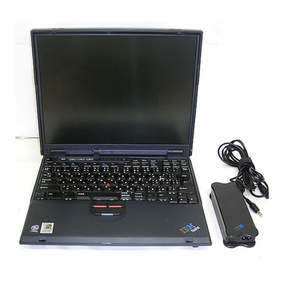
Locations Locations Front view System status indicators Battery and standby mode status indicators Built-in stereo speakers PC Card eject button PC Card slot Bay latch Eject button Ultrabay 2000 device Note: The Ultrabay 2000 accepts storage devices, such as a DVD drive, CD-ROM drive, CD-RW, ZIP250, 2nd HDD or 2nd battery. -
Page 92: Rear View
Locations Rear view Security keyhole Parallel connector Modem connector Network connector Serial connector External-monitor connector Universal serial bus (USB) connector External-input-device connector Power jack ThinkPad A21e... -
Page 93: Bottom View
Locations Bottom view Battery pack Battery pack latches Mini PCI card slot Docking connector DIMM slot Stereo headphone jack Stereo line-in jack Diskette drive Microphone jack Hard-disk drive LCD latches ThinkPad A21e... -
Page 94: Parts List
Parts list Parts list ThinkPad A21e... - Page 95 Mini PCI combo card (Intel)* 08K3125 Mini PCI combo card CR* 19K5888 Mini PCI combo card (3Com)* 22P6444 Mini PCI modem card (IBM CR)* 08K3338 Mini PCI modem card (Ambit)* 08K3252 Mini PCI Ethernet card (Intel)* 08K3348 for optional Mini PCI adapter, see “Optional FRUs” on...
- Page 96 Parts list Card modem connector (see “Miscellaneous parts” on page 96) Cover, Mini PCI adapter slot* 08K5673 Battery pack (6 cell), SANYO* 02K6618 Battery pack (6 cell), Panasonic* 02K6614 Battery pack (7 cell) NiMH, Panasonic* 02K6720 Battery pack (9 cell), SANYO* 02K6619 Battery pack (9 cell), Panasonic* 02K6615...
-
Page 97: Lcd Fru
Parts list LCD FRU 12.1-in. SVGA TFT LCD cover assembly 08K5655 for Korea 08K5659 LCD cable 27L0485 LCD panel (SANYO) 05K9577 Hinges 08K5664 Inverter card 08K3325 14.1-in. XGA TFT LCD cover assembly for MT2628-Ixx 08K5656 for MT2632 (i-series) 04P3724 LCD cable for MT2628-Ixx 27L0486 for MT2632 (i-series) -
Page 98: In. Xga Tft (Lg)
Parts list 15.0-in. XGA TFT (LG) LCD cover assembly 04P3048 for Korea 04P3049 LCD cable 27L0578 LCD panel (LG) 05K9647 Hinges 04P3488 Inverter card 08K3326 Misc kit (see “Miscellaneous parts” on page 96.) 04P3050 ThinkPad A21e... -
Page 99: Keyboard
Parts list Keyboard Language Arabic 02K5476 Belgian 02K5470 Canadian French 02K5456 Chinese, traditional 02K5459 Czech 02K5480 Danish 02K5467 Dutch 02K5464 European Spanish 02K5469 European French 02K5463 German 02K5462 Greek 02K5473 Hungarian 02K5479 Hebrew 02K5474 Italian 02K5468 Japanese 02K5458 Korean 02K5460 Latin American Spanish 02K5457 Norwegian... -
Page 100: Miscellaneous Parts
Parts list Miscellaneous parts Screw kit (including nylon-coated screws): 04P3973 v M2 x 3.6 mm, flat head (3) v M2 x 5.1 mm, flat head (5) v M2 x 5.7 mm, flat head (5) v M2 x 16 mm, bind head (3) v M2.5 x 4.8 mm, flat head (42) v M2.5 x 5.5 mm, flat head (2) v M2.5 x 15 mm, flat head (15) - Page 101 Parts list Miscellaneous parts, for diskette drive: 04P3967 v Bezel v Bracket v Flexible cable v Screw caps Miscellaneous parts, for LCD: 04P3968 v Latch (right/left) v Spring v Spacer (for 15.0-in.) v Blank cap, UltraPort v Screw caps Miscellaneous kit for LCD 15.0-in. LG 04P3050 v Latch (RH 15.0 LG) v Latch (LH 15.0 LG)
-
Page 102: Optional Frus
Mini PCI combo card (Intel) 08K3125 Mini PCI combo card CR 19K5888 Mini PCI combo card (3Com) 22P6444 Mini PCI modem card (IBM CR) 08K3338 Mini PCI modem card (Ambit) 08K3252 Mini PCI Ethernet card (Intel) 08K3348 Multiple battery charger... -
Page 103: Common Parts List
ThinkPad hardware maintenance diskette version – 1.61 Note: Download the file from the Web site. Power cords (system) IBM power cords for a specific country are usually available only in that region: For 2-pin power cords: Region Canada, United States of America... -
Page 104: Notices
Notices Notices References in this publication to IBM products, programs, or services do not imply that IBM intends to make these available in all countries in which IBM operates. Any reference to an IBM product, program, or service is not intended to state or imply that only that IBM product, program, or service may be used. - Page 105 Notices ThinkPad A21e...
- Page 106 Part Number: 06P8883 Printed in U.S.A. (1P) P/N: 06P8883...