
Related Manuals for Intel SR4850HW4 - Server Platform - 0 MB RAM


Summary of Contents for Intel SR4850HW4 - Server Platform - 0 MB RAM
- Page 1 ® Intel Server Platforms SR4850HW4 and SR4850HW4/M Product Guide Order Number: C92647-005 A guide for Technically Qualified Assemblers of Intel® Identified Subassemblies/Products.
- Page 2 Intel products including liability or warranties relating to fitness for a particular purpose, merchantability, or infringement of any patent, copyright or other intellectual property right. Intel products are not intended for use in medical, life saving, or life sustaining applications. Intel may make changes to specifications and product descriptions at any time, without notice.
-
Page 3: About This Manual
Hard drives PCI adapters Operating system For information about which of these items have been tested and can be used with your server platform, and for ordering information for Intel® products, see http://www.intel.com/support/motherboards/server/SR4850HW4/. Intel® Server Platforms SR4850HW4 & SR4850HW4/M Product Guide... -
Page 4: Additional Information And Software
Technical Product Specification about this product, including BIOS settings and chipset information If you just received this product Intel® Server Board SR4850HW4 and SR4850HW4/M Quick Start and need to install it User’s Guide in the product box For virtual system tours and A link to the SMaRT Tool is available under “Other Resources”... -
Page 5: Safety Information
EMC testing using a server board with a microprocessor from the same family (or higher) and operating at the same (or higher) speed as the microprocessor used on this server board. Intel® Server Platforms SR4850HW4 & SR4850HW4/M Product Guide... - Page 6 113 kg (250 lbs.). You must also consider the weight of any other device installed in the rack. A crush hazard exists should the rack tilt forward which could cause serious injury. Intel® Server Platforms SR4850HW4 & SR4850HW4/M Product Guide...
- Page 7 1470 W (5000 BTU/hr) for the server. The rack selected and the ventilation provided must be suitable to the environment in which the server is used. Intel® Server Platforms SR4850HW4 & SR4850HW4/M Product Guide...
-
Page 8: Safety Cautions
Safety Cautions Read all caution and safety statements in this document before performing any of the instructions. See also Intel® Server Boards and Server Chassis Safety Information on the Intel® Server Platforms SR4850HW4 and SR6850HW4 Deployment Toolkit CD and/or at http://www.intel.com/support/motherboards/server/sb/cs-010770.htm. - Page 9 Servers can be too heavy for a single person to lift or move safely. Depending on the server, use two people or a mechanical assist to lift or move the server. Intel® Server Platforms SR4850HW4 & SR4850HW4/M Product Guide...
-
Page 10: Wichtige Sicherheitshinweise
Wichtige Sicherheitshinweise Lesen Sie zunächst sämtliche Warnund Sicherheitshinweise in diesem Dokument, bevor Sie eine der Anweisungen ausführen. Beachten Sie hierzu auch die Sicherheitshinweise zu Intel Serverplatinen und Servergehäusen auf der Intel® Server Platforms SR4850HW4 and SR6850HW4 Deployment Toolkit oder unter http://www.intel.com/support/motherboards/server/sb/cs-... - Page 11 Stromanschluß des Produkts hauptsächlich über die Kabel unterbrochen wird. Um einen Server sicher anzuheben und zu bewegen ist eine Person nicht ausreichend. Bewegen Sie den Server, je nach Größe, entweder zu zweit oder mittels einer mecha- nischen Hilfe. Intel® Server Platforms SR4850HW4 & SR4850HW4/M Product Guide...
- Page 12 Preface 重要安全指导 在执行任何指令之前,请阅读本文档中的所有注意事项及安全声明。参见Intel® Server Platforms SR4850HW4 and SR6850HW4 Deployment Toolkit CD(资源光盘) 和/或 上的 Intel Server http://www.intel.com/support/motherboards/server/sb/cs-010770.htm Boards and Server Chassis Safety Information (《Intel 服务器主板与服务器机箱安全信息》)。 Intel® Server Platforms SR4850HW4 & SR4850HW4/M Product Guide...
- Page 13 Lisez attention toutes les consignes de sécurité et les mises en garde indiquées dans ce document avant de suivre toute instruction. Consultez Intel Server Boards and Server Chassis Safety Information sur le CD Intel® Server Platforms SR4850HW4 and SR6850HW4 Deployment Toolkit ou bien rendez-vous sur le site http://www.intel.com/support/motherboards/server/sb/cs-...
- Page 14 Il se peut que les serveurs soient trop lourds pour qu'une seule personne puisse les soulever et les déplacer en toute sécurité. En fonction du serveur, utilisez deux personnes ou utilisez un équipement mécanique auxiliaire pour soulever ou déplacer le serveur. Intel® Server Platforms SR4850HW4 & SR4850HW4/M Product Guide...
-
Page 15: Instrucciones De Seguridad Importantes
Instrucciones de seguridad importantes Lea todas las declaraciones de seguridad y precaución de este documento antes de realizar cualquiera de las instrucciones. Vea Intel Server Boards and Server Chassis Safety Information en el Intel® Server Platforms SR4850HW4 and SR6850HW4 Deployment Toolkit y/o en http://www.intel.com/support/motherboards/server/sb/cs-010770.htm. - Page 16 Los servidores pueden ser demasiado pesados para que una sola persona los levante o los mueva de forma segura. Dependiendo del servido, utilice dos personas o una ayuda mecánica para levantar o mover el servidor. Intel® Server Platforms SR4850HW4 & SR4850HW4/M Product Guide...
- Page 17 Se il sistema è stato a lungo in funzione, il microprocessore e il dissipatore di calore potrebbero essere surriscaldati. Fare attenzione alla presenza di piedini appuntiti e parti taglienti sulle schede e sul telaio. È consigliabile l'uso di guanti di protezione. Intel® Server Platforms SR4850HW4 & SR4850HW4/M Product Guide...
- Page 18 I server possono risultare troppo pesanti per essere sollevati o spostati da una sola persona. Alcuni server devono dunque essere sollevati o spostati da due persone o da un assistente tecnico. Intel® Server Platforms SR4850HW4 & SR4850HW4/M Product Guide...
-
Page 19: Table Of Contents
1 Platform Description ..................29 Platform Features........................30 Platform Front ........................31 Standard Control Panel ....................32 Intel ® Local Control Panel ................... 34 Platform Rear ........................36 Processors ..........................37 Plug-in Voltage Regulator Module (VRM) Converters..........37 System Memory ........................37 Available Memory Configurations................. - Page 20 Part II: Service Guide ..................135 5 User Serviceable Platform Components..........135 Tools and Supplies Needed ....................135 Equipment Log ......................135 Removing and Installing the Top Cover ................135 Removing the Top Cover ................... 136 Intel® Server Platforms SR4850HW4 & SR4850HW4/M Product Guide...
- Page 21 Installing the Center Brace ..................177 7 Servicing the Processors ................178 Handling the Intel® Xeon® Processors ................178 Processor VRM Requirements.................... 179 Installing and Removing a Processor Thermal Blank ............179 Intel® Server Platforms SR4850HW4 & SR4850HW4/M Product Guide...
- Page 22 Installing a Processor Core VRM Converter .............. 190 8 Servicing the RAID on Motherboard (ROMB) Components ....192 Installing and Removing the Intel® RAID Activation Key ............ 192 Installing the Intel® RAID Activation Key ..............192 Removing the Intel® RAID Activation Key ..............194 Installing and Removing the Intel®...
- Page 23 POST Error Pause Option..................256 Equipment Log ....................257 Regulatory Specifications and Disclaimers ..........259 Declaration of the Manufacturer or Importer .............. 259 Troubleshooting ....................262 Getting Help ..................... 263 Warranty......................265 Intel® Server Platforms SR4850HW4 & SR4850HW4/M Product Guide...
- Page 24 Figure 5. Rear Platform Features ....................36 Figure 6. Power Supply Indicators ..................... 41 Figure 7. Front View of Intel ® Server Platform SR4850HW4 and SR4850HW4/M ....43 Figure 8. Hard Disk Drive Carrier....................44 Figure 9. DVD/CD-ROM Drive Carrier ..................45 Figure 10.
- Page 25 Figure 93. Removing Thermal Blank ..................180 Figure 94. Installing Thermal Blank ..................181 Figure 95. Open Processor Socket Lever................183 Figure 96. Set Processor into Socket ..................184 Figure 97. Close Processor Socket Lever ................184 Intel® Server Platforms SR4850HW4 & SR4850HW4/M Product Guide...
- Page 26 Figure 104. Installing Processor 4 VRM .................. 191 Figure 105. Installing the Intel® RAID Activation Key.............. 193 Figure 106. Install Cable Inside the Intel® RAID Smart Battery ..........195 Figure 107. Route and Connect RAID Battery Cable .............. 196 Figure 108. Attach Intel® RAID Smart Battery to Chassis............196 Figure 109.
- Page 27 Table 23. POST Progress Codes and Messages............247 Table 24. BIOS Error Codes..................250 Table 25. Beep Codes....................255 Table 26. BIOS Recovery Beep Codes ............... 255 Table 27. Equipment Log .................... 257 Intel® Server Platforms SR4850HW4 & SR4850HW4/M Product Guide...
-
Page 28: Part I: User's Guide
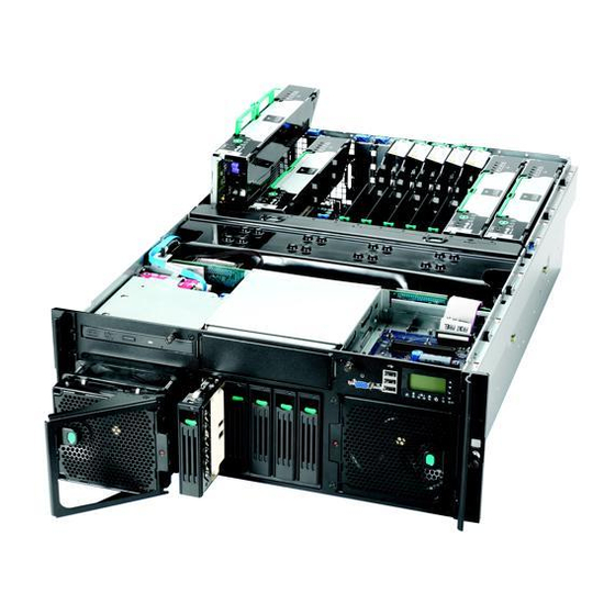
Part 1: User’s Guide describes the server platform and procedures that DO NOT REQUIRE a qualified service technician. ® Section 1 provides a brief overview of the Intel Server Platform SR4850HW4 and SR4850HW4/M, focusing on the chassis features. In this chapter, you will find a list of the server board/chassis features, photos of the product, and product diagrams to help you identify components and their locations. -
Page 29: Platform Description
® The Intel Server Platform SR4850HW4 and SR4850HW4/M is a compact, high-density, rack- ® ® mount system with support for one to four Intel Xeon processors and 64GB of DDR2 400MHz ® ® SDRAM memory. The system is based on the Intel Server Board Set SE8500HW4 and the Intel ®... -
Page 30: Platform Features
Four hot-swap system fans in a redundant (2+2) configuration Five hot-swap 1-inch Ultra320* SCSI hard disk drives Four Hot-plug memory boards (operating system support required) RAID on motherboard (ROMB) with a battery-backed DDR2 400MHz DIMM for disk cache Intel® Server Platforms SR4850HW4 & SR4850HW4/M Product Guide... -
Page 31: Platform Front
Description CD-ROM / DVD-ROM drive bay 5 ¼ peripheral bay Video connector USB 2.0 ports Front control panel. Standard control panel shown. Hot-swap fan modules Hot-swap disk drives Figure 2. Front Components Intel® Server Platforms SR4850HW4 & SR4850HW4/M Product Guide... -
Page 32: Standard Control Panel
Amber, Fast Hard drive rebuild Blinking (~2.5Hz) interrupted or rebuild on empty slot. LAN1, LAN2 Status LEDs Indicates LAN activity status. (green) State Description Idle Inactive No Access Blinking Active Access Intel® Server Platforms SR4850HW4 & SR4850HW4/M Product Guide... -
Page 33: Figure 3. Front Panel Controls And Indicators
System Power button Press to turn the system power on or off. System ID button Press to turn the System ID LED on or off. Figure 3. Front Panel Controls and Indicators Intel® Server Platforms SR4850HW4 & SR4850HW4/M Product Guide... -
Page 34: Intel ® Local Control Panel
Non-Critical Redundant power supply Alarm or blower failure. Non-critical blower, voltage, or temperature failure. J, K LAN1, LAN2 Status LEDs Indicates LAN activity status. (green) Idle Inactive No access Blinking Active Access Intel® Server Platforms SR4850HW4 & SR4850HW4/M Product Guide... -
Page 35: Figure 4. Intel ® Local Control Panel
Amber Fast Blinking Hard drive rebuild (~2.5 Hz) interrupted or rebuild on empty slot System Reset button Resets the system ® Figure 4. Intel Local Control Panel Intel® Server Platforms SR4850HW4 & SR4850HW4/M Product Guide... -
Page 36: Platform Rear
Amber On – 1000 Mbps H1, H2 AC input power connectors System ID button System ID LED (blue) DC jack (not used) Server Management RJ-45 connector (GCM) Figure 5. Rear Platform Features Intel® Server Platforms SR4850HW4 & SR4850HW4/M Product Guide... -
Page 37: Processors
MP with 1MB L2 Cache, 64-bit Intel Xeon ® ® processor MP with 8MB L3 Cache, or Dual-Core Intel Xeon processor 7000 sequence. These processors are targeted for multiprocessor servers. Several architectural and microarchitectural enhancements have been added to this processor, including an increased L2 cache size, an ®... -
Page 38: Available Memory Configurations
This configuration allows for hot-replacement of failing memory boards and hot-add and hot- replacement of memory DIMMs. Intel® Server Platforms SR4850HW4 & SR4850HW4/M Product Guide... - Page 39 NOTE Memory Hot-add must be supported by the operating system in order to perform this function. Check for any operating system restrictions. Intel® Server Platforms SR4850HW4 & SR4850HW4/M Product Guide...
-
Page 40: Power Subsystem
This feature allows the system to be powered by two separate AC sources. In the 1+1 configuration, the system continues to operate, without interruption, if one of the AC sources fails. Intel® Server Platforms SR4850HW4 & SR4850HW4/M Product Guide... -
Page 41: Figure 6. Power Supply Indicators
AC power source. Figure 6. Power Supply Indicators NOTE Proper system cooling requires that a power supply be installed in each power supply bay at all times. Intel® Server Platforms SR4850HW4 & SR4850HW4/M Product Guide... -
Page 42: Cooling Subsystem
Attention Indicator Amber Attention LED State Definition Normal: Normal operation Attention: Power fault or operational problem has occurred with this slot Blinking Locate: The slot is being identified at the user’s request. Intel® Server Platforms SR4850HW4 & SR4850HW4/M Product Guide... -
Page 43: Peripherals
One ½-inch IDE DVD-ROM/CD-ROM drive One 5 ¼-inch tape back-up device Item Description DVD-ROM / CD-ROM drive. SCSI DLT drive (optional). Hard drives (five). ® Figure 7. Front View of Intel Server Platform SR4850HW4 and SR4850HW4/M Intel® Server Platforms SR4850HW4 & SR4850HW4/M Product Guide... -
Page 44: Hot-Swap Scsi Hard Disk Drive Support
Amber flashing: Indicates hard drive is not powered on and has a fault condition. Unlit: Indicates no hard drive is installed in that location or a drive is installed, but no drive activity is taking place. Figure 8. Hard Disk Drive Carrier Intel® Server Platforms SR4850HW4 & SR4850HW4/M Product Guide... -
Page 45: Removable Media Drive Bay Support
The board set consists of the following boards: One main board One to four memory boards In addition, the server contains the following system boards: Front panel board SCSI backplane board Power distribution board SATA-to-IDE adapter board Intel® Server Platforms SR4850HW4 & SR4850HW4/M Product Guide... -
Page 46: Figure 10. Intel ® Server Platform Block Diagram
Platform Description Figure 10 displays a block diagram of the system, and the board set within the system. ® Figure 10. Intel Server Platform Block Diagram Intel® Server Platforms SR4850HW4 & SR4850HW4/M Product Guide... -
Page 47: Main Board
PCI-X* 133MHz – Hot-plug (Slot 2) Processor socket 3 PCI Express* x8 – Hot-plug (Slot 1) SCSI Connector channel A (internal) Ethernet LAN 1 (top), LAN 2 (bottom) VRM 9.1 Connector (processor cache) Intel® Server Platforms SR4850HW4 & SR4850HW4/M Product Guide... -
Page 48: Figure 11. Main Board Component Locations
Figure 11. Main Board Component Locations The main board supports the following: Up to four 64-bit Intel® Xeon® processor MP with 1MB L2 Cache, 64-bit Intel® Xeon® processor MP with 8MB L3 Cache, or Dual-Core Intel® Xeon® processor 7000 sequence. -
Page 49: Scsi Controller
There is also an option to install the Intel® RAID Smart Battery. With the Smart Battery, if power to the Intel® IOP332 Storage I/O Processor with Intel XScale® Microarchitecture drops below specifications, the Intel®... -
Page 50: Video Support
The Intel® Server Board SE8500HW4 Main Board has a standard DB15 video connector. Fibre Channel Module Support The Intel® Fibre Channel Module has a dedicated slot on the main board. The card is based on the Qlogic* ISP2322 FC-PCI-X controller. -
Page 51: Memory Board
PCI-Express* connectors. The Independent Memory Interface (IMI) bus connects the Intel® E8501 eXtended Memory Bridge on the memory board and the Intel® E8501 chipset North Bridge on the main board. The I C bus also goes through the memory connector linking the FRU device on the memory board to the server management (SM) bus on the main board. -
Page 52: Front Panel I/O Board
Figure 12. Hot-plug Memory Board LEDs and Buttons Front Panel I/O Board The Intel® Server Platform SR4850HW4 and SR4850HW4/M Front Panel I/O Board provides access to the system video and USB interfaces. It also interfaces to the Standard Control Panel or ®... -
Page 53: Power Distribution Board
NOTE Because hard disk drives have different cooling, power and vibration characteristics, Intel validates specific hard disk drive types in the Intel® Server Platform SR4850HW4 and SR4850HW4/M. See the Intel® Server Board SE8500HW4 Tested Hardware and Operating System List for a list of the supported drives. -
Page 54: Server Management
Platform Management Interruption (PMI) / System Diagnostic Interrupt (SDI) status monitor Event receiver System interface to the IPMB (via system interface ports) IPMI Management Controller Initialization Agent (MCIA) Emergency Management Port (EMP) interface Serial/modem and LAN alerting Intel® Server Platforms SR4850HW4 & SR4850HW4/M Product Guide... - Page 55 In this platform, the BMC is also the chassis bridge controller, providing integrated ICMB support. ICMB transports server management information between chassis in a cluster configuration that can contain multiple servers and peripherals. Intel® Server Platforms SR4850HW4 & SR4850HW4/M Product Guide...
-
Page 56: Starting Up And Shutting Down The Server
NOTE When installing a new Intel® Management Module remember to update the BMC with the correct server firmware. The firmware is updated after the server is powered on. Using incorrect BMC firmware may affect operation of the front control panel’s power button. -
Page 57: Shutting Down The Server
The +3.3V standby power is still available to the system even when it is not running. To remove standby power from the system, unplug all power cords from the system. Intel® Server Platforms SR4850HW4 & SR4850HW4/M Product Guide... -
Page 58: Intel® Server Deployment Toolkit
CD ROM burning software. Running Software Utilities from the CD The following procedure allows you to run the software utilities directly from the Intel® Server Platforms SR4850HW4 and SR6850HW4 Deployment Toolkit CD. 1. Insert the Intel® Server Platforms SR4850HW4 and SR6850HW4 Deployment Toolkit CD into the server’s CD-ROM drive. -
Page 59: Server Platform Utilities
4 Server Platform Utilities BIOS Setup Utility The BIOS Setup Utility is a text-based utility that allows you to configure the system and view and change device settings and view environmental information for the platform. The BIOS Setup Utility interface consists of several screens, called pages. Each page contains information or links to other pages. -
Page 60: Keyboard Commands
On 106-key Japanese keyboards, the plus key has a different scan code than the plus key on the other keyboard, but will have the same effect. This key only works for date and time. Intel® Server Platforms SR4850HW4 & SR4850HW4/M Product Guide... -
Page 61: Configuring Memory Options
9. Go back to the Memory menu option and enter a sparing threshold, between 1 and 15. 10. Select View and Configure Memory Board X option, where X is the memory board that is to be enabled as the spare. Intel® Server Platforms SR4850HW4 & SR4850HW4/M Product Guide... -
Page 62: Memory Raid
8. Press <F10> to save changes and exit. 9. Press “Y” at the prompt to save the changes. The server reboots to activate the changes. Intel® Server Platforms SR4850HW4 & SR4850HW4/M Product Guide... -
Page 63: System Configuration Reset
A second method to send a reset system configuration request to the server is to use the NVRAM_CLR jumper at location J4A4 on the main board. See letter “A” in Figure 15 to locate the jumper block and follow the instructions below the diagram. Intel® Server Platforms SR4850HW4 & SR4850HW4/M Product Guide... -
Page 64: Figure 15. Jumper Locations
Cover”. 12. Move the NVRAM Clear jumper at location JAA4 on the main board to cover pins 1 and 2. 13. Install the top cover. For instructions, see “Installing the Top Cover”. Intel® Server Platforms SR4850HW4 & SR4850HW4/M Product Guide... -
Page 65: Bios Upgrades And Recovery
NOTE A BIOS upgrade procedure can also be done with the latest available System ® Update Package (SUP) for the Intel Server Platform SR4850HW4 and SR4850HW4/M. This package is available at http://www.intel.com/support/motherboards/server/SR4850HW4/. Intel® Server Platforms SR4850HW4 & SR4850HW4/M Product Guide... -
Page 66: Table 6. Iflash32 Utility Command-Line Options And Parameters
This option is only supported in conjunction with the “/u” option. If an update is performed and this option is not specified, a message is displayed stating that you must perform a manual reset before the update will take effect. Intel® Server Platforms SR4850HW4 & SR4850HW4/M Product Guide... -
Page 67: Bios Recovery
Automatic recovery may be due to any of the following conditions: Flash integrity check failure: This includes corrupted header of the main BIOS or bad checksum. Incompatible versions of the recovery BIOS and the main BIOS. Intel® Server Platforms SR4850HW4 & SR4850HW4/M Product Guide... -
Page 68: Rolling Bios
The BIOS supports multiple consoles, some of which are in graphics mode and some in text mode. The graphics consoles can display the logo while the text consoles receive the redirected text. The console redirection ends at the beginning of the Legacy OS boot (INT 19h). Intel® Server Platforms SR4850HW4 & SR4850HW4/M Product Guide... -
Page 69: Keystroke Mappings
ExitBootServices. The operating system is responsible for continuing the Console Redirection after that point. BIOS console redirection is a text console and any graphical data such as a logo are not redirected. Intel® Server Platforms SR4850HW4 & SR4850HW4/M Product Guide... -
Page 70: Interface To Server Management
8. Leave the default settings for the other boxes. Click “Ok” to accept the settings and enter the Hyperterminal screen. 9. Power on the server. The console starts displaying the redirection once the video synchronizes on the server. Intel® Server Platforms SR4850HW4 & SR4850HW4/M Product Guide... -
Page 71: Lsi Logic* Mpt Scsi Utility
System Options Menu screen. The LSI Logic* MPT SCSI Utility main menu appears as shown in the figure below. Figure 16. LSI SCSI Utility Main Menu Press <F2> to select “Menu”. This provides access to the menu options “Boot Adapter List” and “Global Properties”. Intel® Server Platforms SR4850HW4 & SR4850HW4/M Product Guide... -
Page 72: Figure 17. Boot Adapter List
Service Technicians Guide The boot adapter list allows you to add or remove boot adapters. This screen is shown by the figure below. Figure 17. Boot Adapter List Intel® Server Platforms SR4850HW4 & SR4850HW4/M Product Guide... -
Page 73: Figure 18. Global Properties List
Scanning for devices. NOTE If the RAID on Motherboard (ROMB) feature is not enabled, the following message will be displayed: Current Firmware does not support IME RAID type. Press any key to continue. Intel® Server Platforms SR4850HW4 & SR4850HW4/M Product Guide... -
Page 74: Figure 19. Adapter Properties
CHS (Cylinder Head Sector) Mapping: “[SCSI Plug and Play Mapping]” or “[Alternate CHS Mapping]” Spin up delay (seconds): “[1]” to “[15]” Secondary Cluster Server: “[No]” or “[Yes]” Termination: “[Auto]” <Restore Defaults>: Allows you to restore the default configuration of the SCSI adapter. Intel® Server Platforms SR4850HW4 & SR4850HW4/M Product Guide... -
Page 75: Figure 20. Device Properties
Scan Luns >0: “[Yes]” or “[No]” Disconnect: “[On]” or “[Off]” SCSI Timeout: “[<10>]” Queue Tags: “[On]” or “[Off]” <Restore Defaults>: Discards all changes. No warning message is provided before discarding the changes. Intel® Server Platforms SR4850HW4 & SR4850HW4/M Product Guide... -
Page 76: Figure 21. Adapter And/Or Device Properties Exit Menu
“<Cancel Exit>”, “<Save Changes then exit this menu>”, and “<Discard changes then exit this menu>”. To exit the utility, select “<Exit the Configuration Utility>”. After exiting, the system will reboot. Figure 21. Adapter and/or Device Properties Exit Menu Intel® Server Platforms SR4850HW4 & SR4850HW4/M Product Guide... -
Page 77: Platform Confidence Test
Platform Confidence Test The Platform Confidence Test (PCT) diagnostic utility is included on the Intel® Server Platforms SR4850HW4 and SR6850HW4 Deployment Toolkit CD. The PCT checks the hardware configuration for incorrect assembly issues. Results are shown for field replaceable units (FRUs), such as the installed processor modules, the server board, disks, and memory. -
Page 78: Platform Confidence Test Options
The System Configuration Wizard (SCW) is a combination of software applications, batch files and helper applications that help you with the initial configuration of your Intel® server. The SCW supports IPMI 2.0, 1.5, and later compatible platforms. It performs the following activities: Set the system time and date in the BIOS. -
Page 79: Starting The System Configuration Wizard
The Intel® Server Management software will allow you to configure these items later, from the operating system. The SCW will ask you if you are using Intel® Server Management software and not prompt you to configure these items if you are using Intel® Server Management. -
Page 80: Using The Server Configuration Wizard Option
BIOS and the BMC. The SCW asks first if Intel® Server Management is installed on this server. If you select Yes, the SCW does not ask you about configuring LAN channel 1, the serial channel, or users. If you select No, you are given the option to configure these items through the SCW. -
Page 81: Figure 23. Configuration Options
Advanced Features of an Intel Management Module –Advanced ® Edition system configuration. This option is available only on a system that uses the Intel Management Module –Advanced Edition. ® If your server has the Intel Management Module –... -
Page 82: Configuring Sdrs And Frus
Each server comes with the FRUs pre-programmed, but you may want to refresh them from a current Intel® Server Platforms SR4850HW4 and SR6850HW4 Deployment Toolkit CD. The SCW supports loading ASCII FRU data from a file similar to the FRUSDR Load Utility’s MASTER.CFG file. -
Page 83: Configuring Channels
If your server has the Intel Management Module – Professional Edition, one LAN ® channel and one serial modem channel are supported. If your server has the Intel Management Module –Advanced Edition, your server supports one LAN channel, one serial modem channel, and one advanced LAN channel. -
Page 84: Figure 25. Lan Channel Setup Screen 1
The Subnet Mask IP address is entered as a dotted decimal IP address, such as 255.255.255.0. This option is available only if Static IP is selected. Intel® Server Platforms SR4850HW4 & SR4850HW4/M Product Guide... -
Page 85: Figure 26. Gateway Mac Address Resolution
IP address. Press this button if the resolution attempt failed because the server was not connected to the network. You will see the same dialog box when resolving the Backup Gateway MAC Address. Intel® Server Platforms SR4850HW4 & SR4850HW4/M Product Guide... -
Page 86: Figure 27. Lan Channel Setup Screen 2
If a channel privilege level is set at User level, for example, then users can only execute user-level commands, even if the user privilege level is set higher than User. The meanings of the different privilege level limits are explained below. Intel® Server Platforms SR4850HW4 & SR4850HW4/M Product Guide... - Page 87 255. SOL Baud Rate: The SOL Baud Rate dropdown list allows you to set SOL baud rate desired. The valid choices are 9600bps, 19.2kbps, 38.4kbps, 57.6kbps or 115.2kbps. Intel® Server Platforms SR4850HW4 & SR4850HW4/M Product Guide...
-
Page 88: Figure 28. Lan Channel Setup Screen 3
Alert Destination 1 MAC Address: The Alert Destination MAC Address is the physical or the Ethernet address of the Alert Destination. It corresponds to the Alert Destination IP Address. The MAC address is entered as six dotted hexadecimal bytes, such as 3e.4d.ab.12.c3.23. Intel® Server Platforms SR4850HW4 & SR4850HW4/M Product Guide... - Page 89 Address 1 radio button allows you to specify that all LAN alerts configured to go the first alert ® IP address are instead to be sent as emails. This option is available only on the Intel Management Module –Advanced Edition system configuration.
-
Page 90: Configuring The Serial/Modem Channel
Select All Button: This button will select all of the filter checkboxes on the dialog. Clear All: This button will clear all of the filter checkboxes on the dialog. Configuring the Serial/Modem Channel ® The Serial/Modem channel option is available on both the Intel Management Module – ® Professional Edition and Intel Management Module –Advanced Edition system configurations. -
Page 91: Figure 30. Modem Configuration
Modem Dial Command: The Modem Dial Command edit box allows you to enter the modem dial command string. This string is transmitted every time a Platform Event Page is sent. This string is sent before the paging string to indicate to the modem how to dial. Intel® Server Platforms SR4850HW4 & SR4850HW4/M Product Guide... -
Page 92: Figure 31. Remaining Serial/Modem Configuration Parameters
Serial/Modem connectivity. The valid choices are: Direct Connect: For applications that connect to the serial/modem port directly to another computer system. Modem Mode: For applications where the serial/modem port is connected to an external modem. Intel® Server Platforms SR4850HW4 & SR4850HW4/M Product Guide... -
Page 93: Figure 32. Configuring Serial Alerts
Paging String is determined at run time. The paging string is concatenated with the Alert Destination Phone Number entered on this screen. Therefore, it is not necessary to enter the Alert Destination Phone Number with the Paging String. Intel® Server Platforms SR4850HW4 & SR4850HW4/M Product Guide... -
Page 94: Figure 33. Configuring Serial Alert Filters
Figure 33. Configuring Serial Alert Filters “LAN Channel Configuration Screen 3 – LAN Alerting Setup” for information about this screen. Intel® Server Platforms SR4850HW4 & SR4850HW4/M Product Guide... -
Page 95: Select Users To Configure Screen
The Configure Users Screen provides a mechanism for configuring user access to LAN and ® Serial/Modem channels. A maximum of four users are supported by the Intel Server Platform SR4850HW4 and SR4850HW4/M. The screens allow configuration of user settings like username, password and the per-channel configuration for each user. -
Page 96: Configure Users Screen
LAN Channel 2 Privilege Level Limit: The LAN Channel 2 Privilege Level Limit dropdown list allows you to select the privilege level the user being configured. Intel® Server Platforms SR4850HW4 & SR4850HW4/M Product Guide... - Page 97 Management Module - Advanced Edition ® LAN Channel. This option is available only on the platform configuration that uses the Intel Management Module –Advanced Edition. Enable Telnet for this User: The Enable Telnet for this User checkbox is provided to Enable ®...
-
Page 98: Setting A System Asset Tag
FRUAREA, which is not known until the Asset Tag is saved to the server. It must have a minimum of two characters. The Continue button is disabled until a System Asset Tag has been entered. Figure 36. Setting the System Asset Tag Intel® Server Platforms SR4850HW4 & SR4850HW4/M Product Guide... -
Page 99: Configuring The Advanced Features
Advanced Features are configured through three main screens and several sub-screens. Each screen displays the configuration options for one or more of the advanced features. The Advanced ® Features are available only on the platform configuration that uses the Intel Management Module –Advanced Edition. - Page 100 IP to a remote client. In addition, keyboard and mouse activity from the remote console can ® be received for input to the managed server. This feature is available only on the Intel Management Module –Advanced Edition. Enable KVM: The KVM Enable checkbox, when checked, turns on the KVM feature for this server.
-
Page 101: Figure 38. Advanced Features Configuration Screen 2
1 – 65535. HTTP Host Name: The HTTP Host Name edit box allows the HTTP Host Name for this server to be set. The HTTP Host Name is the domain name of the system. Intel® Server Platforms SR4850HW4 & SR4850HW4/M Product Guide... -
Page 102: Figure 39. Advanced Features Configuration Screen 3
To Address: The To Address edit box is the email address of where the emails are being sent. Subject: The Mail Subject edit box is where the subject of the email can be entered. Intel® Server Platforms SR4850HW4 & SR4850HW4/M Product Guide... -
Page 103: Saving The Configuration To A Disk
If you check the option to save the server’s configuration, the SCW displays a file save dialog, allowing you to enter a location and file name where the configuration is to be saved. The file/open dialog follows the standard Windows file/open dialog scheme. Intel® Server Platforms SR4850HW4 & SR4850HW4/M Product Guide... -
Page 104: Saving The Configuration To The Server
If you selected Server Configuration Utilities from the Server Configuration Start Screen, shown below, you will be brought to an area of the utility from which you can run advanced server configuration utilities. Figure 41. System Configuration Wizard Start Screen Intel® Server Platforms SR4850HW4 & SR4850HW4/M Product Guide... -
Page 105: Figure 42. Selection Screen For Server Configuration Utilities
The choice of available utilities shown in this screen is only an example. Available utilities will vary by system configuration. The radio button options on the Utilities menu come from the MENU.CNF file on the Intel® Server Platforms SR4850HW4 and SR6850HW4 Server Deployment Toolkit CD. -
Page 106: Creating Diskettes
If you selected Create Diskettes from the Server Configuration Start Screen, shown below, you will be brought to an area of the utility from which you can driver and utility diskettes. Figure 43. System Configuration Wizard Start Screen Intel® Server Platforms SR4850HW4 & SR4850HW4/M Product Guide... -
Page 107: Creating Disk Sets By Operating System
SCW will switch to a DOS screen where you are prompted to insert the appropriate disk as the set is being created. After the diskette set has been created, you are returned to the “Create Operating System Diskettes” screen. Intel® Server Platforms SR4850HW4 & SR4850HW4/M Product Guide... -
Page 108: Device Driver Diskettes
Generically handle FRU devices that might not be associated with the BMC. Supply command lines and interactive input through the standard input device. View and direct results to the standard output device. Intel® Server Platforms SR4850HW4 & SR4850HW4/M Product Guide... -
Page 109: Running The Frusdr Load Utility
Upon completing the programming of the FRU and SDR areas, the server must be rebooted. Follow these steps to run the FRUSDR Load Utility from the Intel® Server Platforms SR4850HW4 and SR6850HW4 Deployment Toolkit CD: 1. Boot the Intel® Server Platforms SR4850HW4 and SR6850HW4 Deployment Toolkit CD. - Page 110 FRUSDR /? or /h Displays usage information. /d {smb,fru,sdr} Only displays requested area. /cfg filename.cfg Uses custom CFG file. Pause between blocks of data. Copyright (c) 1997-2004 Intel Corporation, All Rights Reserved Intel® Server Platforms SR4850HW4 & SR4850HW4/M Product Guide...
- Page 111 The Internal Use area is displayed in hex format, with 16 bytes per line. The board, chassis and product FRU areas end with an END OF FIELDS CODE, which indicates there is no more data in this area. Intel® Server Platforms SR4850HW4 & SR4850HW4/M Product Guide...
- Page 112 Manufacturer Name (ASCII) = Intel Product Name (ASCII) = MP Server Part Number (ASCII) = ..Product Version (ASCII) Serial Number (ASCII) = ..Asset Tag (ASCII) Mftr FRU File ID (ASCII) Intel® Server Platforms SR4850HW4 & SR4850HW4/M Product Guide...
- Page 113 FRUSDR Load Utility and to establish a configuration for the product. Some of the commands are user interactive and require you to input a choice when you run the FRUSDR Load Utility. Intel® Server Platforms SR4850HW4 & SR4850HW4/M Product Guide...
-
Page 114: Checking The Fru Data Integrity
FRU file with that which is programmed in the FRU non-volatile storage device. If specified, the Internal Use Area is then read from the specified FRU file and is programmed Intel® Server Platforms SR4850HW4 & SR4850HW4/M Product Guide... -
Page 115: Sel Viewer Utility
Sort the SEL records by various fields such as timestamp, sensor type number, event description, and generator ID. You can run this utility either directly from the Intel® Server Platforms SR4850HW4 and SR6850HW4 Deployment Toolkit CD or from a DOS device. To run the utility from a DOS device, copy the following files to a USB flash memory device or to a CD-ROM disk: SELView.exe... -
Page 116: Graphical User Interface
The SEL Viewer Utility main window supports the arrow keys, <PgDn>, <PgUp>, <Home>, and <End> to pan across the display window. It also supports the <F5> key to move forward to the next column and <F6> to move back to the previous column. Intel® Server Platforms SR4850HW4 & SR4850HW4/M Product Guide... -
Page 117: Figure 45. Sel Viewer Utility Main Window
The main window is shown in the following diagram. Figure 45. SEL Viewer Utility Main Window Intel® Server Platforms SR4850HW4 & SR4850HW4/M Product Guide... -
Page 118: Figure 46. Sel Records In Hex Format
Event Dir and Event Type Event Data 1 Event Data 2 Event Data 3 Manufacturers ID (used when displaying OEM SEL records type C0h-DFh) OEM defined (used when displaying OEM SEL records type C0h-DFh and E0h-FFh) Intel® Server Platforms SR4850HW4 & SR4850HW4/M Product Guide... -
Page 119: Figure 47. File Open Window
The interpreted text format files contain the SEL properties in the first lines followed by a blank line and the column headings. The SEL file format is specified as an ASCII-readable Intel® Server Platforms SR4850HW4 & SR4850HW4/M Product Guide... -
Page 120: Figure 48. Sel Properties
Figure 49. Confirmation for Clearing SEL Sort By: Under the SEL pull-down menu, use Sort By to sort the SEL data fields. This option provides a list of fields by which the entries can be sorted. Intel® Server Platforms SR4850HW4 & SR4850HW4/M Product Guide... -
Page 121: Figure 50. General Help Window
Use the arrow keys to select between topics and use the <F10> or <Tab> keys to move between panes. To dismiss the help window, press <Esc> key. See the figure below for the General Help screen. Figure 50. General Help Window Intel® Server Platforms SR4850HW4 & SR4850HW4/M Product Guide... -
Page 122: Fru Viewer Utility
.STR file is a Unicode file, it allows internationalization of the FRU Viewer Utility. You can run this utility either directly from the Intel® Server Platforms SR4850HW4 and SR6850HW4 Deployment Toolkit CD or from a DOS device. To run the utility from a DOS device, copy the following files to a USB flash memory device or to a CD-ROM disk: FRUView.exe... -
Page 123: Using The Fru Viewer Utility
Using the FRU Viewer Utility Follow these steps to use the FRU Viewer Utility: 1. Boot to the Intel® Server Platforms SR4850HW4 and SR6850HW4 Deployment Toolkit CD. 2. Exit the SCW. 3. Type CD FRUVIEW to change to the FRU Viewer folder. -
Page 124: Figure 52. Fru Viewer Utility Main Window
<F6> to move back to the previous column. Use the <Tab> key to move to the next window in the client area or to move to the menu. Use <F10> key to move between the client area and the menu. Intel® Server Platforms SR4850HW4 & SR4850HW4/M Product Guide... -
Page 125: Figure 53. File Open Dialog Box
<Home>, <End>, Left/Right arrows and <Ins>. The <Ins> key toggles insert and overwrite editing while in the edit box and this is noted with “INS” or “OVR”, displayed in the lower-right corner of the dialog box. Figure 53. File Open Dialog Box Intel® Server Platforms SR4850HW4 & SR4850HW4/M Product Guide... -
Page 126: Figure 54. Fru Menu
FRU. By default the first FRU entry is shown in the display pane when the FRU Viewer Utility is started. Figure 54. FRU Menu Intel® Server Platforms SR4850HW4 & SR4850HW4/M Product Guide... -
Page 127: Figure 55. Fru Properties
FRU data is read again from the server and displayed. When High resolution mode is selected, the utility displays FRU data as shown in Figure 56 . Figure 56. High Resolution Mode Intel® Server Platforms SR4850HW4 & SR4850HW4/M Product Guide... -
Page 128: Figure 57. Help Window
About: From the Help pull-down menu, use the About option to display the version of the FRU Viewer Utility, the IPMI version, and copyright information. See the figure below. Figure 58. About Window Intel® Server Platforms SR4850HW4 & SR4850HW4/M Product Guide... -
Page 129: Save And Restore System Configuration (Syscfg)
BMC release 11. Write down the name of the HEX file. You will need it later. Firmwareupdate.txt <name>.txt 2. Boot to DOS. Intel® Server Platforms SR4850HW4 & SR4850HW4/M Product Guide... - Page 130 /u /op /p name.hex NOTES A jumper at location J1B1 on the Intel® Management Module must cover pins 1 and 2 to update the boot block. Cover pins 2 and 3 on this jumper to write-protect the BMC boot block.
-
Page 131: Firmware Update Utility Command-Line Options
Restarts the boot code by exiting fw transfer mode and re-entering fw transfer mode after programming the boot code. /noexit The utility will not exit fw transfer mode after entering it, except when the restartboot option is specified. Intel® Server Platforms SR4850HW4 & SR4850HW4/M Product Guide... -
Page 132: Table 9. Fwpiaupd Command-Line Arguments For Direct Hsc Update
Overrides platform checking by disabling the compare of the current flash images device info block with that contained in the hex file. /noexit The utility will not exit fw transfer mode after entering it. Intel® Server Platforms SR4850HW4 & SR4850HW4/M Product Guide... -
Page 133: Extensible Firmware Interface (Efi) Shell
Displays device tree dh [-b] [-p prot_id] | [handle] Dumps handle information disconnect DeviceHandle# Disconnects device from driver [DriverHandle# [ChildHandle#] dmem {address] [size] [;MMIO] Displays the contents of memory dmpstore Dumps the variable store Intel® Server Platforms SR4850HW4 & SR4850HW4/M Product Guide... - Page 134 Delays for the specified number of microseconds time [hh:mm:ss] Gets or sets the time type [-a] [-u] [-b] file Displays the contents of a file Displays version information vol fs [volume_label] Sets or displays a volume label Intel® Server Platforms SR4850HW4 & SR4850HW4/M Product Guide...
-
Page 135: Part Ii: Service Guide
With the exception of the components described in this chapter, all servicing must be done by a qualified service technician. Intel® Server Platforms SR4850HW4 & SR4850HW4/M Product Guide... -
Page 136: Removing The Top Cover
4. Slide the top cover toward the back of the chassis until the tabs on the cover disengage with the slots in the chassis. 5. Lift the cover to remove it. TP01403 Figure 59. Removing the Top Cover Intel® Server Platforms SR4850HW4 & SR4850HW4/M Product Guide... -
Page 137: Installing The Top Cover
3. Slide the top cover towards the front of the chassis until it is fully closed. 4. Tighten the captive screws on the faceplate of the chassis. 5. Slide the server into the rack. TP01404 Figure 60. Installing the Top Cover Intel® Server Platforms SR4850HW4 & SR4850HW4/M Product Guide... -
Page 138: Hot-Swapping A System Fan Assembly
3. Press the green button on the front of the fan assembly to release the handle. See letter “B” in the figure. 4. Use the handle to pull the fan from the system. See letter “C” in the figure. TP01445 Figure 61. System Fan Location and Removal Intel® Server Platforms SR4850HW4 & SR4850HW4/M Product Guide... -
Page 139: Hot-Swapping Hard Disk Drives
CAUTION To ensure proper airflow and server cooling, all drive bays must contain either a carrier with a hard drive installed in it or a carrier with an air baffle installed. Intel® Server Platforms SR4850HW4 & SR4850HW4/M Product Guide... -
Page 140: Determining Drive Status
Amber flashing: Indicates hard drive is not powered on and has a fault condition. Unlit: Indicates no hard drive is installed in that location, or a drive is installed but has no current activity. Figure 63. Hard Disk Drive Carrier Intel® Server Platforms SR4850HW4 & SR4850HW4/M Product Guide... -
Page 141: Removing A Hard Disk Drive
7. Remove the air baffle from the carrier. See letter “B” in the figure. 8. Store the air baffle for future reinstallation. TP01432 Figure 65. Removing the Air Baffle from the Hard Disk Drive Carrier Intel® Server Platforms SR4850HW4 & SR4850HW4/M Product Guide... -
Page 142: Installing A Hard Disk Drive Assembly
3. Use the handle to push the carrier until it docks in the chassis, then close the drive carrier handle. See letter “B” in the figure. TP01434 Figure 67. Installing Hard Disk Drive into Server Intel® Server Platforms SR4850HW4 & SR4850HW4/M Product Guide... -
Page 143: Hot-Swapping Power Supplies
5. Pull the power supply from the chassis and set it on a clean, ESD-protected work surface. See letter “C” in the figure. 6. Install a replacement power supply or a filler panel. For instructions, see “Installing a Power Supply”. TP01451 Figure 68. Removing a Power Supply Intel® Server Platforms SR4850HW4 & SR4850HW4/M Product Guide... -
Page 144: Installing A Power Supply
Figure 69. Installing a Power Supply 9. Plug the power cord into the AC receptacle on the power supply. 10. Use the LEDs on the power supply to confirm the power supply is functioning. Intel® Server Platforms SR4850HW4 & SR4850HW4/M Product Guide... -
Page 145: Installing And Removing Pci Cards
4. Select the device to be removed and click “Stop”. 5. Wait for the PCI slot power LED at the rear if the slot to turn off. 6. Disconnect any cables attached to the card. Intel® Server Platforms SR4850HW4 & SR4850HW4/M Product Guide... -
Page 146: Figure 70. Removing A Pci Card
See letter “C” in Figure 70. To install a replacement PCI card: see “Installing a Hot-plug PCI Add-in Card”. 12. Install the top cover. For instructions, see “Installing the Top Cover”. Intel® Server Platforms SR4850HW4 & SR4850HW4/M Product Guide... -
Page 147: Removing Hot-Plug Pci Card With Hardware Hot-Plug Interface
See letter “C” in Figure 70. To install a replacement PCI card: see “Installing a Hot-plug PCI Add-in Card”. 11. Install the top cover. For instructions, see “Installing the Top Cover”. Intel® Server Platforms SR4850HW4 & SR4850HW4/M Product Guide... -
Page 148: Installing A Hot-Plug Pci Add-In Card
“D” in the figure. 9. Press the card down firmly until it seats into the slot. TP01429 Figure 72. Installing a Hot-plug PCI Add-in Card Intel® Server Platforms SR4850HW4 & SR4850HW4/M Product Guide... -
Page 149: Removing A Non-Hot-Plug Pci Card
3. Power down the system and unplug both AC power cords to remove power from the server. 4. Remove the top cover. For instructions, see “Removing the Top Cover”. 5. Disconnect any cables attached to the PCI card. Intel® Server Platforms SR4850HW4 & SR4850HW4/M Product Guide... -
Page 150: Installing A Non-Hot-Plug Pci Card
11. Rotate the retention latch at the rear of the card slot into the down position. 12. Attach the required cables to the PCI card. 13. Install the top cover. For instructions, see “Installing the Top Cover”. Intel® Server Platforms SR4850HW4 & SR4850HW4/M Product Guide... -
Page 151: Installing And Removing The Fibre Channel Module
11. Install the memory board or memory board air baffle into Slot C. For instructions, see “Cold Insertion of a Memory Board”. 12. Install the top cover. For instructions, see “Installing the Top Cover”. Intel® Server Platforms SR4850HW4 & SR4850HW4/M Product Guide... -
Page 152: Installing The Fibre Channel Module
13. Install the memory board or memory board air baffle into Slot C. For instructions, see “Cold Insertion of a Memory Board”. 14. Install the top cover. For instructions, see “Installing the Top Cover”. Intel® Server Platforms SR4850HW4 & SR4850HW4/M Product Guide... -
Page 153: Installing And Removing Memory Boards
Maximum Compatibility, Memory RAID, or Memory Mirroring, you must power down your server before removing or installing any memory board or memory DIMMs. For instructions, see “Cold Removal of Memory Board” “Cold Insertion of a Memory Board”. Intel® Server Platforms SR4850HW4 & SR4850HW4/M Product Guide... -
Page 154: Removing Memory Board Air Baffle
4. Push the tab between the two holes in the direction of the arrow. See letter “A” in Figure 74. 5. Lift the memory board air baffle from the server. See letter “B” in the figure. TP01416 Figure 74. Removing Memory Board Air Baffle Intel® Server Platforms SR4850HW4 & SR4850HW4/M Product Guide... -
Page 155: Installing Memory Board Air Baffle
1. Observe the safety precautions, warnings, and cautions described in “Safety Information”. 2. Remove the top cover. For instructions, see “Removing the Top Cover”. Intel® Server Platforms SR4850HW4 & SR4850HW4/M Product Guide... -
Page 156: Figure 76. Memory Module Buttons And Leds
If the attention LEDs do not turn off, your configuration may not support Hot-plug memory board activity. For instructions on non-Hot-plug memory board maintenance, see “Cold Removal of Memory Board” and “Cold Insertion of a Memory Board”. Intel® Server Platforms SR4850HW4 & SR4850HW4/M Product Guide... -
Page 157: Figure 77. Memory Board Removal
By pulling the handle, power to the slot will be immediately disabled. The “surprise hot-remove” action may cause the operating system to crash, but will not electrically damage the system. Intel® Server Platforms SR4850HW4 & SR4850HW4/M Product Guide... -
Page 158: Hot-Insertion Of A Memory Board
4. Push the handle down into the fully-locked position. See letter “B” in the figure. 5. Install the top cover. For instructions, see “Installing the Top Cover”. TP01454 Figure 78. Installing Memory Board Intel® Server Platforms SR4850HW4 & SR4850HW4/M Product Guide... -
Page 159: Cold Removal Of Memory Board
“A” in Figure 78. 9. Push the handle down into the fully-locked position. See letter “B” in Figure 78. 10. Install the top cover. For instructions, see “Installing the Top Cover”. Intel® Server Platforms SR4850HW4 & SR4850HW4/M Product Guide... -
Page 160: Installing And Removing Dimms
Use only DDR2 DIMMs. Other DIMMs will not fit into the socket. Attempts to force a non- DDR2 DIMM into a socket will damage either the socket or the DIMM. Figure 79. Use Only DDR2 DIMMs Intel® Server Platforms SR4850HW4 & SR4850HW4/M Product Guide... -
Page 161: Installing Dimms
Press on the tab labeled “C” in the figure. Lift the memory board DIMM cover from the memory board. See letter “D” in the figure. TP01439 Figure 80. Remove Memory Board DIMM Cover Intel® Server Platforms SR4850HW4 & SR4850HW4/M Product Guide... -
Page 162: Figure 81. Install Dimms
9. Push down on the top edge of the DIMM. The levers at each end of the DIMM socket will close. Make sure the levers close securely. See letter “D” in the figure. DIMM 1B DIMM 1A DIMM 2B DIMM 2A TP01440 Figure 81. Install DIMMs Intel® Server Platforms SR4850HW4 & SR4850HW4/M Product Guide... -
Page 163: Figure 82. Install Memory Board Dimm Cover
Figure 82. Install Memory Board DIMM cover 11. Install the memory board. For instructions, see “Hot-insertion of a Memory Board” or “Cold Insertion of a Memory Board”, depending on your server configuration. Intel® Server Platforms SR4850HW4 & SR4850HW4/M Product Guide... -
Page 164: Removing Dimms
8. Install the memory board or install a memory board air baffle into the memory board slot. For instructions, see “Hot-insertion of a Memory Board” or “Cold Insertion of a Memory Board”, depending on your server configuration. Intel® Server Platforms SR4850HW4 & SR4850HW4/M Product Guide... -
Page 165: Technician's Serviceable Platform Components
6 Technician’s Serviceable Platform Components This chapter presents procedures that describe removal and installation of many components inside the system. Tools and Supplies Needed Procedures in this part require the following tools and supplies: Jumper-removal tool or needle-nosed pliers Phillips* #2 screwdriver Torx screwdrivers (T-15) Antistatic wrist strap and conductive foam pad (recommended) As you integrate new parts into the system, add information about them to the... -
Page 166: Safety: Before Top Cover Removal
0.90 N-m (8 in-lb) Hard Drive Carrier 0.90 N-m (8 in-lb) Component Locations Use the following figures to help you locate components you may need to remove or disconnect to service components. Intel® Server Platforms SR4850HW4 & SR4850HW4/M Product Guide... -
Page 167: Figure 83. Main Board Component Locations
On board RAID Cache Memory (DDR-2) Real-time clock battery connector SATA connector Memory board D Front Panel connector Fibre Channel Module connector Intel® Management Module (IMM) Memory board C Figure 83. Main Board Component Locations Intel® Server Platforms SR4850HW4 & SR4850HW4/M Product Guide... -
Page 168: Figure 84. Scsi Backplane Board Component Locations
SCSI cable connector side of board (five) Figure 84. SCSI Backplane Board Component Locations TP01449 Item Description Control Panel connector Main board connector SCSI backplane board connector Figure 85. Front Panel Board Component Locations Intel® Server Platforms SR4850HW4 & SR4850HW4/M Product Guide... -
Page 169: Removing And Installing The Top Cover
4. Slide the top cover toward the back of the chassis until the tabs on the cover disengage with the slots in the chassis. See letter “B” in the figure. 5. Lift the cover from the chassis. TP01403 Figure 86. Removing the Top Cover Intel® Server Platforms SR4850HW4 & SR4850HW4/M Product Guide... -
Page 170: Installing The Top Cover
3. Slide the top cover towards the front of the chassis until it is fully closed. See letter “A” in Figure 87. 4. Tighten the captive screws on the faceplate of the chassis. See letter “B” in the figure. TP01404 Figure 87. Installing the Top Cover Intel® Server Platforms SR4850HW4 & SR4850HW4/M Product Guide... -
Page 171: Removing And Installing The Processor Air Baffle
8. Disconnect the CD-ROM/DVD/ROM power cable from the SCSI backplane board. See letter “D” in Figure 84 to locate the cable connection point. 9. Disconnect any cables attached to the device in the 5 ¼” peripheral bays. Intel® Server Platforms SR4850HW4 & SR4850HW4/M Product Guide... -
Page 172: Figure 88. Removing The Processor Air Baffle
11. Pull the baffle up and back to disengage the baffle from the two-sheetmetal tabs at the front of the baffle. 12. Lift the baffle up to remove it. See letter “B” in the figure. TP01413 Figure 88. Removing the Processor Air Baffle Intel® Server Platforms SR4850HW4 & SR4850HW4/M Product Guide... -
Page 173: Installing The Processor Air Baffle
1. Insert the front processor air baffle under the two metal tabs at the front of the baffle, just below the SCSI backplane board. One tab is located on each side of the chassis. See letter “A” in Figure 89. TP01415 Figure 89. Installing the Processor Air Baffle Intel® Server Platforms SR4850HW4 & SR4850HW4/M Product Guide... -
Page 174: Figure 90. Engaging The Processor Air Baffle Guides
6. Connect the CD-ROM/DVD ROM power cable to the SCSI backplane board. See letter “D” in Figure 84 to locate the cable connection point. 7. Connect any cables attached to the device in the 5 ¼” peripheral bay. Intel® Server Platforms SR4850HW4 & SR4850HW4/M Product Guide... -
Page 175: Removing And Installing The Center Brace
5. Slide the latches at each side of the chassis to the unlock position. See letter “A” in Figure 91. 6. Lift the center brace from the chassis. See letter “B” in the figure. Intel® Server Platforms SR4850HW4 & SR4850HW4/M Product Guide... -
Page 176: Figure 91. Removing The Center Brace
Working Inside the System TP01414 Figure 91. Removing the Center Brace Intel® Server Platforms SR4850HW4 & SR4850HW4/M Product Guide... -
Page 177: Installing The Center Brace
1. Set the center brace into position in the chassis. See Figure 92. 2. Slide the latches at each side of the chassis to the locked position. TP01457 Figure 92. Installing the Center Brace Intel® Server Platforms SR4850HW4 & SR4850HW4/M Product Guide... -
Page 178: Servicing The Processors
The Intel Server Platform SR4850HW4 requires a minimum of one 64-bit Intel® Xeon® processor MP with 1MB L2 Cache or 64-bit Intel® Xeon® processor MP with 8MB L3 Cache. The following rules must be followed: Each processor socket must include either a processor thermal blank, or a processor and heat sink combination. -
Page 179: Processor Vrm Requirements
The VRMs necessary depend on the number of processors and the main board model installed. Before installing or removing any processors, consult the board specific Technical Product Specification at http://www.intel.com for specific VRM requirements. As an overview the following generic VRM rules apply:... -
Page 180: Figure 93. Removing Thermal Blank
8. Install a processor in the empty socket. For instructions, see “Installing a Processor”. 9. Install the processor air baffle. For instructions, see “Installing the Processor Air Baffle”. 10. Install the top cover. For instructions, see “Installing the Top Cover”. Intel® Server Platforms SR4850HW4 & SR4850HW4/M Product Guide... -
Page 181: Installing A Processor Thermal Blank
TP01428 Figure 94. Installing Thermal Blank 9. Install the processor air baffle. For instructions, see “Installing the Processor Air Baffle”. 10. Install the top cover. For instructions, see “Installing the Top Cover”. Intel® Server Platforms SR4850HW4 & SR4850HW4/M Product Guide... -
Page 182: Installing And Removing A Processor
“Installing the Processor Air Baffle”. 13. Install the top cover. For instructions, see “Installing the Top Cover”. NOTE Once the processor is removed, note that the release mechanism shows the socket is open. Intel® Server Platforms SR4850HW4 & SR4850HW4/M Product Guide... -
Page 183: Installing A Processor
6. If a Processor Thermal Blank is installed, remove it. For instructions, see “Removing a Processor Thermal Blank”. 7. Verify that the processor release mechanism is in the open position. See Figure 95. TP01424 Figure 95. Open Processor Socket Lever Intel® Server Platforms SR4850HW4 & SR4850HW4/M Product Guide... -
Page 184: Figure 96. Set Processor Into Socket
9. Once the processor is in the socket, gently press the processor to verify the processor has seated properly. TP01425 Figure 96. Set Processor into Socket 10. Close the processor release lever. See Figure 97. TP01426 Figure 97. Close Processor Socket Lever Intel® Server Platforms SR4850HW4 & SR4850HW4/M Product Guide... -
Page 185: Installing Or Removing Processor Vrm Converters
3. Power down the system and unplug both AC power cords. 4. Remove the top cover. For instructions, see “Removing the Top Cover”. 5. Remove the processor air baffle. For instructions, see “Removing the Processor Air Baffle”. Intel® Server Platforms SR4850HW4 & SR4850HW4/M Product Guide... -
Page 186: Figure 98. Removing A Processor Cache Vrm Converter
9. Install the processor air baffle. For instructions, see “Installing the Processor Air Baffle”. 10. Install the top cover. For instructions, see “Installing the Top Cover”. TP01459 Figure 98. Removing a Processor Cache VRM Converter Intel® Server Platforms SR4850HW4 & SR4850HW4/M Product Guide... -
Page 187: Installing The Processor Cache Vrm Converter
9. Install the processor air baffle. For instructions, see “Installing the Processor Air Baffle”. 10. Install the top cover. For instructions, see “Installing the Top Cover”. TP01536 Figure 99. Installing a Processor Cache VRM Converter Intel® Server Platforms SR4850HW4 & SR4850HW4/M Product Guide... -
Page 188: Removing The Processor Core Vrm Converters
Push down at the top of the baffle to unlatch it. See letter “A” in Figure 100. Pull the cover out at an angle. See letter “B” in the figure. TP01539 Figure 100. Removing Processor 4 Core VRM Baffle Intel® Server Platforms SR4850HW4 & SR4850HW4/M Product Guide... -
Page 189: Figure 101. Removing Processor 3 Core Vrm
3 VRM, see letter “B” and “C” in Figure 101. If you are removing the processor 4 VRM, see letter “B” and “C” in Figure 102. TP01460 Figure 101. Removing Processor 3 Core VRM TP01461 Figure 102. Removing Processor 4 Core VRM Converter Intel® Server Platforms SR4850HW4 & SR4850HW4/M Product Guide... -
Page 190: Installing A Processor Core Vrm Converter
Do not exert excessive force. Notches in the VRM converter’s connector and corresponding barriers on the main board’s sockets prevent incorrect insertion. Forcing the wrong VRM converter into a connector can damage the VRM converter or the connector. Intel® Server Platforms SR4850HW4 & SR4850HW4/M Product Guide... -
Page 191: Figure 103. Installing Processor 3 Vrm
“Cold Insertion of a Memory Board”. 13. Install the top cover. For instructions, see “Installing the Top Cover”. TP01421 Figure 103. Installing Processor 3 VRM TP01422 Figure 104. Installing Processor 4 VRM Intel® Server Platforms SR4850HW4 & SR4850HW4/M Product Guide... -
Page 192: Servicing The Raid On Motherboard (Romb) Components
5. Remove the memory board air baffle or the memory board from Slot C. For instructions, see “Cold Removal of Memory Board”. 6. If a PCI card is in Slot 7, remove it to expose the Intel® RAID Activation Key holder. For instructions on removing a PCI card, see “Removing a Non-Hot-Plug PCI Card”. - Page 193 RAID DIMM, see “Installing the RAID DDR2-400 DIMM”. TP01418 Figure 105. Installing the Intel® RAID Activation Key 9. Install the memory board air baffle or the memory board into Slot C. For instructions, see “Cold Insertion of a Memory Board”.
-
Page 194: Removing The Intel® Raid Activation Key
5. Remove the memory board air baffle or the memory board from Slot C. For instructions, see “Cold Removal of Memory Board”. 6. If a PCI card is in Slot 7, remove it to expose the Intel® RAID Activation Key holder. For instructions on removing a PCI card, see “Removing a Non-Hot-Plug PCI Card”. -
Page 195: Installing And Removing The Intel® Raid Smart Battery
Support for a DDR2 DIMM serves as memory for the Intel® IOP332 Storage I/O Processor, and as a disk cache to store write data to the drives. If power to the Intel® IOP332 Storage I/O Processor with Intel XScale® Microarchitecture drops below specifications, a battery back-up unit maintains the contents of the DIMM by keeping the DIMM in self-refresh mode until power is restored. -
Page 196: Figure 107. Route And Connect Raid Battery Cable
Figure 107. Route and Connect RAID Battery Cable 9. Fit the hooks on the back of the battery into the matching slots on the chassis. See Figure 108. TP01407 Figure 108. Attach Intel® RAID Smart Battery to Chassis Intel® Server Platforms SR4850HW4 & SR4850HW4/M Product Guide... -
Page 197: Removing The Intel® Raid Smart Battery
7. Pinch the top and bottom covers of the battery holder to open it. 8. Remove the Intel® RAID Smart Battery from the chassis. 9. Install the memory board or the Memory Baffle air baffle into Slot D. For instructions, see “Cold Insertion of a Memory... -
Page 198: Installing And Removing The Raid Ddr2-400 Dimm
Make sure the clips are firmly in place. See Figure 110. NOTE Letter “C” in Figure 110 shows the installation of the RAID Activation Key. The Intel® RAID Activation Key is also required to activate ROMB. For instructions on installing the Intel® RAID Activation Key, see “Installing the Intel®... -
Page 199: Removing The Raid Ddr2 Dimm
9. Install the memory board or the memory board air baffle into Slot C. For instructions, see “Cold Insertion of a Memory Board”. 10. Install the top cover. For instructions, see “Installing the Top Cover”. Intel® Server Platforms SR4850HW4 & SR4850HW4/M Product Guide... -
Page 200: Servicing The Peripheral Area Components
9 Servicing the Peripheral Area Components Installing the External SCSI Cable Assembly The optional external SCSI cable assembly allows external SCSI components to be connected to the chassis. To install the external SCSI cable assembly: 1. Observe the safety precautions, warnings, and cautions described in “Safety Information”. -
Page 201: Replacing Removable Media Devices
Cover”. Replacing Removable Media Devices The Intel® Server Platform SR4850HW4 and SR4850HW4/M can accommodate a DVD/CD-ROM device and one 5 ¼” peripheral device. The devices are not hot-swappable, so the system must be powered down and the power cords removed from the chassis before the devices can be serviced. -
Page 202: Figure 113. Removing The Cd-Rom/Dvd-Rom Drive From The Carrier
10. Store the drive in an antistatic protective wrapper or in its original packaging. 11. Install a new CD-ROM / DVD-ROM drive into the carrier or slide the empty carrier into the server. 12. Install the top cover. For instructions, see “Installing the Top Cover”. Intel® Server Platforms SR4850HW4 & SR4850HW4/M Product Guide... -
Page 203: Installing The Cd-Rom/Dvd-Rom Drive
8. Place the left side of the drive into the drive carrier as shown in Figure 114. 9. Press the CD-ROM/DVD-ROM drive into the carrier until it is firmly secured. TP01470 Figure 114. Assembling the CD-ROM/DVD-ROM Drive and Carrier Intel® Server Platforms SR4850HW4 & SR4850HW4/M Product Guide... -
Page 204: Figure 115. Inserting The Cd-Rom/Dvd-Rom Drive Carrier Into The Platform
11. Plug the SATA cable and power cable into the converter board. See letter “B” in the figure. 12. Install the top cover. For instructions, see “Installing the Top Cover”. TP01471 Figure 115. Inserting the CD-ROM/DVD-ROM Drive Carrier into the Platform Intel® Server Platforms SR4850HW4 & SR4850HW4/M Product Guide... - Page 205 5. Push the tabs at each side of the carrier filler panel. See letter “A” in Figure 116. 6. Hold the tabs in while pulling the carrier filler panel from the bay. See letter “B” in the figure. TP01435 Figure 116. Removing 5 ¼ Peripheral Filler Panel from Server Intel® Server Platforms SR4850HW4 & SR4850HW4/M Product Guide...
- Page 206 10. If installing a replacement device, attach the Y-power cable to the device. 11. Slide the device or filler panel into the 5 ¼ bay until it clicks into place. See Figure 117. Intel® Server Platforms SR4850HW4 & SR4850HW4/M Product Guide...
-
Page 207: 10 Servicing The Intel® Management Module
10 Servicing the Intel® Management Module The Intel® Management connects to the main board. The Intel® Management Module provides server management firmware and functionality for the system. NOTES Do not install the Intel® Management Module or the GCM that is included with product code AXXIMMADV. - Page 208 Servicing the Intel Management Module 7. Align the pin on the Intel® Management Module with the hole in the main board. See letter “A” in Figure 118. 8. Align the connector on the Intel® Management Module with the connector on the main board.
-
Page 209: Removing The Intel® Management Module
Memory Board”. 6. Remove the Intel® Management Module. In removing the Module, be sure to hold the module both by the loop finger grip and by the opposite corner, as shown by the two letters “A” in Figure 119. Do not twist or bend the Module. -
Page 210: 11 Servicing The Server Boards
11 Servicing the Server Boards Unless otherwise noted, each of the server boards is required for the server platform to function. If a board fails, first follow the steps below to remove the failed board and then follow the steps to install the replacement board. -
Page 211: Figure 121. Removing The Pci Dividers
“Removing the Processor Core VRM Converters” and “Removing the Processor Cache VRM Converter”. 15. Remove the Intel® RAID Smart Battery if it is installed. For instructions, see “Removing the Intel® RAID Smart Battery”. 16. Remove the Intel® RAID Activation Key if it is installed. For instructions, see “Removing the... -
Page 212: Figure 122. Removing The Main Board
25. Use the plunger to lift the board from the chassis. See letter “C” in the figure. 26. Install a replacement main board. For instructions, see “Installing the Main Board”. TP01465 Figure 122. Removing the Main Board Intel® Server Platforms SR4850HW4 & SR4850HW4/M Product Guide... -
Page 213: Installing The Main Board
See letter “C” in the figure. 5. Release the plunger and ensure it is fully seated. TP01466 Figure 123. Installing the Main Board Intel® Server Platforms SR4850HW4 & SR4850HW4/M Product Guide... -
Page 214: Figure 124. Installing The Pci Card Guide
Figure 124. Installing the PCI Card Guide 7. Connect the three-cable bundle from the power distribution board to the connectors on the main board. 8. Connect the chassis intrusion switch cable to the main board. Intel® Server Platforms SR4850HW4 & SR4850HW4/M Product Guide... -
Page 215: Figure 125. Installing The Lower Center Air Baffle
Line up the two tabs at the bottom of the air baffle with the matching holes. See letter “A” in the figure. Figure 125. Installing the Lower Center Air Baffle 11. Install the Intel® RAID Activation Key if it is needed. For instructions, see “Installing the Intel® RAID Activation Key”. -
Page 216: Replacing The Scsi Backplane Board
5. Remove the top cover. For instructions, see “Removing the Top Cover”. 6. Remove the main board. For instructions, see “Removing the Main Board”. 7. Disconnect all cables attached to the SCSI backplane board. Intel® Server Platforms SR4850HW4 & SR4850HW4/M Product Guide... -
Page 217: Figure 126. Removing The Scsi Backplane Board
11. Store the SCSI backplane board in an anti-static bag. 12. Install the replacement SCSI backplane board or replace the power distribution board if necessary. For instructions, see “Installing the SCSI Backplane Board” and “Replacing the Power Distribution Board”. Intel® Server Platforms SR4850HW4 & SR4850HW4/M Product Guide... -
Page 218: Installing The Scsi Backplane Board
4. Slide the board downward, engaging all hooks. See letter “C” in the figure. 5. Tighten the captive screw. See letter “D” in the figure. TP01476 Figure 127. Installing the SCSI Backplane Board Intel® Server Platforms SR4850HW4 & SR4850HW4/M Product Guide... -
Page 219: Replacing The Power Distribution Board
5. Remove the top cover. For instructions, see “Removing the Top Cover”. 6. Remove the main board. For instructions, see “Removing the Main Board”. 7. Remove the SCSI backplane board. For instructions, see “Removing the SCSI Backplane Board”. Intel® Server Platforms SR4850HW4 & SR4850HW4/M Product Guide... -
Page 220: Figure 128. Removing The Power Distribution Board
8. Remove the seven screws on the power distribution board. See letter “A” in Figure 128. 9. Lift the board from the chassis. 10. Install the replacement power distribution board. For instructions, see “Installing the Power Distribution Board”. TP01464 Figure 128. Removing the Power Distribution Board Intel® Server Platforms SR4850HW4 & SR4850HW4/M Product Guide... -
Page 221: Installing The Power Distribution Board
7. Install the main board. For instructions, see “Installing the Main Board”. 8. Install the top cover. For instructions, see “Installing the Top Cover”. TP01462 Figure 129. Installing the Power Distribution Board Intel® Server Platforms SR4850HW4 & SR4850HW4/M Product Guide... -
Page 222: Replacing The Front Panel I/O Board
7. Lift the board from the chassis. See letter “D” in the figure. 8. Install the replacement front panel I/O board. For instructions, see “Installing the Front Panel Board”. TP01473 Figure 130. Removing the Front Panel I/O Board Intel® Server Platforms SR4850HW4 & SR4850HW4/M Product Guide... -
Page 223: Installing The Front Panel I/O Board
6. Install the processor air baffle. For instructions, see “Installing the Processor Air Baffle”. 7. Install the top cover. For instructions, see “Installing the Top Cover”. TP01444 Figure 131. Installing the Front Panel I/O Board Intel® Server Platforms SR4850HW4 & SR4850HW4/M Product Guide... -
Page 224: 12 Replacing The Cmos Battery
12 Replacing the CMOS Battery The lithium battery on the main board powers the real-time clock (RTC) for three to four years in the absence of power. When the battery weakens, it loses voltage and the system settings stored in CMOS RAM and the Real Time Clock (such as the date and time) can be wrong. -
Page 225: Figure 132. Removing The Battery
13. Install the memory board or the memory board air baffle into slot A. For instructions, see “Cold Insertion of a Memory Board”. 14. Install the top cover. For instructions, see “Installing the Top Cover”. Intel® Server Platforms SR4850HW4 & SR4850HW4/M Product Guide... -
Page 226: Technical Reference
NOTE Devices from some manufacturers may not be compatible with this system. For a link to a list of tested hardware, see the Intel® Server Platform SR6850HW4 Tested Hardware and Operating System List. Before Beginning ®... -
Page 227: Create The Dos-Bootable Usb Flash Memory Device
3. Attach the USB flash memory device to a USB connector on the server. 4. Power on the server. 5. When you see the following screen, press any key to enter the System Option Menu. Intel® Server Platforms SR4850HW4 & SR4850HW4/M Product Guide... - Page 228 In the example below, both the USB floppy disk drive and the USB flash memory device are detected. These are the TEAC* FD-05PUB 1026 and the IOMEGA* Mini128MB+IOM2B52.00. If the devices are not detected, see “Troubleshooting a USB Flash Memory Device”. Intel® Server Platforms SR4850HW4 & SR4850HW4/M Product Guide...
- Page 229 18. Enter the System Options Menu, as you did in step 5. 19. Select the “Boot Manager”. Press <Enter>. 20. Select the USB flash memory drive as the boot device. The system boots to DOS on the USB memory device. Intel® Server Platforms SR4850HW4 & SR4850HW4/M Product Guide...
-
Page 230: Troubleshooting A Usb Flash Memory Device
Menu or that the first boot device is EFI. 1. At the Shell command prompt, type EXIT to return to the System Option Menu. 2. Select “Boot Manager” 3. Select the correct boot device. Intel® Server Platforms SR4850HW4 & SR4850HW4/M Product Guide... -
Page 231: System Interconnection
MANAGEMENT 1.25V CONTROLLER 3.3V Standby (BMC) - Chassis ID CODE (updateable) - Baseboard ID LVDS-A Term System I/F - Power State PORTS LVDS-B Term System LPC Bus Figure 133. Interconnect Block Diagram Intel® Server Platforms SR4850HW4 & SR4850HW4/M Product Guide... -
Page 232: Table 12. Cable And Connector Descriptions
PCI Express* connector 98 -pin Card Edge connector Main board 60-pin Header connector ® Intel Main board Intel® Management 120-pin connector Management Module Module ICMB Main board Internal interface 1 x 5 Header Connector Intel® Server Platforms SR4850HW4 & SR4850HW4/M Product Guide... - Page 233 DC Power SCSI SATA to IDE Converter, 1 x 4 industry power backplane Tape Back Up disk drive header board Signal SCSI Front Panel 34-pin Signal backplane board Intel® Server Platforms SR4850HW4 & SR4850HW4/M Product Guide...
- Page 234 1 x 12 pin, power distribution board Power DC Power Power Supply Power distribution Power blade docking Supply board connector with signals AC Power Power Supply External interface IEC filtered 15A receptacle Intel® Server Platforms SR4850HW4 & SR4850HW4/M Product Guide...
-
Page 235: User Accessible Interconnects
The COM serial port can be used either as an EMP or as a serial port. As an EMP, the connector is used by the server management RS-232 connection to the Intel® Management Module. This provides the ability to perform emergency management through an external modem. The RS-232 connection can be monitored by the BMC when the system is in a powered down (standby) state. -
Page 236: Video Port
VID_B (analog color signal blue) No connection No connection No connection MONID1 (to support DDCx, Display Data Channel* Standard) VID_HSYNC (horizontal sync) VID_VSYNC (vertical sync) MONID2 (to support DDCx, Display Data Channel* Standard) Intel® Server Platforms SR4850HW4 & SR4850HW4/M Product Guide... -
Page 237: Universal Serial Bus (Usb) Interface
(+5 V with over-current monitoring) USBPxM (differential data line) USBPxP (differential data line) GND (ground) Fused VCC (+5 V with over-current monitoring) USBPxM (differential data line) USBPxP (differential data line) GND (ground) Intel® Server Platforms SR4850HW4 & SR4850HW4/M Product Guide... -
Page 238: Ethernet Connector
Port 1 transceiver 0 DNW_MDIB_DN<0> negative of differential pair Port 1 transceiver 1 DNW_MDIB_DP<1> positive of differential pair Port 1 transceiver 1 DNW_MDIB_DN<1> negative of differential pair Port 1 transceiver 2 DNW_MDIB_DP<2> Intel® Server Platforms SR4850HW4 & SR4850HW4/M Product Guide... - Page 239 Port 2 transceiver 3 DNW_MDIA_DP<3> positive of differential pair Port 2 transceiver 3 DNW_MDIA_DN<3> negative of differential pair Power Signals 4, 7, 9, 12, +1.8V Standby 22, 25 1, 20, Ground Chassis ground 37, 38 Intel® Server Platforms SR4850HW4 & SR4850HW4/M Product Guide...
-
Page 240: Server Management Lan Connector (Gcm)
GCM_NIC_RDM GCM_NIC_RDP Magnetics Tap Magnetics Tap Green LED Yellow LED Magnetics Tap Magnetics Tap GCM_NIC_TDM GCM_NIC_TDP TP_GMC_RJ45_YEL_LED_A Yellow LED Anode TP_GMC_RJ45_YEL_LED_C Yellow LED Cathode GMC_NIC_ACTLED_N Green LED Anode GMC_NIC_ACTLED_R_N Green LED Cathode Intel® Server Platforms SR4850HW4 & SR4850HW4/M Product Guide... -
Page 241: External Ultra 320 Scsi Vhdci Connector
+P_CRCA DIFFSENS TERMPWR TERMPWR TERMPWR TERMPWR +ATN -ATN +BSY -BSY +ACK -ACK +RST -RST +MSG -MSG +SEL -SEL +C/D -C/D +REQ -REQ +I/O -I/O +DB(8) -DB(8) +DB(9) -DB(9) +DB(10) -DB(10) +DB(11) -DB(11) Intel® Server Platforms SR4850HW4 & SR4850HW4/M Product Guide... -
Page 242: Ac Power Input
Figure 135. External SCSI Connector Table 20. External SCSI Connector Pinout Signal Signal Signal Signal +DB(12) TERMPWR -DB(12) TERMPWR +DB(13) -DB(13) +DB(14) -DB(14) +DB(15) +ATN -DB(15) -ATN +DB(P1) -DB(P1) +DB(0) +BSY -DB(0) -BSY Intel® Server Platforms SR4850HW4 & SR4850HW4/M Product Guide... -
Page 243: Jumper Information
5. Move the jumper to pins specified for the required setting. For specific jumper block settings, see Figure 136. 6. Reinstall any boards or components that you removed in order to access jumper blocks. Intel® Server Platforms SR4850HW4 & SR4850HW4/M Product Guide... - Page 244 2 – 3 = Circuit Breaker – 100V 15Amp PHPDIS J4G5 Stuff 1-2 = PHP Enabled Empty 2-3 = PHP Disabled FRB3 Disable J8C1 Stuff 1 – 2 = FRB3 timer enabled Empty 2 – 3 = FRB3 timer disabled Intel® Server Platforms SR4850HW4 & SR4850HW4/M Product Guide...
-
Page 245: Figure 136. Main Board Jumper Locations
J3A1 on the I/O riser card and J6C1 on the Memory board. The I C signals are from the SMB bus in the Intel® 82801EB I/O Controller Hub 5. The data and clock signals are pulled up to 3.3 V standby. Table 21 shows the pin assignments. -
Page 246: Post Codes
POST Codes Error Messages and Error Codes The system BIOS displays error messages on the video screen. Prior to video initialization, beep codes inform you of errors. POST error codes are logged in the event log. The BIOS displays POST error codes on the video monitor. -
Page 247: Post Progress Codes And Messages
Resetting the video controller (VGA) 0x71 Disabling the video controller (VGA) 0x72 Enabling the video controller (VGA) Remote Console 0x78 Resetting the console controller 0x79 Disabling the console controller 0x7A Enabling the console controller Intel® Server Platforms SR4850HW4 & SR4850HW4/M Product Guide... - Page 248 0xEA Flash Update 0xEE Calling Int 19. One beep unless silent boot is enabled. 0xEF Unrecoverable Boot failure/S3 resume failure Runtime Phase/EFI OS Boot 0xF4 Entering Sleep state 0xF5 Exiting Sleep state Intel® Server Platforms SR4850HW4 & SR4850HW4/M Product Guide...
-
Page 249: Post Error Messages And Handling
Halt – The message is displayed in the Error Manager screen, an error is logged to the SEL, and the system cannot boot unless the error is resolved. The user needs to replace the faulty part and restart the system. Intel® Server Platforms SR4850HW4 & SR4850HW4/M Product Guide... -
Page 250: Table 24. Bios Error Codes
BIOS does not support the current stepping for Major Pause 8181 processor 2 BIOS does not support the current stepping for Major Pause 8182 processor 3 8183 BIOS does not support the current stepping for Major Pause Intel® Server Platforms SR4850HW4 & SR4850HW4/M Product Guide... - Page 251 851A Board: D, DIMM: 2A Memory bad or missing Major Pause 851B Board: D, DIMM: 2B Memory bad or missing Major Pause 8520 Board: A, DIMM: 1A Memory not configured. Major Pause Intel® Server Platforms SR4850HW4 & SR4850HW4/M Product Guide...
- Page 252 Board: C, DIMM: 1A Memory mismatch. Major Pause 8571 Board: C, DIMM: 1B Memory mismatch. Major Pause 8572 Board: C, DIMM: 2A Memory mismatch. Major Pause 8573 Board: C, DIMM: 2B Memory mismatch. Major Pause Intel® Server Platforms SR4850HW4 & SR4850HW4/M Product Guide...
- Page 253 ECC error. 85A8 Board: B, DIMM: 1A Memory uncorrectable Major Pause ECC error. 85A9 Board: B, DIMM: 1B Memory uncorrectable Major Pause ECC error. 85AA Board: B, DIMM: 2A Memory uncorrectable Major Pause Intel® Server Platforms SR4850HW4 & SR4850HW4/M Product Guide...
- Page 254 Board: C Memory not configured. Major Pause 85F9 Board: D Memory not configured. Major Pause 85FC System Memory bad or missing Major Pause 85FD Major Pause The memory component was not configured Intel® Server Platforms SR4850HW4 & SR4850HW4/M Product Guide...
-
Page 255: Post Error Beep Codes
Unable to boot to floppy, ATAPI, or ATAPI POST codes: EFh, CD-ROM. Recovery process will retry. FAh, FBh, F4h, FCh, FDh, FFh 4 long high- Recovery Complete BIOS recovery succeeded, ready for pitched power-down, reboot. beeps Intel® Server Platforms SR4850HW4 & SR4850HW4/M Product Guide... -
Page 256: Post Error Pause Option
You can override this option by setting "POST Error Pause" to "disabled" in BIOS setup utility MAIN menu page. If "POST Error Pause" option is set to "disabled", the system will boot the O/S without user-intervention. The default value is set to "enabled". Intel® Server Platforms SR4850HW4 & SR4850HW4/M Product Guide... -
Page 257: Equipment Log
Date Installed System Main board Memory board (A) Memory board (B) Memory board (C) Memory board (D) Power distribution board Intel® Management Module Front panel I/O board Control Module (with or without LCD) SCSI backplane board Processor Speed and Cache... - Page 258 Hot-plug PCI-Express* Slot (4) Hot-plug PCI-X* 133MHz Slot (5) PCI-X* 100MHz Slot (6) PCI-X* 100MHz Slot (7) Fibre Channel Module (optional) VRM 9.1 Converter (cache) VRM 10.2LD Converter (core) VRM 10.2LD Converter (core) Intel® Server Platforms SR4850HW4 & SR4850HW4/M Product Guide...
-
Page 259: Regulatory Specifications And Disclaimers
Regulatory Specifications and Disclaimers Declaration of the Manufacturer or Importer We hereby certify that this product is in compliance with European Union EMC Directive 89/336/EEC, using standards EN55022 (Class A) and EN55024 and Low Voltage Directive 73/23/EEC, Standard EN60950. Safety Compliance USA: UL 1950 –... -
Page 260: Fcc Declaration Of Conformity
For questions related to the EMC performance of this product, contact: Intel Corporation 2800 Center Drive DuPont, WA 98327 USA Laser Compliance Notice Intel® products that use laser technology comply with Class 1 laser requirements. Class 1 Laser Product Luokan 1 Laserlaite Klasse 1 Laser Apparat Laser Klasse 1... - Page 261 ICES-003 of the Canadian Department of Communications. BSMI (Taiwan) The BSMI Certification number and the following warning are located on the product safety label which is located visibly on the external chassis. Intel® Server Platforms SR4850HW4 & SR4850HW4/M Product Guide...
-
Page 262: Troubleshooting
That is typically where a connector. pin may have gotten bent.) Ensure the memory boards and Intel® Management Module are fully seated. Check for bent pins on processors. Boards, VRMs, or processors not... -
Page 263: Getting Help
Telephone All calls are billed US $25.00 per incident, levied in local currency at the applicable credit card exchange rate plus applicable taxes. (Intel reserves the right to change the pricing for telephone support at any time without notice). Before calling, fill out an “Error! Reference source not found..” A sample form is provided on the following pages. - Page 264 800 843 4481 Chile (Mainland and Juan) Contact AT&T USA at 800 225 288. Once connected, dial 800 843 4481 Miami 1 800 621 8423 For an updated support contact list, see http://www.intel.com/support/9089.htm/ Intel® Server Platforms SR4850HW4 & SR4850HW4/M Product Guide...
-
Page 265: Warranty
Product or to refund the then-current value of the Product. In no event will Intel be liable for any other costs associated with the replacement or repair of Product, including labor, installation or other costs incurred by buyer and in particular, any costs relating to the removal or replacement of any product soldered or otherwise permanently affixed to any printed circuit board. -
Page 266: Warranty Limitations And Exclusions
Limitations of Liability Intel’s responsibility under this, or any other warranty, implied or expressed, is limited to repair, replacement, or refund, as set forth above. These remedies are the sole and exclusive remedies for any breach of warranty. -
Page 267: Telephone Support
Telephone Support If you cannot find the information you need on Intel’s World Wide Web site (http://www.intel.com/), call your local distributor or an Intel Customer Support representative. See “Getting Help” for telephone numbers. Returning a Defective Product Before returning any product, call your authorized dealer/distribution authority.