Table of Contents
Advertisement
Quick Links
Download this manual
See also:
Instruction Manual
Postfach 17 03 51, D-33703 Bielefeld • Potsdamer Straße 190, D-33719 Bielefeld
Telefon +49 (0) 521 / 9 25-00
Ausgabe / Edition:
Änderungsindex
09/2010
Rev. index: 04.0
Spezialnähmaschine
•
Telefax +49 (0) 521 / 9 25 24 35 • www.duerkopp-adler.com
Printed in Federal Republic of Germany
888
Betriebsanleitung
Instruction manual
Teile-Nr./Part.-No.:
0791 888740
D
GB
Advertisement
Table of Contents

Related Manuals for DURKOPP ADLER 888


Summary of Contents for DURKOPP ADLER 888
- Page 1 Spezialnähmaschine Betriebsanleitung Instruction manual Postfach 17 03 51, D-33703 Bielefeld • Potsdamer Straße 190, D-33719 Bielefeld Telefon +49 (0) 521 / 9 25-00 • Telefax +49 (0) 521 / 9 25 24 35 • www.duerkopp-adler.com Ausgabe / Edition: Änderungsindex Teile-Nr./Part.-No.: 09/2010 Rev.
- Page 2 Alle Rechte vorbehalten. Eigentum der Dürkopp Adler AG und urheberrechtlich geschützt. Jede, auch auszugsweise Wiederverwendung dieser Inhalte ist ohne vorheriges schriftliches Einverständnis der Dürkopp Adler AG verboten. All rights reserved. Property of Dürkopp Adler AG and copyrighted. Reproduction or publication of the content in any manner, even in extracts, without prior written permission of Dürkopp Adler AG, is prohibited.
- Page 3 Foreword This instruction manual is intended to help the user to become familiar with the machine and take advantage of its application possibilities in accordance with the recommendations. The instruction manual contains important information on how to operate the machine securely, properly and economically. Observation of the instructions eliminates danger, reduces costs for repair and down-times, and increases the reliability and life of the machine.
- Page 4 General safety instructions The non-observance of the following safety instructions can cause bodily injuries or damages to the machine. 1. The machine must only be commissioned in full knowledge of the instruction book and operated by persons with appropriate training. 2.
-
Page 5: Table Of Contents
6.17.3 Material guide adjustment ......... 6.17.4 Disengaging the needle bar with subclass 888-460522 ..... . . - Page 6 Contents page: Positioning drive Efka DC1550/DA321G ....... Sewing with machine equipped with positioning motor Machine automatic function .
-
Page 7: Product Description
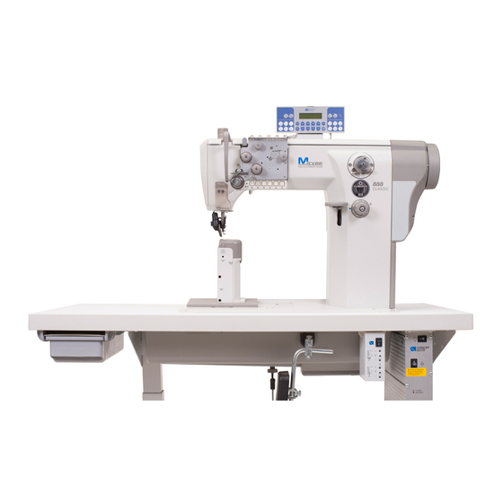
Product description The Dürkopp Adler 888 is a special sewing machine for universal use. • It is a double lockstitch post bed sewing machine . • It has a two step feed. A lower wheel feeder and a driven roller presser feed in two steps, a needle feed feeds in the first step only. -
Page 8: Subclasses
Subclasses 888-160020 Single-needle double lockstitch post bed sewing machine with feed wheel, needle feed with driven roller foot and large hook. - Page 9 888-356152 Single-needle double lockstitch post bed sewing machine with feed wheel, needle feed with driven roller foot and regular hook, electro-magnetic thread cutter, electro-magnetic seam bartacking and sewing foot lifting, equipped with electro motor driven edge trimmer. Short stitch equipment: By pressing a key on the machine head a complete stitch with shortened stitch length is sewn.
-
Page 10: Optional Equipment
Optional equipment The following optional equipments are available for the class 888 : Order No. Optional equipment Subclasses 9880 888101 Integrated sewing light with 2 LED, incl. x x x x x x x x x x x dimmer transformer... -
Page 11: Technical Data
Technical data Noise: Workplace-related emission value in accordance with DIN 45635-48-A-1-KL2 888-160020 LC = _dB (A) Stitch length: _ mm Sewing foot stroke: mm Speed: ____ min Material: 888-160122 LC = _dB (A) Stitch length: _ mm Sewing foot stroke: mm Speed: ____ min... - Page 12 Technical data of the subclasses Subclasses Type of stitch Lock stitch 301 Hook type Number of needles Needle system Needle size (depending on E-No.) [Nm] Max. thread thickness [Nm] 10/3 Stitch length [mm] Forwards Backwards Max. Speed [min 3000 Number of stitches with factory setting [min 2500...
-
Page 13: Operation
Operation Threading the needle thread Caution! Risk of injury! Turn off the main switch. The needle thread may only be threaded with the sewing machine switched off. – Thread the single needle machine according to fig. (A). If the machine is equipped for heavy sewing, wind the thread around the pin (1). -
Page 14: Winding The Hook Thread
Winding the hook thread – Thread the thread according to the picture. – Insert the thread under the knife (1) and tear off by pulling in the arrow direction (2). – Fix the bobbin and press the lever (3) in the direction (4). –... -
Page 15: Adjusting The Thread Tension
Adjusting the thread tension 6.4.1 Adjusting the hook thread tension Caution! Risk of injury! Turn off the main switch. The hook thread tension may only be adjusted with the machine switched off. – Adjust the hook thread tension via the screw (1). Insert a screwdriver through the hole (2). -
Page 16: Adjusting The Needle Thread Tension
6.4.2 Adjusting the needle thread tension Adjusting the pre-tensioner (1) – Adjust the supplementary tensioner (1) so that it has the lowest tension possible, but so high that, when taking out the sewn material after the preceding trimming (when the tensioners (2) and (3) are switched off), the thread is not pulled out of the tensioner (1). - Page 17 Adjusting tensioners (2) and (3) CLASSIC machines with pneumatic control – Through pressing the key (5) the additional tension (2) will be switched off. If the key (5) is pressed anew, the additional tension will be activated again. The connectable additional tension (2) helps in quick adjustment of the needle thread tension, for example in order to get a tight stitch formation with regular seams when sewing different materials.
-
Page 18: Switching On/Off The Thread Tensioners
Switching on/off the thread tensioners ECO and CLASSIC machines with electro-magnetic control – When pulling the hand lever (1) towards the operator, the tensioners (3) and (4) are switched off. – Tensioner (2) is never switched off. Manually controlled machines (without thread trimming) –... -
Page 19: Function Of The Thread Main Tension And The Thread Supplementary Tension In Relation To The Sewing Foot Lifting
6.5.1 Function of the thread main tension and the thread supplementary tension in relation to the sewing foot lifting The thread supplementary tension can, at any time, be switched on or off by actuating key 4 (see chapter 6.5) of the key pad. To this end, the parameter F-147 must be set on “1". -
Page 20: Adjusting The Thread Regulator
Adjusting the thread regulator 1 2 3 4 The thread regulator (2) controls the quantity of needle thread required for stitch formation. The thread regulator must be precisely adjusted for an optimum result. – Loosen the screw (1), shift the thread regulator (2), and tighten the screw (1). -
Page 21: Changing The Needle With Single-Needle Machines With The Hook On The Right
Changing the needle with single-needle machines with the hook on the right Caution! Risk of injury! Replace the needle with the main switch switched off and the motor stopped. – Draw the lever (1) in your direction to loosen the screw fixing the needle. -
Page 22: Changing The Needle With Single-Needle Machines With The Hook On The Left (Machine With Lower Thread Trimmer)
Changing the needle with single-needle machines with the hook on the left (machine with lower material trimming) Caution! Risk of injury! Turn off the main switch. The needle may only be changed with the sewing machine switched off – Draw the lever (1) in your direction to loosen the screw fixing the needle. -
Page 23: Changing The Needle With Double-Needle Machines
Changing the needle with double-needle machines Caution! Risk of injury! Turn off the main switch. The needles may only be changed with the sewing machine switched off. – Loosen the screws (1). – Remove the needle and insert new ones with the needle scarf (2) oriented as shown above [see section (3) or (4)]. -
Page 24: Lifting And Folding The Roller Presser
6.10 Lifting and folding the roller presser Lifting the roller presser with a hand lever – Lift the roller presser by the lever turning (1) in the arrow direction to the stop (the roller presser remains lifted, the lever (1) remains tilted). -
Page 25: Sewing-Foot Pressure
Roller presser folding Caution! Risk of injury! Roller presser folding to be done at main switch off and standing motor. – Lift the roller presser with the hand lever. – Lift the roller presser by pressing in the signed direction. 6.11 Sewing-foot pressure 6.11.1 Setting through the setting wheel –... -
Page 26: Constant Sewing-Foot Pressure Through The Cylinder
6.11.2 Constant sewing-foot pressure through the cylinder – The pressure of the roller presser will be set via the setting wheel (2). – Pull the handle (2) downwards and turn it until the desired operating pressure is shown on the manometer (1). 6.12 Sewing backward (backtacking) Backtacking with the lever –... -
Page 27: Setting The Stitch Length
(3). CLASSIC machines with pneumatic control The special sewing machine 888 is equipped with two setting wheels. Thus, two different stitch lengths can be sewn, that are activated by actuating a key during the sewing process. -
Page 28: Switching On The Safety Clutch At The Hook Blocking
6.14 Switching on the safety clutch at the hook blocking – If the thread gets in the hook way, the hook gets blocked and it is subsequently disconnected from the motor by the safety clutch. Caution! Risk of injury! Turn off the main switch. Switch the safety clutch on, with the sewing machine switched off. -
Page 29: Starting The Manually Controlled Machine With The Clutch Motor
6.15 Starting up the manually controlled machine with a clutch motor – Switch on the motor (1) using the switch (2). – Tread the pedal (3). The motor friction clutch is activated and the sewing machine starts running. – The sewing speed is determined through the pedal (3). –... -
Page 30: Using The Pedal
6.16 Controlling the machine equipped with a positioning motor 6.16.1 Using the pedal The pedal position is scanned by a sensor distinguishing 16 levels. The meaning is given in the table: Pedal position Pedal motion Meaning Over heel fully backwards Command for thread trimming (seam finishing) Over heel slightly backwards Command for foot lifting... -
Page 31: Using The Key
6.16.2 Using the key 10 9 Function Manual sewing backward The machine sews backward stitches as long as the key is being pushed. Needle positioning to the upper or lower position By parameter F-242 (DA321) the following key functions can be defined: 1 = needle up/down 2 = needle up 3 = one stitch... - Page 32 Function 8 and 9 Display for empty bobbin with machines equipped with residual thread monitor (left/right bobbin). LED display “power on” Example of Through the arresting of the pin 11 under the key 1 it is possible to transfer the key 1 function arresting pins: to key 7:...
-
Page 33: Material Edge Trimmer Control
6.17 Sewn material edge trimmer control 6.17.1 Switching on/off edge trimmer Switch on – Push the knob (1) in the arrow (A) direction, or pull the handle (2) in the arrow (B) direction until the trimming knife gets from the initial position (3) to the switch on position (4). -
Page 34: Switching On/Off Material Guide
6.17.2 Switching on/off material guide Switch on – Put the guide (1) in a working position by pushing the lever (2) upwards or by pulling the guide body (3) downwards. Switch off – Shift the ball (4) upwards and to the left. The guide element (5) lifts in a setting position. -
Page 35: Material Guide Adjustment
6.17.3 Material guide adjustment – Adjust the guide element (1) height with a bolt (2). The guide element is lifted, when tightening the bolt, and vice versa. If the bolt (2) strikes the end of the adjustment range, the latter can be widened by the bolt (3), loosening the plate (4) shifting to a different position and its repeated fixing. -
Page 36: Disengaging The Needle Bar With Subclass 888-460522
6.17.4 Disengaging the needle bar with subclass 888-460522 The needle bars are switched on and off with the “L” and “R” keys. – Press the “L” key. The key is illuminated. The left needle bar is switched off. – Sewing. -
Page 37: Positioning Drive Efka Dc1550/Da321G
Positioning drive Efka DC1550/DA321G DA321G control contains all necessary operating elements to switch the functions over and to set the parameters. The operation is possible without the control panel, it is not possible only to program the sewing. It is possible to connect the control panel V810 and V820, which are available as an attachment. -
Page 38: Machine Automatic Function
Sewing with machine with positioning motor Machine automatic functions The machine has the below functions which are automatically performed during the seam sewing depending on: – Pre-selection – Pedal position (according to the machine operator´ s selection) – Working phase of seam sewing Automatic function Pre-selection Needle positioning... -
Page 39: Example Of Machine Operation At Sewing
Automatic function codes are described in the attached drive manufacturer´ s Instruction Leaflet. The drive manufacturer’s Instruction Leaflet for Efka DA321G drive is available on website www.efka.net. Some automatic functions can be preset by means of push buttons. Their description is included in the booklet “Efka Operation Instructions”. -
Page 40: Maintenance
Maintenance Cleaning and checking Caution! Risk of injury! Turn off the main switch. Maintenance may only be carried out with the machine switched off! Maintenance work must be carried out no less frequently than at the intervals given in the tables (see ”operating hours” column). Maintenance intervals may need to be shorter when processing heavy-shedding materials. - Page 41 Maintenance work Explanation Operating to be carried out hours - Clean the oil sump Clean the oil sump (1) of dirt and contaminated oil. (you may use a special vacuum cleaner.) - Clean fan grille Remove lint and pieces of thread from air-intake openings (2) and (3) (e.g.
- Page 42 Maintenance work Explanation Operating to be carried out hours Pneumatic system The water level must not rise to the level of - Check water level in the filter cartridge (1). pressure regulator. - After unscrewing the drain screw (3), the water under pressure will flow out of the water separator (2).
-
Page 43: Lubrication
11.2 Lubrication Caution! Risk of injury! Oil can cause skin eruptions. Avoid protracted contact with the skin. In the event of contact, thoroughly wash the affected area. Caution! The handling and disposal of mineral oils is subject to legal regulation. Deliver used oil to an authorised collection point. - Page 44 Notes:...