Advertisement
Quick Links
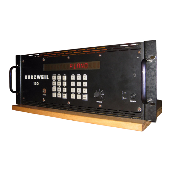
HARDWARE PROGRAMMER'S MODEL AND ADDRESS MAP
This document describes the Kurzweil 150 Fourier Synthesizer from the hardware programmer's point of view. It contains
addresses for all of the hardware registers and brief descriptions of each. At this level the programmer is responsible for all
of the details involved in sound generation, MIDI data decoding (if used), time keeping, front panel display refreshing, and
button scanning.
The reader should be familiar with the documents titled "Model K150 User's Manual", "150FS Version 1.6 Software", and
"Appendix 1 - K150FS System Exclusive Formats" as an example of one successful K150FS operating system
implementation. However this document was prepared for those interested in creating their own operating system perhaps
emphasizing different aspects of additive synthesis than the Kurzweil implementation, which was aimed primarily at realistic
recreations of acoustic instruments and a comprehensive MIDI implementation. For example, frequency envelopes for
partials might be implemented with the time saved by omitting the dynamic partial allocation feature of the Kurzweil
implementation.
SUMMARY OF HARDWARE RESOURCES
The K150FS consists of three boards: the CPU board, the "engine board", and the "sound board". The latter two make up the
sound generator while the CPU board contains all of the memory and other peripheral devices. The overall system resources
are as follows:
1.
68000 CPU running at 10MHz.
2.
Program EPROM up to 128K bytes (4 x 27256 200nS), no wait states.
3.
Scratch RAM (non volatile) 16K, no wait states
4.
Sound EPROM up to 128K bytes (4 x 27256 200nS) or 256K bytes (4 x 27512), 2,5 wait states
5.
Sound RAM (non volatile) 64K, 2,5 wait states
6.
Parameter RAM (non volatile) 2K (old style) or 8K (new style), 2,5 waits
7.
MC6850 serial I/O chip for MIDI In and Out
8.
MC6840 programmable timer chip
9.
16 character 14 segment LED display with decimal points
10. 24 button panel
11. Contact sense for sustain pedal
12. Modulator and demodulator for audio cassette storage
13. General purpose parallel interface (not normally assembled on CPU board)
14. Miscellaneous output port for diagnostics and power-fail shutdown
15. Frequency units converter, functions as a large lookup table
16. Sound generator with 240 sine/noise waves and automatic linear interpolation of amplitude envelopes.
68000 CPU
The 68000 is clocked at 10MHz which is substantially faster than personal computers using the 68000 such as the Atari ST
and Apple Macintosh. Furthermore, for accesses to the primary program EPROM and scratch RAM, there are no wait states.
Programs normally run in Supervisor Mode and there is no special hardware for memory write protection or illegal address
detection. In fact, attempting to read or write a nonexistent address may cause the 68000 to hang due to lack of a DTACK.
The 68000 RESET instruction will reset the sound generator and peripherals.
The 68000 address map is as follows:
ADDRESS RANGE
$000000 - 00FFFF
$010000 - 01FFFF
$020000 - 020003
$024000 - 02000F
$028000 - 02BFFF
$02C000 - 02C7FF
K150FS Programmer's Model
KURZWEIL 150 FOURIER SYNTHESIZER
ALIASES
-023FFF
-027FFF
-02FFFF
FUNCTION
Program EPROM #1, 64K (sockets U55, U57)
Program EPROM #2, 64K (sockets U54, U56)
MC6850 MIDI UART (see below for actual addresses)
MC6840 Timer (see below for actual addresses)
Scratch RAM, 16K
(old style) Parameter RAM, 2K
1
Rev. A 26-APR-88
Advertisement

Related Manuals for Kurzweil K150 - PROGRAMMERS MODEL REV A


Summary of Contents for Kurzweil K150 - PROGRAMMERS MODEL REV A
- Page 1 Kurzweil implementation, which was aimed primarily at realistic recreations of acoustic instruments and a comprehensive MIDI implementation. For example, frequency envelopes for partials might be implemented with the time saved by omitting the dynamic partial allocation feature of the Kurzweil implementation.
- Page 2 ADDRESS RANGE ALIASES FUNCTION $02C000 - 02DFFF -02FFFF (new style) Parameter RAM, 8K $030000 - 0307FF Sound Generator Partial Control Words $030800 -033FFF Sound generator control & status $034000 - 03400A -reserved- $03400B Miscellaneous Status Register $03400C -reserved- $03400D Cassette output D-to-A Register $03400E -037FFF Miscellaneous Control Register...
- Page 3 The primary program EPROM is 16 bits wide and consists of one or two pairs of 27256 EPROMS. U55 and U57 chips must be present since they are addressed beginning at $000000 and contain the startup and interrupt vectors. U54 and U56 are optional and may be used if the program becomes larger than 64K bytes.
-
Page 4: Front Panel
The 6850 register addresses are as follows: $020001 (read) Control Register $020001 (write) Status Register $020003 (read) Received Data Register $020003 (write) Transmit Data Register See also the section below on Miscellaneous I/O for a description of bits which control normal operation and diagnostic loop- back of the MIDI signals. -
Page 5: Sound Generator
patterns to the converter. The low-pass filter cutoff frequency is about 7KHz with a cutoff slope of 12dB/octave so an update rate of 20KHz or more is advisable. This method of producing audio cassette signals allows rounded-off waveforms of known spectral content to be used which can minimize the adverse effects of phase distortion in typical cassette recorders. For best results, the modulation scheme should restrict the signal bandwidth to about 500-2000Hz. - Page 6 Most fundamental is the Phase register. In generating sound, the current content of the phase register is used as an address to lookup in a sine table. If one considers the content of the Phase Register to be an unsigned integer between 0 and 65535, the sine table yields the value: SIN(2*PI*P/65536) where P is the Phase Register content and PI=3.14159...
- Page 7 to the amplitude value. Thus in fast mode (bit 14=0), the LSB of the slope value is 28.6dB per second whereas in slow mode (bit 14=1), it is 1.78dB/sec. Although the slow mode has much more slope resolution than the fast mode, it should only be used for relatively slow slopes since it can cause a low buzzing sound from large amplitude steps at its slow 1.2KHz update rate.
- Page 8 15 years ago. Although Kurzweil programmers use an expensive Hewlett-Packard development system for programming, one can be almost as productive with a personal computer, a MIDI interface, and the suggestions below.
- Page 9 take 2 or 3 iterations to get it functional. Then you will be able to download any software you want into K150FS RAM and execute it. At this point you may wish to write or adapt a "monitor" program which will make debugging of the real software easier or just jump into writing and debugging synthesizer control software.
- Page 10 Sine/Noise Wave Table EPROMs The other table of interest is the sine/noise table. This table was designed to use two 8K by 8 masked ROMs but boards are shipped with 27128 16K by 8 EPROMs installed. 150nS access time is required for these EPROMS. They are in positions U39 (high byte) and U40 on the Sound Board which is the bottom board in the K150FS box.
Need help?
Do you have a question about the K150 - PROGRAMMERS MODEL REV A and is the answer not in the manual?
Questions and answers