Table of Contents
Advertisement
[ 1 ] GENERAL . . . . . . . . . . . . . . . . . . . . . . . . . . . . . . . . . . . . . . . . . . . . . . . . 1-1
[ 2 ] SPECIFICATIONS . . . . . . . . . . . . . . . . . . . . . . . . . . . . . . . . . . . . . . . . . . 2-1
[ 3 ] CONSUMABLE PARTS . . . . . . . . . . . . . . . . . . . . . . . . . . . . . . . . . . . . . 3-1
[ 4 ] EXTERNAL VIEWS AND INTERNAL STRUCTURE . . . . . . . . . . . . . . . 4-1
[ 5 ] UNPACKING AND INSTALLATION . . . . . . . . . . . . . . . . . . . . . . . . . . . . 5-1
[ 6 ] ADJUSTMENTS . . . . . . . . . . . . . . . . . . . . . . . . . . . . . . . . . . . . . . . . . . . 6-1
[ 7 ] SIMULATIONS . . . . . . . . . . . . . . . . . . . . . . . . . . . . . . . . . . . . . . . . . . . . 7-1
[ 8 ] USER PROGRAM . . . . . . . . . . . . . . . . . . . . . . . . . . . . . . . . . . . . . . . . . . 8-1
[ 9 ] TROUBLE CODE LIST . . . . . . . . . . . . . . . . . . . . . . . . . . . . . . . . . . . . . . 9-1
[10] MAINTENANCE . . . . . . . . . . . . . . . . . . . . . . . . . . . . . . . . . . . . . . . . . . . 10-1
[11] DISASSEMBLY AND ASSEMBLY . . . . . . . . . . . . . . . . . . . . . . . . . . . . 11-1
[12] FLASH ROM VERSION UP PROCEDURE . . . . . . . . . . . . . . . . . . . . . 12-1
[13] ELECTRICAL SECTION . . . . . . . . . . . . . . . . . . . . . . . . . . . . . . . . . . . . 13-1
Parts marked with "
" are important for maintaining the safety of the set. Be sure to replace these parts with specified
ones for maintaining the safty and performance of the set.
CONTENTS
SHARP CORPORATION
CODE: 00ZAR205//A1E
DIGITAL COPIER
AR-160
AR-161
AR-200
AR-205
MODEL
This document has been published to be used
for after sales service only.
The contents are subject to change without notice.
AR-205
Advertisement
Chapters
Table of Contents

Related Manuals for Sharp AR-160


Summary of Contents for Sharp AR-160
- Page 1 AR-205 CODE: 00ZAR205//A1E DIGITAL COPIER AR-160 AR-161 AR-200 AR-205 MODEL CONTENTS [ 1 ] GENERAL ..........1-1 [ 2 ] SPECIFICATIONS .
- Page 2 AR-205 Warning! This product is a class A product. If it is operated in households, offices or similar surroundings, it can produce radio interferences at other appliances, so that the user has to take adequate countermeasures. CLASS 1 LASER PRODUCT VAROITUS! LAITTEEN KÄYTTÄMINEN MUULLA KUIN TÄSSÄ...
-
Page 3: Table Of Contents
AR-205 CONTENTS [ 1 ] GENERAL [ 8 ] USER PROGRAM ....... 1-1 . -
Page 4: Note For Servicing
7) If water or a metal piece drops into the machine, turn off the print function and the Fax function are options.) power switch, disconnect the power plug, then remove the 10)There are some sharp edges inside the machine. Be careful not to dropped thing. injure your fingers when servicing. -
Page 5: Copy Mode
Document replacement 16 sheets/min (A4 8.5" 11" (2) Continuous copy speed (Sheets/min) speed normal copy) a. AR-160/161 Document set/Paper feed Face up, Center reference, Paper direction feed from the top Enlargement Reduction Paper size... - Page 6 Paper feed Single except for recycled paper Standard/Option Standard provision (AR-205 only) (D (3) Option paper feed unit S enable only when RSPF is installed) Not available for AR-160/161/200 1-step paper feed 2-step paper feed unit unit N. Paper exit/finishing...
- Page 7 The image at the center is erased when S. External view copying. (Adjustable in 0 20mm by the user program.) External dimensions 470 mm (AR-160/161) Margin shift Binding margin is made at the left edge of the 523mm (AR-200/205) set documents. Occupying area (W 531mm P.
-
Page 8: Supply System Table
AR-205 [3] CONSUMABLE PARTS 1. Supply system table A. USA, CANADA Name Content Life Model name Package Remark Developer cartridge (Black) Toner/developer cartridge AR-200TD Life setting by A4 (8.5" (Toner 610g, Developer 395g) (*1 AR-200TD-J) 11") 6% document Vinyl bag Drum cartridge Drum cartridge AR-200DR... - Page 9 AR-205 C. Europe / Australia / New Zealand / Middle East / Africa / CIS Name Content Life Model name Package Remark Developer cartridge (Black) Toner/developer cartridge AR-200DC Life setting by A4 6% (Toner 610g, Developer 395g) document Vinyl bag Drum cartridge Drum cartridge AR-200DM...
-
Page 10: Production Number Identification
AR-205 2. Environment conditions 3. Production number identification A. Transport condition <TD cartridge> The label on the drum cartridge shows the date of production. (1) Transport conditions Destination Serial number Production (00001-99999) month January Indicates production in China. The end digit of production year September : Destination October... -
Page 11: Consumable Parts Recycling Procedure
AR-205 4) Remove the DV blade. 4. Consumable parts recycling procedure Note: Be sure to remove adhesive completely. A. TD cartridge Remove adhesive together with the base PET. 1) Check the external view. Note: Be careful especially of breakage of the pins and the ATC sensor connector shown below. -
Page 12: Drum Unit
AR-205 11) Face the toner supply port of the toner box upward with the 17) Shake the developing unit 5 times left and right horizontally. toner bottle put straight, and insert the supply hose into the toner 18) Check the distribution state of developer on the MG roller. supply port. - Page 13 AR-205 2) Remove the drum cover. (4 Lock Tabs) 6) Remove the cleaning blade. 3) Remove the drum fixing plate and the photoconductor drum. Note: Dispose the cleaning blade which was removed. (Note) Dispose the drum fixing plate which was removed. 7) Clean the cleaning section and the waste toner pipe to remove waste toner completely with a vacuum cleaner.
- Page 14 AR-205 11) Attach the main charger. 12) Attach the drum fixing plate and the photoconductor drum. Apply grease to the inside of the photoconductor drum. (Dia. 2) 13) Attach the detection gear. • Note: The detection gear is not installed to the drum cartridge packed with the main body.
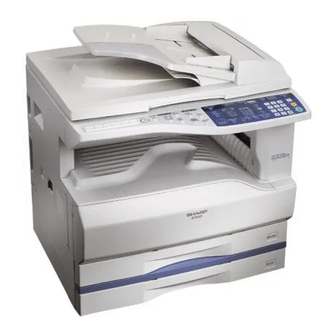
- Page 15 AR-205 [4] EXTERNAL VIEWS AND INTERNAL STRUCTURES 1. Appearance Original cover Original table (OC table) Handles Power switch Operation panel Paper output tray Front cover Paper tray Side cover Side cover handle Bypass tray guides Bypass tray Bypass tray extension Second cassette AR-200/205 only 2.
-
Page 16: Operation Section
AR-205 3. Operation Section 10 11 12 15 16 20 21 22 23 24 29 30 Not used for the copier features. Interrupt key and indicator Copy quantity display ZOOM indicator Copy ratio display key Zoom keys PAPER SIZE ENTER key AUDIT CLEAR key PAPER SIZE indicators Alarm indicators... -
Page 17: Motor, Solenoid, Clutch
AR-205 4. Motor, solenoid, clutch Name Code Function, operation Exhaust fan motor Cools the inside of the machine. Shifter motor SHTM Shifts the paper exit tray. (AR-161/200/205) Toner motor Toner supply Mirror motor Drives the optical mirror base (scanner unit). Duplex motor Switchback operation and paper exit motor in duplex. -
Page 18: Sensor, Switch
AR-205 5. Sensor, switch Name Code Function, operation Mirror home position sensor MHPS Detects the mirror (scanner unit) home position. Document size sensor DSIN Paper size detection Toner density sensor Toner quantity detection Paper exit sensor (paper exit side) POD1 Detects paper exit. -
Page 19: Pwb Unit
AR-205 6. PWB unit Name Function, operation Copy lamp invertor PWB Copy lamp control Power PWB AC power input/DC power control High voltage PWB High voltage control CCD sensor PWB Image scanning Main PWB (MCU) Machine control/Image process Paper exit interface PWB Paepr exit, finishing control Tray interface PWB Paper tray control... -
Page 20: Cross Sectional View
AR-205 7. Cross sectional view Name Function/Operation Copy lamp Image radiation lamp Copy lamp unit Operates in synchronization with No. 2/3 mirror unit to radiate documents sequentially. LSU unit Converts image signals into laser beams to write on the drum. Lens unit Reads images with the lens and the CCD. -
Page 21: Installing Conditions
AR-205 [5] UNPACKING AND 3. Installation of developing cartridge INSTALLATION 1) Open the manual paper feed tray. 1. Installing conditions 1) Copier installation Do not install your copier in areas that are: • damp, humid, or very dusty • exposed to direct sunlight •... -
Page 22: Removal And Storage Of Fixing Screw
AR-205 6) Remove the pawls (3 positions) of the protective cover at the rear 4. Removal and storage of fixing screw side. 1) Lift the knob and gently pull out the tray. 7) Remove the protective cover. 2) Hold the paper pressure plate and turn the fixing screw in the •... -
Page 23: Changing The Copy Paper Size In The Tray
AR-205 10) Use the ORIGINAL SIZE ENTER key to select the paper size 5. Changing the copy paper size in the tray which is set. 1) Gently lift and pull out the paper tray until it stops. • Each time the ORIGINAL SIZE ENTER key is pressed, a 2) Push the pressure plate down until it locks in place. -
Page 24: Adjustment Item List
AR-205 [6] ADJUSTMENTS 1. Adjustment item list Section Adjustment item Adjustment procedure/SIM No. Process Developing doctor gap adjustment Developing doctor gap adjustment section MG roller main pole position adjustment MG roller main pole position adjustment Developing bias voltage output adjustment Main charger voltage output adjustment Mechanism Image lead edge position adjustment... - Page 25 AR-205 (3) Developing bias voltage adjustment B. Mechanism section • Note: Use a digital multi-meter with an internal resistance of (1) Image lead edge position adjustment (SIM 50-1) 10M or more. a. OC image lead edge position adjustment 1) Set the digital multi-meter range to DC700V. Note: In advance to this adjustment, the sub scanning magnification 2) Put the test rod of the digital multi-meter on the developing bias ratio adjustment must be performed.
- Page 26 AR-205 9) Measure the distance H between the paper lead edge and the <Adjustment specification> image print start position. Set the image print start position set Adjustment Spec value (Exposure display <EXP1> ON) again. Set value mode value range • 1 step of the set value corresponds to about 0.127mm shift.
- Page 27 AR-205 c. Rear edge void adjustment <Adjustment specification> 1) Set a scale as shown in the figure below. Specifi- Mode Set value cation range A4(8.5" x 11") Add 1: Single: Paper off Selected 0.127mm Center SIM 50-10 center tray ON shift to R 2.0mm side.
- Page 28 AR-205 2) Loosen the copy lamp unit wire fixing screw. 5) Without moving the scanner drive pulley shaft, manually turn the scanner drive pulley until the positioning plate is brought into con- tact with No. 2/3 mirror base unit, then fix the scanner drive pulley. 6) Put No.
-
Page 29: Rear Side
AR-205 4) Loosen the mirror base drive pulley fixing screw on the front frame (3) Main scanning direction (FR direction) distortion side or on the rear frame side. adjustment This adjustment must be performed in the following cases: • When La < Lb •... - Page 30 AR-205 1) Making of a test sheet • When La > Lb Make test sheet by drawing parallel lines at 10mm from the both Shift the mirror base B rail upward by the half of the difference ends of A3 (11" x 17") white paper as shown below. (These lines of La –...
- Page 31 AR-205 <Adjustment specification> Note: Since the printed copy is used as a test chart, put the scale in parallel with the edge lines. Note: A judgement must be made with 200mm width, and must not be made with 100mm width. 2) Set the test chart on the SPF and make a normal (100%) copy.
- Page 32 Single: Add 1: 1 ~ 99 off center Center 3.0mm 50-16 0.1mm shift to <Other than AR-160> mode R side Duplex: 1) Execute SIM 41-2. (SPF Reduce 1: Center 3.5mm 2) Set A3 (11" x 17") paper on the OC table.
- Page 33 AR-205 6) Make a copy and check that the specification below is satisfied. <Adjustment specification> Density Display Exposure Sharp Gray Set value mode lamp level Chart output range Auto Auto — "3" is slightly The greater the 1 ~ 99 copied.
-
Page 34: Entering The Simulation Mode
Developing counter display Self printing mode Developing preset counter value display Printer Flash ROM Data Download (Japan only) A: Not used in the AR-160/161/200/205. SPF counter display B: Only when an option is installed. Paper feed counter display C: AR-205 only... -
Page 35: Contents Of Simulations
AR-205 4. Contents of simulations Main Initial Contents Details of operation Set range code code value Mirror unit operation check Used to execute scanning at the speed corresponding to the set 100% 200% magnification ratio. Key operation Display Changing the magnification ratio: Set magnification ratio: Fixed magnification ratio key Fixed magnification ratio LED... - Page 36 AR-205 Main Initial Contents Details of operation Set range code code value Shifter job separator Used to check the sensors state in the shifter job separator with the sensor operation check LED on the operation panel. Display <Lighting at sensor ON> Shifter HP sensor: Machine position JAM LED Job separator HP sensor: SPF JAM LED Paper exit full sensor: Second cassette position JAM LED...
- Page 37 AR-205 Main Initial Contents Details of operation Set range code code value Shifter Home Position Used to drive the shifter motor check Key operation Feed: Exposure up key or "3" key Return: Exposure down key or "4" key Move to Home Position: Magnification ratio display key or "5" key Aging with warmup time Execute the simulation input with the copier side cover open, then close display...
- Page 38 AR-205 Main Initial Contents Details of operation Set range code code value Maintenance cycle setting Used to display the currently set maintenance cycle at the numbers shown at right. When the set value is entered and the start key is pressed, the set value is stored.
- Page 39 AR-205 Main Initial Contents Details of operation Set range code code value Trouble memory display Used to display the actually occurred trouble codes on the display on the operation panel. When the start key is pressed during the main code display, the sub code is displayed.
- Page 40 AR-205 Main Initial Contents Details of operation Set range code code value Option switch display Used to display the installed option on the operation panel. (The LED corresponding to the installed option is lighted.) Key operation Display Display select: <Lighting with an option installed> Magnification When “A”...
- Page 41 Key operation/Display 0: AL-1600 11: AR-N200 1: AL-1610 12: AR-N205 2: AL-1620 13: AL-1621 3: AL-1640/AL-1641 14: AL-1650 4: AR-160/AR-S160 15: AL-1670 5: AR-161/AR-S161 16: AR-F200 6: AR-200S 17: DM-2000 7: AR-200/AR-S200 18: DM-2005 8: AR-205/AR-S205 19: DM-2010...
- Page 42 Used to read the document sensor input value with paper and perform adjustment the sensor detection level adjustment. For the adjustment procedure of <Other than AR-160> the document sensor input value, refer to the previous descriptions. Document sensor light Used to display the light reception level and the detection level of the reception level display document sensor.
- Page 43 AR-205 Main Initial Contents Details of operation Set range code code value Main scanning (front/rear) After completion of warmup, shading is performed and the currently set direction magnification main scanning (front/rear) direction magnification ratio adjustment and ratio adjustment the OC mode document center off adjustment are performed. For the (Copy/FAX/OC-SPF adjustment procedure, refer to the previous descriptions.
- Page 44 AR-205 Main Initial Contents Details of operation Set range code code value Copy image position After completion of warmup, shading is performed and the currently set adjustment value is displayed. For the adjustment procedure, refer to the previous descriptions. Key operation Display Adjustment mode Auto: Copy lead edge adjustment...
- Page 45 AR-205 Main Initial Contents Details of operation Set range code code value Duplex rear edge void After completion of warmup, shading is performed and currently set adjustment value is displayed. Key operation Display Adjustment mode select: Auto: SPF/R-SPF rear edge void Exposure mode select key Set value: Manual: R-SPF off center...
-
Page 46: List Of User Programs
AR-205 [8] USER PROGRAMS Program Program Description name The user programs allow the parameters of certain functions to be set, Image Enables or disables image rotation changed, or canceled as desired. rotation in (180˚) of the front side in one-sided to duplex two-sided copying or two-sided to one- 1. - Page 47 AR-205 For example, to change the setting of the auto power shut-off timer to In European countries, the default setting of the preheat mode is 1 60 min., press key 2. (30 sec.). For other programs, factory-default settings in these countries are same to those shown above with an asterisk ( ).
- Page 48 AR-205 If you have pressed the 0 key in step 1, an account number will appear in the copy quantity display. Proceed to step 3). If you have pressed key 1, all account numbers will be deleted. Proceed to step 5). 3) Use the copy ratio display ( ) key to select the account number to be deleted.
-
Page 49: Trouble Code List
AR-205 [9] TROUBLE CODE LIST 1. Trouble code list Trouble Operation control PWB communication trouble Trouble content code Operation control PWB communication trouble E-Sort board communication trouble (Protocol) E-Sort board trouble Operation control PWB communication trouble (Parity) E-Sort ASIC error Operation control PWB communication trouble E-Sort CODEC error (Overrun) - Page 50 AR-205 Main Main Detail of trouble Detail of trouble code code code code Check and Replace the E-Sort PWB. Cause A image rotating RAM abnormality remedy Check grounding of the machine. is detected in the E-Sort PWB. Control circuit hung up due to Content E-Sort PWB CODEC error noises...
- Page 51 AR-205 Main Main Detail of trouble Detail of trouble code code code code Check and Check the connectors and harness Check and Improper connection of the LSU remedy of the E-Sort PWB and the MCU remedy connector PWB. Check the polygon motor Check grounding of the machine.
- Page 52 AR-205 Main Main Detail of trouble Detail of trouble code code code code Check and Check the heater lamp blinking Content Mirror base return trouble remedy with SIM 5-2. Detail The mirror home position (MHPS) When the lamp blinks normally: does not turn on though the mirror Check the thermistor and the base returning is completed during...
- Page 53 AR-205 Main Main Detail of trouble Detail of trouble code code code code Cause EEPROM failure Check and Check the connectors and harness Installation of uninitialized EEPROM remedy of the operation control PWB and MCU PWB EERPOM access the MCU PWB. circuit failure Check grounding of the machine.
- Page 54 AR-205 Main Main Detail of trouble Detail of trouble code code code code Content Operation control PWB Content FAX control PWB communication communication trouble (Time-out) trouble (Parity) Detail Communication trouble between Detail Communication trouble between MCU and the operation PWB MCU and FAX control PWB (Time-out error) (Parity error)
- Page 55 AR-205 Main Main Detail of trouble Detail of trouble code code code code Check and Check connector/harness between Cause Bad connection of printer PWB remedy FAX control PWB and MCU PWB. connector Check grounding of the machine. Defective harness between printer Check FAX control PWB ROM.
-
Page 56: Maintenance Table
AR-205 [10] MAINTENANCE 1. Maintenance table : Check (Clean, adjust, or replace when required.) : Clean : Replace : Adjust : Lubricate When calling or Unit name Part name 150k replacing the kit Transfer section Charger unit Transfer paper guide Optical section Lamp unit Reflector... - Page 57 AR-205 B. Charger wire [11] DISASSEMBLY AND Installation: The spring tip must be between two reference ribs. ASSEMBLY • The charger wire must be free from twist or bending. • Be sure to put the charger wire in the V groove. WARNING: Before performing the disassembly procedure, be sure to remove the power cord to prevent against an electric shock.
-
Page 58: Optical Section
AR-205 2. Optical section Content Table glass Copy lamp unit Copy lamp Lens unit A. Table glass C. Copy lamp B. Copy lamp unit Disassembly: Be sure to put No. 2/3 mirror unit to the positioning plate (A). Assembly: Put the notched surface of wire holder (3) downward, tighten temporarily, and install. -
Page 59: Fusing Section
AR-205 B. Thermostat Lens unit attachment reference Attach the lens unit so that the lens unit number on the lens adjustment plate is aligned with the scribe line on the base plate. Example: Lens unit number –2.8 Attach the lens unit at 2 scales in the paper exit direc- tion from the reference line. - Page 60 AR-205 Assembly: Put the paper guide earth spring (A) under the paper E. Upper heat roller guide (B) before fusing. Disassembly: There are three pawls on the fusing cover. Remove the screws and slide the fusing cover to the right to remove.
-
Page 61: Paper Exit Section
AR-205 G. Lower heat roller A. Front cabinet unit, right cabinet disassembly Assembly: When installing the paper guide (3) before fusing, tighten the paper guide fixing plate so that the paper guide fixing plate (2) is in contact with the frame bottom section (A) under fusing. - Page 62 AR-205 C. Paper exit unit E. Paper exit roller D. Transport roller Assembly: Insert the spring pin so that the waveform (A) of the spring pin faces in the longitudinal direction of the paper exit drive gear long hole (B). Be sure to insert two ribs (C) into the groove (D).
-
Page 63: Mcu
AR-205 6. Optical frame unit Content Optical frame unit A. Optical frame unit Installation: Install the optical unit in the sequence shown above. 5. MCU 7. LSU Content Content LSU unit A. MCU disassembly A. LSU unit Note: When replacing the MCU PWB, be sure to replace the EEPROM of the MCU PWB to be replaced. -
Page 64: Tray Paper Feed Section/Paper Transport Section
AR-205 Assembly: Do not miss the door lock pawl. • Adjustment: Image lead edge position adjustment • Image left edge position adjustment • Paper off-center adjustment 8. Tray paper feed section/Paper transport B. Drive unit section Assembly: Move down the clutch pawl as shown below, and avoid the clutch and install. -
Page 65: Manual Multi Paper Feed Section
AR-205 E. Paper feed clutch/Paper feed roller (Semi-circular roller) C. Solenoid (paper feed solenoid, resist roller solenoid) D. Resist roller clutch/Resist roller 9. Manual multi paper feed section Content Manual multi paper feed section Manual transport clutch Manual paper feed clutch Manual transport roller/Manual paper feed roller Multi feed solenoid A. - Page 66 AR-205 Disassembly: Set up the cam transmission arm (2), and remove it. B. Manual transport clutch Assembly: Install so that the cam transmission arm (2) is under the roller arm (A). C. Manual paper feed clutch Disassembly: Set up the shutter arm (1) then remove it. Assembly: Install so that the boss section of the fulcrum arm (2) comes between ribs.
-
Page 67: Power Section
AR-205 10. Power section D. Manual transport roller/Manual paper feed roller Content Installation: Be careful of the installing direction of the manual Power unit transport roller (4). A. Power unit E. Multi feed solenoid Assembly: Install so that the latches (A) and (B) move smoothly. 11 –... -
Page 68: Developing Section
AR-205 11. Developing section Adjustment: Developing doctor gap adjustment Contents D. MG roller Waste toner box Developing box Developing doctor MG roller A. Waste toner box B. Developing box C. Developing doctor Adjustment: MG roller main pole position adjustment 11 – 12... -
Page 69: Process Section
AR-205 B. MC holder unit 12. Process section Contents Drum unit MC holder unit Cleaning blade A. Drum unit Assembly: When installing the drum cover (1), be sure to engage the transport screw gear (A) rib and the detection gear (B). C. - Page 70 AR-205 7) Communication port/communication speed setting [12] FLASH ROM VERSION UP Select “Comport” in the option menu, and select the most PROCEDURE suitable item with consideration of PC environment, work time, etc. 1. MCU/E-SORT A. Tool Machine Operates on Windows 95/98. Level converter (UKOG-0002QSZZ) (with serial cable) Level converter (UKOG-0003QSZZ) (without serial cable) (Serial cable)
- Page 71 AR-205 9) Select the data for MCU to be transferred. 2. PRINTER CONTROL PWB FIRMWARE VERSION UP <With an option installed> A. Cases where flash memory rewriting is required In the following cases, the program in the printer control PWB flash memory must be rewritten.
- Page 72 AR-205 [13] ELECTRICAL SECTION 1. BLOCK DIAGRAM 13 – 1...
- Page 73 AR-205 AR-205 2. ACTUAL WIRING DIAGRAM ACTUAL WIRING DIAGRAM 1/3 13 – 2 13 – 3...
- Page 74 AR-205 AR-205 ACTUAL WIRING DIAGRAM 2/3 13 – 4 13 – 5...
- Page 75 AR-205 AR-205 ACTUAL WIRING DIAGRAM 3/3 13 – 6 13 – 7...
- Page 76 AR-205 COPYRIGHT © 1999 BY SHARP CORPORATION All rights reserved. Printed in Japan. No part of this publication may be reproduced, stored in a retrieval system, or transmitted, in any form or by any means, electronic, mechanical, photocopying, recording, or otherwise, without prior written permission of the publisher.