
Related Manuals for MSI K7N2 Delta2 - Motherboard - ATX


Summary of Contents for MSI K7N2 Delta2 - Motherboard - ATX
- Page 1 K7N2 Delta2 Series MS-6570E (v1.X) ATX Mainboard English / French / German G52-M6570E8...
- Page 2 Manual Rev: 1.3 Release Date: August 2004 FCC-B Radio Frequency Interference Statement This equipment has been tested and found to comply with the limits for a class B digital device, pursuant to part 15 of the FCC rules. These limits are designed to provide reasonable protection against harmful interference when the equipment is operated in a commercial environment.
-
Page 3: Copyright Notice
Copyright Notice The material in this document is the intellectual property of MICRO-STAR INTERNATIONAL. We take every care in the preparation of this document, but no guarantee is given as to the correctness of its contents. Our products are under continual improvement and we reserve the right to make changes without notice. -
Page 4: Technical Support
Alternatively, please try the following help resources for further guidance. † Visit the MSI homepage & FAQ site for technical guide, BIOS updates, driver updates, and other information: http://www.msi.com.tw & http://www.msi. - Page 5 CONTENTS FCC-B Radio Frequency Interference Statement ............ii Copyright Notice ......................iii Revision History ......................iii Technical Support ......................iv Safety Instructions ......................iv English ........................E-1-1 1. Getting Started ....................E-1-3 2. Hardware Setup .................... E-2-1 3. BIOS Setup ..................... E-3-1 Français ........................
- Page 6 K7N2 Delta2 Series (MS-6570E v1.X) ATX mainboard English...
- Page 7 MS-6570E ATX Mainboard E-1-2...
-
Page 8: Getting Started
Getting Started Chap t er 1 . Ge tting Started Getting Started Thank you for purchasing the K7N2 Delta2 Series (MS-6570E v1.X) ATX mainboard. The K7N2 Delta2 Series mainboard is based ® ® on NVIDIA nForce™ 2 Ultra 400/IGP & NVIDIA Gigabit MCP/RAID MCP for optimal system efficiency. -
Page 9: Mainboard Specifications
MS-6570E ATX Mainboard Mainboard Specifications † Supports Socket A (Socket-462) for AMD Athlon/Athlon XP /Duron processors † Supports from 1100MHz to FSB 400 Athlon XP 3200+ processor (For the latest information about CPU, please visit http://www.msi.com.tw/program/ products/mainboard/mbd/pro_mbd_cpu_support.php) Chipset † NVIDIA ®... - Page 10 Getting Started On-Board Peripherals † On-Board Peripherals include: - 1 f l o p p y p o r t s u p p o r t s 1 F D D w i t h 3 6 0 K , 7 2 0 K , 1 . 2 M , 1 . 4 4 M a n d 2.88Mbytes - 1 serial port - 1 VGA port (IGP only)
- Page 11 MS-6570E ATX Mainboard NV RAID (Software) † Supports 2 serial ATA plus 1 ATA 133 - RAID 0, or 1, 0+1, JBOD is supported - Booting from RAID - Cross controller RAID support - Rebuilding on the Fly - Spare Disk Allocation †...
-
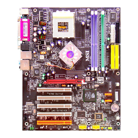
Page 12: Mainboard Layout
Getting Started Mainboard Layout Top : mouse Bottom: keyboard SOCKET 462 Top : Parallel Port Bottom: COM A VGA (Optional) T: SPDIF Out B: USB ports nVIDIA nFORCE2 T: LAN jack Ultra 400/ B: USB ports Line-In Line-Out B:Mic AGP Slot PCI Slot 1 SATA1 NVIDIA... - Page 13 MS-6570E ATX Mainboard Top : mouse Bottom: keyboard SOCKET 462 Top : Parallel Port Bottom: COM A VGA (Optional) T: SPDIF Out B: USB ports nVIDIA nFORCE2 T: LAN jack Ultra 400/ B: USB ports Line-In Line-Out B:Mic Line-Out Line-Out B:SPDIF Out AGP Slot PCI Slot 1...
-
Page 14: Packing Contents
Getting Started Packing Contents MSI Driver/Utility CD SATA Cable (Optional) MSI motherboard Round Cable of Power Cable D-Bracket 2 (Optional) IDE Devices Round Cable of Back IO Shield User’ s Guide Floppy Disk E-1-9... -
Page 15: Hardware Setup
Hardware Setup Chapter 2. Hardware Setup Hardware Setup This chapter tells you how to install the CPU, memory modules, and expansion cards, as well as how to setup the jumpers on the mainboard. Also, it provides the instructions on connecting the periph- eral devices, such as the mouse, keyboard, etc. -
Page 16: Quick Components Guide
MS-6570E ATX Mainboard Quick Components Guide CPU, p.2-3 JPW1, p.2-8 CPU_FAN1, p.2-15 DDR DIMMs, p.2-6 JCI1, p.2-20 FDD1, p.2-15 Back Panel JWR1, p.2-8 I/O, p.2-9 IDE1/2, p.2-16 NB_FAN1, p.2-15 S_FAN2, p.2-15 SATA1/2, p.2-17 JLED1, p.2-22 S_FAN1, p.2-15 JCD1, p.2-19 JBAT1, p.2-23 JAUD1, p.2-19 JIR1, p.2-22 J1394_1/2/3, p.2-21... -
Page 17: Cpu Core Speed Derivation Procedure
If you do not find the heat sink and cooling fan, contact your dealer to purchase and install them before turning on the computer. For the latest information about CPU, please visit http://www.msi.com.tw/ program/products/mainboard/mbd/pro_mbd_cpu_support.php. MSI Reminds You... -
Page 18: Cpu Installation Procedures For Socket 462
MS-6570E ATX Mainboard CPU Installation Procedures for Socket 462 Please turn off the power and unplug the power cord before installing the CPU. Open Lever Pull the lever sideways away Sliding 90 degree from the socket. Make sure to Plate raise the lever up to a 90-degree angle. - Page 19 MSI Reminds You... Please apply some heat sink paste on top of CPU to dissipate the heat more effectively.
- Page 20 Please note that the system will support dual channel DDR when you install DDR modules on DIMM1(purple slot) and DIMM3(green slot), or DIMM2(purple slot) and DIMM3(green slot). For the updated supporting memory modules, please visit http://www.msi. com.tw/program/products/mainboard/mbd/pro_mbd_trp_list.php. DDR 1 DDR 2...
-
Page 21: Installing Ddr Modules
The plastic clip at each side of the DIMM slot will automatically close. Notch Volt MSI Reminds You... You can barely see the golden finger if the module is properly in- serted in the socket. E-2-7... -
Page 22: Power Supply
JPW1 Pin Definition SIGNAL JPW1 MSI Reminds You... 1. These two connectors connect to the ATX power supply and have to work together to ensure stable operation of the mainboard. 2. Power supply of 300 watts (and above) is highly recommended for system stability. -
Page 23: Back Panel
Hardware Setup Back Panel The back panel provides the following connectors: K7N2 Delta2 Series Type I SPDIF Out Parallel (coaxial) Mouse L-In L-Out USB Ports Keyboard COM A VGA (Optional) K7N2 Delta2 Series Type II L-In L-Out SPDIF Out Parallel (coaxial) Mouse USB Ports... - Page 24 MS-6570E ATX Mainboard Mouse/Keyboard Connector ® The mainboard provides a standard PS/2 mouse/keyboard mini DIN connector ® ® for attaching a PS/2 mouse/keyboard. You can plug a PS/2 mouse/keyboard directly into this connector. The connector location and pin assignments are as follows: Pin Definition SIGNAL DESCRIPTION...
-
Page 25: Serial Port Connector
Hardware Setup Serial Port Connector The mainboard offers one 9-pin male DIN connector as the serial port. The port is a 16550A high speed communication port that sends/receives 16 bytes FIFOs. You can attach a serial mouse or other serial devices directly to the connector. Pin Definition 1 2 3 4 5 SIGNAL... - Page 26 MS-6570E ATX Mainboard LAN (RJ-45) Jack The mainboard provides 1 standard RJ-45 jack for connection to single Local Area Network (LAN). This Giga-bit LAN enables data to be transferred at 1000, 100 or 10Mbps. You can connect a network cable to either LAN jack. Giga-bit LAN Pin Definition SIGNAL DESCRIPTION...
- Page 27 Speaker Out ( in 6CH+S/PDIF) S/PDIF Out-Optical (in 6CH+S/PDIF) MSI Reminds You... For advanced audio application, Realtek ALC655 audio chip is pro- vided to offer support for 6-channel audio operation and can turn rear audio connectors from 2-channel to 4-/6-channel audio.
- Page 28 MS-6570E ATX Mainboard Parallel Port Connector: LPT1 The mainboard provides a 25-pin female centronic connector as LPT. A parallel port is a standard printer port that supports Enhanced Parallel Port (EPP) and Ex- tended Capabilities Parallel Port (ECP) mode. Pin Definition SIGNAL DESCRIPTION STROBE...
- Page 29 CPU fan control. Sensor Sensor Sensor Sensor +12V +12V +12V +12V NB_FAN1 S_FAN1 S_FAN2 CPU_FAN1 MSI Reminds You... 1. Always consult the vendors for proper CPU cooling fan. 2. Please refer to the recommended CPU fans at AMD ® official website. E-2-15...
- Page 30 IDE2 (Secondary IDE Connector) IDE2 can also connect a Master and a Slave drive. MSI Reminds You... If you install two hard disks on cable, you must configure the second drive to Slave mode by setting its jumper. Refer to the hard disk documentation supplied by hard disk vendors for jumper setting instructions.
- Page 31 Take out the dust cover and connect to the hard disk devices Connect to serial ATA ports MSI Reminds You... Please do not fold the serial ATA cable in a 90-degree angle, which will cause the loss of data during the transmission. E-2-17...
- Page 32 MS-6570E ATX Mainboard Front Panel Connectors: JFP1 & JFP2 The mainboard provides two front panel connectors for electrical connection ® to the front panel switches and LEDs. JFP1 is compliant with Intel Front Panel I/O Connectivity Design Guide. Power Power Speaker Switch JFP2...
- Page 33 Left channel audio signal to front panel AUD_RET_L Left channel audio signal return from front panel MSI Reminds You... If you don’t want to connect to the front audio header, pins 5 & 6, 9 & 10 have to be jumpered in order to have signal output directed to the rear audio ports.
- Page 34 MS-6570E ATX Mainboard Chassis Intrusion Switch Connector: JCI1 This connector is connected to a 2-pin chassis switch. If the chassis is opened, the switch will be short connected. The system will record this status and show a warning message on the screen. To clear the warning, you must enter the BIOS utility and clear the record.
- Page 35 Hardware Setup IEEE 1394 Connectors: J1394_1, J1394_2, J1394_3 (optional) The mainboard provides three 1394 pin headers that allow you to connect IEEE 1394 ports via an external IEEE1394 bracket (optional). J1394_1/J1394_2/J1394_3 Pin Definition SIGNAL SIGNAL TPA+ TPA- Ground Ground TPB+ TPB- Cable power Cable power...
- Page 36 MS-6570E ATX Mainboard D-Bracket™ 2 Connector: JLED1 The mainboard comes with a JLED1 connector for you to connect to D-Bracket™ 2. D-Bracket™ 2 is a USB Bracket that supports both USB1.1 & 2.0 spec. It integrates four LEDs and allows users to identify system problem through 16 various combina- tions of LED signals.
- Page 37 JBAT1 Keep Data Clear Data MSI Reminds You... You can clear CMOS by shorting 2-3 pin while the system is off. Then return to 1-2 pin position. Avoid clearing the CMOS while the system is on; it will damage the mainboard.
-
Page 38: Pci Interrupt Request Routing
MS-6570E ATX Mainboard Slots The mainboard provides one AGP slot and five 32-bit PCI bus slots. AGP (Accelerated Graphics Port) Slot The AGP slot allows you to insert the AGP graphics card. AGP is an interface specification designed for the throughput demands of 3D graphics. It introduces a 66MHz, 32-bit channel for the graphics controller to directly access main memory. -
Page 39: Bios Setup
SETUP. ² You want to change the default settings for customized features. MSI Reminds You... 1. The items under each BIOS category described in this chapter are under continuous update for better system performance. -
Page 40: Entering Setup
MS-6570E ATX Mainboard Entering Setup Power on the computer and the system will start POST (Power On Self Test) process. When the message below appears on the screen, press <DEL> key to enter Setup. P r e s s D E L e n t e r S E T U P If the message disappears before you respond and you still wish to enter Setup,... -
Page 41: The Main Menu
BIOS Setup The Main Menu ® Once you enter Phoenix-Award BIOS CMOS Setup Utility, the Main Menu will appear on the screen. The Main Menu allows you to select from twelve setup func- tions and two exit choices. Use arrow keys to select among the items and press <Enter>... - Page 42 MS-6570E ATX Mainboard Load Fail-Safe Defaults Use this menu to load factory default settings into the BIOS for stable system perfor- mance operations. Load Optimized Defaults Use this menu to load the BIOS values for the best system performance, but the system stability may be affected.
-
Page 43: Cell Menu
Settings: [Optimized], [High Performance/Turbo], [Manual]. Dynamic Overclocking (D.O.T) Dynamic Overclocking Technology is the automatic overclocking function, included in the MSI ’ s newly developed CoreCell Technology. It is designed to detect the load balance of CPU while running programs, and to adjust the best CPU frequency automatically. - Page 44 [Commander] 6th level of overclocking, increasing the CPU frequency by 11%. MSI Reminds You... Even though the Dynamic Overclocking Technology is more stable than manual overclocking, basically, it is still risky. We suggest user to make sure that your CPU can afford to overclock regularly first. If...
- Page 45 BIOS Setup Adjust CPU Ratio This setting controls the multiplier that is used to determine the internal clock speed of the processor relative to the external or motherboard clock speed. CPU Interface This setting allows you to select the CPU/FSB parameters. Setting: [Optimal], [Aggressive].
- Page 46 MS-6570E ATX Mainboard AGP Clock Control This item allows users to set the AGP clock manually or by default. Options: [Default], [Manual]. AGP Clock Value W hen AGP Clock Control is set to [Manual], users can key in a DEC number between [66] and [120].
- Page 47 Manuel d’Utilisation K7N2 Delta2 Series (MS-6570E v1.X) Carte Mère ATX Français F - 1...
- Page 48 Carte Mère ATX MS-6570E F - 2...
- Page 49 Manuel d’Utilisation Chapter 1. Getting Started K7N2 Delta2 Series User’s Guide Félicitation, vous venez d’acheter une carte mère ATX K7N2 Delta2 Series (MS-6570E v1.X). La K7N2 Delta2 Series est basée sur le chipset NVIDIA nForce™2 Ultra 400/IGP & NVIDIA Gigabit ®...
- Page 50 Supporte processeurs Socket A (462) pour AMD Athlon/Athlon XP /Duron Supporte les processeurs de 1100MHz en FSB 400 jusqu’à Athlon XP 3200+ (Pour connaître les dernières informations relatives au CPU, veuillez visiter http:// www.msi.com.tw/program/products/mainboard/mbd/pro_mbd_cpu_support.php) Chipset NVIDIA nForce2 Ultra 400/nForce2 IGP ®...
- Page 51 Manuel d’Utilisation Périphériques Intégrés Les périphériques intégrés sont : - 1 port floppy supportant 1 FDD avec 360K, 720K, 1.2M, 1.44M et 2.88Mbytes - 1 port série - 1 port VGA (IGP uniquement) - 1 port parallčle supportant les modes SPP/EPP/ECP - Ports audio verticaux - série de broches pour D-Bracket2 Ethernet intégré...
- Page 52 Carte Mère ATX MS-6570E NV RAID (Logiciel) Supporte 2 port serial ATA plus 1 ATA 133 - RAID 0, ou 1, 0+1, JBOD est supporté - Booting from RAID - Cross controller RAID support - Rebuilding on the Fly - Spare Disk Allocation Supporte Windows 2000 et versions supérieures BIOS La carte offre un BIOS “Plug &...
- Page 53 Manuel d’Utilisation Schéma de la Carte Top : mouse Bottom: keyboard SOCKET 462 Top : Parallel Port Bottom: COM A VGA (Optional) T: SPDIF Out B: USB port s nVIDIA nFORCE2 T: LAN jack Ultra 400/ B: USB port s Line-In Line-Out B:Mic...
- Page 54 Carte Mère ATX MS-6570E Top : mo use SOCKET 462 Bot to m: keybo ar d Top : Pa ra llel Por t Bot to m: C OM A VG A (O ptiona l) T: SPD IF O u t B: U SB p o rts nVIDIA nFORCE2...
- Page 55 Manuel d’Utilisation Contenu du Package CD drivers/utilitaires MSI Câble SATA (Optionnel) Carte Mère MSI Câble rond IDE Câble d’alimentation D-Bracket 2 (Optionnel) Câble rond pour Plaque arrière Manuel d’utilisation Floppy F - 9...
- Page 56 Carte Mère ATX MS-6570E Schéma de la Carte Carte Mère ATX K7N2 Delta2 Series (MS-6570E) v1.X F - 1 0...
- Page 57 Manuel d’Utilisation Connecteur d’Alimentation ATX 24-Pin : JWR1. Ce connecteur permet de la connexion de l’alimentation. Connecteur d’Alimentation ATX 12V : JPW1. Ce connecteur d’alimentation 12V permet l’alimentation du CPU. Connecteur d’Alimentation Floppy Disk Drive : FDD1. La carte est pourvue d’un connecteur de disquette qui supporte les disques de 360K, 720K, 1.2M, 1.44M et 2.88M.
- Page 58 Carte Mère ATX MS-6570E Connecteur CD-In : JCD1. Ce connecteur permet une connexion audio pour le CD-ROM. 10. Connecteur D-BracketTM 2 : JLED1. La carte possède un connecteur JLED1 qui permet la connexion d’un D-Bracket™ 2 supportant l’USB1.1 & 2.0 spec. 11.
- Page 59 Pourconnaître les dernières informations sur les CPU, veuillez visiter http://www. msi.com.tw/program/products/mainboard/mbd/pro_mbd_cpu_support.php. MSI Vous Rappelle... Surchauffe Une surchauffe peut sérieusement endommager le CPU et le système, assurez vous toujours que le système de reffroidissement fonctionne correctement pour protéger le CPU d’une surchauffe.
- Page 60 Carte Mère ATX MS-6570E Procédure d’Installation du CPU - Socket 462 Veuillez éteindre et débrancher votre PC avant l’installation du CPU. Open Lever Sliding 90 degree Plate 2. Tirez le levier vers le haut. Assurez-vous que celui-ci est b i e n e n p o s i t i o n o u v e r t e maximum (angle de 90°).
- Page 61 3. Attacher l’autre côté du ventilateur. Vous pourriez avoir besoin d’un tournevis. 4. Connecter le câble d’alimentation du ventilateur sur les broches de la carte mère. MSI Vous Rappelle... Veuillez mettre de la pâte thermique pour augmenter la dissipation de chaleur. F - 1 5...
- Page 62 Veuillez noter que la fonction double canal ne peut ętre effective que si vous mettez des modules de mémoire sur DIMM1(slot violet) et DIMM3(slot vert), ou DIMM2 (slot violet) et DIMM3(slot vert). Pour une mise à jour sur les modules supportés, veuillez visiter http://www. msi.com.tw/program/products/mainboard/mbd/pro_mbd_trp_list.php. DDR 1 DDR 2 DDR 3 Tableau de Support de Vitesse de Mémoire/CPU FSB...
- Page 63 3. Le clip en plastique situé de chaque côté du module va se fermer automatiquement. E n c o c h e Volt MSI Vous Rappelle... Les broches dorées ne sont plus visibles lorsque le module est correctement inséré dans le socket. F - 1 7...
- Page 64 Carte Mère ATX MS-6570E Entrer dans le Setup Allumez votre ordinateur, le système lance le processus de POST (Power On Self Test). Quand le message ci-dessous apparaît à l’écran, appuyez sur le bouton <DEL> pour entrer dans le setup. Appuyez sur DEL pour accéder au SETUP ISi le message disparaît avant que vous ne puissiez entrer dans le setup, redémarrez votre ordinateur en appuyant sur le bouton RESET.
-
Page 65: Menu Principal
Manuel d’Utilisation Menu Principal Une fois entré dans le BIOS Phoenix-Award ® CMOS Setup Utility, Le menu apparaît à l’écran. Le Menu permet de sélectionner douze fonctions et deux choix de choix de sortie de l’utilitaire. Utilisez les flèches pour vous diriger et utilisez la touche ENTREE pour sélectionner un élément ou entrer dans le sous-menu. - Page 66 Carte Mère ATX MS-6570E Load Fail-Safe Defaults Utilisez ce menu afin de charger les valeurs définies en usine pour le BIOS, offrant ainsi des performances stables. Load Optimized Defaults Charge les paramètres optimum du BIOS sans affecter la stabilité du système. Set Supervisor Password Utilisez ce menu pour entrer un mot de passe Superviseur.
- Page 67 Menu Cell Vous pouvez dans ce menu gérer d’importantes fonctions du CPU, AGP, DRAM et d’overclocking. MSI vous rapelle... Ne changer ces paramètres que si vous maîtrisez bien ce chipset. Current CPU Clock Vitesse d’horloge des CPU & DDR. Lecture seule.
- Page 68 [Commander] 6ème niveau d’overclocking, augmentant la fréquence CPU de 11%. MSI Vous Rappelle... Męme si le DOT est plus stable que l’overclocking manuel, cela reste risqué. Nous vous suggérons de faire un overclocking progressif et de ne pas hésiter ŕ revenir ŕ des valeurs inférieures en cas de reboot de la machine suite ŕ...
- Page 69 Manuel d’Utilisation CPU Interface Ce paramètre permet de sélectionner les paramètres du CPU/FSB.Les options: [Optimal], [Aggressive]. En mode [Aggressive], le système va utiliser les paramètres d’overclocking. Choisir [Optimal] pour obtenir la meilleure stabilité. Adjust DRAM Freq (FSB:DRAM) Ce paramčtre contrôle le ration CPU FSB clock & la fréquence DRAM pour faire fonctionner le CPU &...
- Page 70 Carte Mère ATX MS-6570E FSB Spread Spectrum Ce paramètre permet d’activer/désactiver la fonction de Spread Spectrum. Lorsque vous faites de l’overclocking sur le FSB, veuillez toujours sélectionner [Disabled]. Les options : [Disabled], [0.50%], [1.00%]. AGP Spread Spectrum Cet élément est utilisé pour activer/désactiver la fonction de Spread Spectrum. Lors de l’overclocking, toujours mettre sur [Disabled].
- Page 71 Benutzerhandbuch K7N2 Delta2 Serie (MS-6570E v1.X) ATX Mainboard Deutsch G - 1...
- Page 72 MS-6570E ATX Mainboard G - 2...
- Page 73 Benutzerhandbuch Chap t er 1 . Ge tting Started K7N2 Delta2 Serie Benutzerhandbuch Danke, dass Sie das K7N2 Delta2 Serie (MS-6570E v1.X) ATX Mainboard erworben haben. Das K7N2 Delta2 Serie basiert auf ® ® den NVIDIA nForce™ 2 SPP/Ultra 400/IGP & NVIDIA Gigabit MCP/ RAID MCP Chipsätzen und ermöglicht so ein optimales und effizientes ®...
- Page 74 † Unterstützt AMD Athlon/Athlon XP /Duron Prozessoren für den Sockel A (Sockel 462) † Unterstützt CPUs ab 1100Mhz bis hin zum FSB 400 Athlon XP 3200+ (Um die neuesten Informationen zu unterstützten Prozessoren zu erhalten, besuchen Sie bitte http://www.msi.com.tw/program/products/mainboard/mbd/ pro_mbd_cpu_support.php) Chipsatz ®...
- Page 75 Benutzerhandbuch On-Board IDE † Die zwei im nVIDIA nForce2 Gigabit MCP/RAID MCP Chipsatz enthaltenen IDE Kontroller bieten für den Festplatten- und CD-ROM-Zugriff PIO, Bus Mastering und Betrieb mit Ultra DMA 66/100/133 † Bis zu 4 IDE Geräte anschliessbar Peripherieanschlüsse onboard †...
- Page 76 MS-6570E ATX Mainboard NV RAID (Software) † Unterstützt 2 Serial ATA und 1 ATA 133 Laufwerk - bietet RAID 0, 1, 0+1 oder den Betrieb ohne RAID-Funktionalität - gestattet den Systemstart aus dem RAID-Array - bietet “CrossController RAID” (gemischtes Raid Array aus SATA und normalen ATA Laufwerken) - Wiederherstellung im laufenden Betrieb - Zuweisung eines Reservelaufwerkes...
- Page 77 Benutzerhandbuch Mainboard Layout Typ I K7N2 Delta2 (MS-6570E v1.X) Series Mainboard G - 7...
- Page 78 MS-6570E ATX Mainboard Typ II K7N2 Delta2 (MS-6570E v1.X) Serie Mainboard G - 8...
- Page 79 Benutzerhandbuch Lieferumfang MSI Treiber/Utility CD SATA Kabel (Optional) MSI Motherboard IDE-Rundkabel Stromkabel D-Bracket 2 (Optional) Diskettenrundkabel Hintere Benutzerhandbuch Schnittstellenabdeckung G - 9...
- Page 80 MS-6570E ATX Mainboard Mainboard Layout K7N2 Delta2 Series (MS-6570E) v1.X ATX Mainboard G-10...
- Page 81 Benutzerhandbuch 1. ATX 20-Pin Stromanschluss: JWR1. Ü ber diesen Anschluss wird die Verbindung mit dem ATX Netzteil hergestellt. 2. ATX 12V Stromanschluss: JPW1. Dieser 12V Anschluss versorgt die CPU mit Strom. 3. Anschluss des Diskettenlaufwerks: FDD1. Das Mainboard verfügt über einen Standardanschluß...
- Page 82 MS-6570E ATX Mainboard 9. CD-In Eingang: JCD1 Hier kann das Audiokabel des CD-ROM Laufwerkes angeschlossen werden. 10. D-Bracket™ 2 Anschluss: JLED1. Dient zum Anschluss der D-Bracket™ 2. Hierbei handelt es sich um ein USB Slotblech, das den Spezifikationen von USB1.1 und 2.0 genügt. 11.
- Page 83 Sie Ihren Computer anschalten. Um die neuesten Informationen zu unterstützten Prozessoren zu erhalten, besuchen Sie Bitte http://www.msi.com.tw/program/products/mainboard/mbd/pro_mbd_cpu_support. MSI weist darauf hin... Ü berhitzung Ü berhitzung beschädigt die CPU und das System nachhaltig, stellen Sie stets eine korrekte Funktionsweise des CPU Lüfters sicher, um die CPU vor Ü...
- Page 84 MS-6570E ATX Mainboard Vorgehensweise beim CPU-Einbau beim Sockel 462 1. Bitte Schalten Sie das System aus und ziehen Sie den Netz- stecker, bevor Sie die CPU einbauen. 2. Ziehen Sie den Hebel leicht seitlich weg vom Sockel, heben Sie ihn danach bis zu einem Winkel von ca.
- Page 85 Schraubenzieher benötigen. 4. Schließ en Sie den Kühlerlüfter an den dafür vorgesehenen Strom- anschluss auf dem Mainboard ein. MSI weist darauf hin... Um eine bessere Verteilung der Hitze zu gewährleisten, tragen Sie bitte etwas Hitzeleitpaste auf die CPU auf. G-15...
- Page 86 Bitte beachten Sie, dass das System Zweikanal DDR unterstützt, wenn Sie die DDR Module in die Sockel DIMM1 (violet) und DIMM3 (grüm) oder DIMM2 (violet) und DIMM3 (grün) einsetzen. Um den letzten Stand bezüglich der unterstützten Speichermodule zu erhalten, besuchen Sie bitte http://www.msi.com.tw/program/products/mainboard/mbd/ pro_mbd_trp_list.php DDR 1 DDR 2 DDR 3 Tabelle Speichergeschwindigkeit/ unterstü...
- Page 87 Sie ihn hinein, bis die goldenen Kontakte tief im Sockel sitzen. Die Plastikklammern an den Seiten des DIMM- Sockels schließ en sich automatisch. Kerbe Volt MSI weist darauf hin... Die goldenen Kontakte sind kaum noch sichtbar, wenn die Module richtig eingesetzt sind. G-17...
- Page 88 MS-6570E ATX Mainboard Aufruf des BIOS Setups Nach dem Einschalten beginnt der Computer den POST (Power On Self Test - Selbstüberprüfung nach Anschalten). Sobald die Meldung unten erscheint, drücken Sie die Taste <Entf>(<Del>) um das Setup aufzurufen. P r e s s D E L e n t e r S E T U P...
- Page 89 Benutzerhandbuch Hauptmenü Nachdem Sie das Phoenix-Award ® BIOS CMOS Setup Utility aufgerufen haben, erscheint das Hauptmenü. Es weist zwölf Setup- Funktionen und zwei Arten das Menü zu verlassen auf. Verwenden Sie die Pfeiltasten, um im Menü zu navigieren und drücken Sie die Eingabetaste (<Enter>), um ein Untermenü aufzurufen. Standard CMOS Features In diesem Menü...
- Page 90 MS-6570E ATX Mainboard Cell Menu In diesem Menü können Sie Einstellungen an Frequenz und Spannung, sowie Ü bertaktungen der CPU und des AGP vornehmen. Load Fail-Safe Defaults In diesem Menü können Sie die werkseitigen Einstellungen laden, die den stabilsten Betrieb garantieren. Load Optimized Defaults In diesem Menü...
- Page 91 Benutzerhandbuch Cell Menu Das “Cell Menu” beinhaltet einige wichtige Einstellungen für CPU, AGP und den Speicher sowie zur Ü bertaktung. MSI weist darauf hin... Ä ndern Sie diese Einstellungen nur, wenn Sie mit diesem Chipsatz vertraut sind. Current CPU Clock Zeigt die derzeitige Taktung der CPU an.(Nur Anzeige)
- Page 92 Fünfte Ü bertaktungsstufe, steigert die CPU Frequenz um 9%. [Commander] Sechste Ü bertaktungsstufe, steigert die CPU Frequenz um 11%. MSI weist darauf hin... Obgleich Dynamic Overclocking Technology stabiler ist, als manuelles Ü bertakten, ist es dennoch grundsätzlich riskant. Es ist empfehlenswert zuerst sicher zu stellen, dass Ihre CPU eine regelmäß...
- Page 93 Benutzerhandbuch Adjust CPU Ratio Hier wählen Sie einen Multiplikator, der den internen Prozessortakt im Verhältnis zum externen oder Systemtakt des Motherboards festlegt. CPU Interface Gestattet die Festlegung der CPU/FSB Einstellungen. Die möglichen Einstellungen sind: [Optimal], [Aggressive]. Wählen Sie [Aggressive], verwendet das System übertaktete Einstellungen für CPU/FSB.
- Page 94 MS-6570E ATX Mainboard CAS Latency Kontrolliert die Anzahl der Taktzyklen der Spaltenadressierungs(CAS)-Latenz, die zwischen dem Empfang und der Ausführung eines Lesebefehls liegt. Die möglichen Einstellungen sind: [2.0], [2.5] und [3]. [2] Zyklen bietet die höchste Systemleistung, [3] das höchste Maß an Stabilität. AGP Clock Control Gestattet es zwischen der manuellen (“Manual”) Festlegung des AGP Taktes oder dem Betrieb mit voreingestelltem Wert(“Default”) zu wählen.