
Related Manuals for MSI K7T TURBO2 - K7T Turbo 2 Motherboard


Summary of Contents for MSI K7T TURBO2 - K7T Turbo 2 Motherboard
- Page 1 K7T Turbo2 MICRO-STAR INTERNATIONAL MS-6330 ATX Mainboard Version 5.0 G52-MA00433...
- Page 2 Manual Rev: 5.0 Release Date: September 2001 FCC-B Radio Frequency Interference Statement This equipment has been tested and found to comply with the limits for a class B digital device, pursuant to part 15 of the FCC rules. These limits are designed to provide reasonable protection against harmful interference when the equip- ment is operated in a commercial environment.
- Page 3 Edition September 2001 Copyright Notice The material in this document is the intellectual property of MICRO- STAR INTERNATIONAL. We take every care in the preparation of this document, but no guarantee is given as to the correctness of its contents. Our products are under continual improvement and we re- serve the right to make changes without notice.
-
Page 4: Safety Instructions
Safety Instructions Always read the safety instructions carefully. Keep this User’s Manual for future reference. Keep this equipment away from humidity. Lay this equipment on a reliable flat surface before setting it up. The openings on the enclosure are for air convection hence protects the equipment from overheating. -
Page 5: Table Of Contents
Mainboard Specification ............1-2 Mainboard Layout ..............1-4 Quick Components Guide ............1-5 Key Features ................1-6 MSI Special Features ..............1-7 PC Alert™ III ............... 1-7 Fuzzy Logic™ III ..............1-9 D-LED™ & D-Bracket™ (Optional) ........1-10 Live BIOS™ ..............1-12 Chapter 2. - Page 6 Audio Port Connectors ............2-12 Connectors ................2-13 Floppy Disk Drive Connector: FDD1 ........2-13 Hard Disk Connectors: IDE1 & IDE2 ......... 2-14 Case Connector: JFP1 ............2-15 Wake On LAN Connector: JWOL1 ........2-17 Wake On Ring Connector: JMDM1 ........2-17 IrDA Infrared Module Connector: J2 ........
- Page 7 Power Management Setup ............3-23 PnP/PCI Configurations ............3-29 PC Health Status ..............3-31 Frequency/Voltage Control ............3-32 Load Fail-Safe/Optimized Defaults .......... 3-34 Set Supervisor/User Password ..........3-36 Save & Exit Setup ..............3-38 Exit Without Saving ..............3-39 Chapter 4. Installing Drivers ............4-1 Driver Installation for Windows®...
-
Page 8: Chapter 1. Introduction
VT82C686B) chipset, is a high-performance computer mainboard designed ® for AMD Athlon™/Athlon XP/Duron™ processor in the 462 pin package that provides a cost-effective and professional desktop platform solution. This chapter includes the following topics: Mainboard Specification Mainboard Layout Quick Components Guide Key Features MSI Special Features... -
Page 9: Mainboard Specification
Chapter 1 Mainboard Specification ® Socket A for AMD Athlon™/Athlon XP/Duron™ processor Supports 600MHz, 650MHz, 700MHz up to 1800+ MHz processor Chipset ® KT133A chipset (552 BGA) - FSB @266MHz - AGP 4x and PCI Advanced high performance memory controller - Supports PC100/133 SDRAM ®... - Page 10 Introduction ROM with PIO, Bus Master and Ultra DMA 33/66/100 operation modes. Can connect up to four IDE devices Audio Chip Integrated - Direct Sound AC97 Audio On-Board Peripherals On-Board Peripherals include: - 1 floppy port supports 2 FDD with 360K, 720K, 1.2M, 1.44M and 2.88Mbytes - 2 serial ports (COMA + COM B) - 1 parallel port supports SPP/EPP/ECP mode...
-
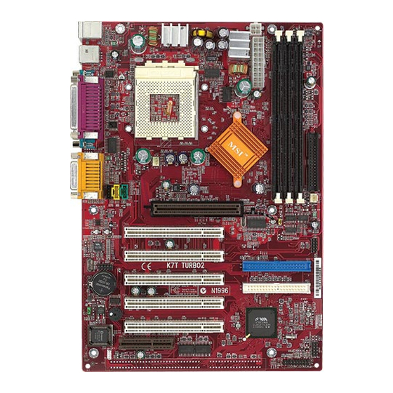
Page 11: Mainboard Layout
Chapter 1 Mainboard Layout Top : mouse JPW1 Bottom: keyboard ports Power Supply SOCKET 462 Top : Parallel Port Bottom: COM A COM B KT133A D-LED (optional) Top : Game port C_FAN1 Bottom: Line-Out Line-In AGP Slot S_FAN1 PCI Slot 1 AC'97 Codec USB2... -
Page 12: Quick Components Guide
Introduction Quick Components Guide Component Function Reference DIMM1~3 Installing DIMM modules See p. 2-5~2-6 Socket 462 Installing CPU See p. 2-2~2-4 C_FAN1 Connecting to CPU FAN See p. 2-20 S_FAN1 Connecting to SYSTEM FAN See p. 2-20 ATX Power Supply Installing power supply See p. -
Page 13: Key Features
Chapter 1 Key Features ATX Form Factor ® CPU: Socket 462 for AMD Duron™/Athlon™/Athlon XP Processors Memory: 3 SDRAM DIMMs Slot: 1 AGP slot, 1 CNR slot, 5 PCI slots, 1 ISA slot (Optional) I/O: 2 serial ports, 1 parallel port, 4 USB 1.1 ports, 1 floppy port, 1 IrDA connector, 1 Audio/Game port Supports Duron processors at 200/266MHz system bus frequencies LAN Wake up Function... -
Page 14: Msi Special Features
Introduction MSI Special Features MSI special features are designed by MSI R&D and only available in MSI mainboards. The K7T Turbo2 mainboard is equipped with PC Alert™ III, Fuzzy Logic™ III, Live BIOS™ and optional D-LED™. PC Alert™ III The PC Alert III is an utility you can find in the CD-ROM disk. - Page 15 Chapter 1 Features: Network Management - Monitoring & remote control Basic System Utilities - Scandisk & Defragment to maintain your HDD 3D Graphics Design - Enables a more friendly user interface Sofware Utilities - SoftCooler Optimized Cooling...
-
Page 16: Fuzzy Logic™ Iii
Introduction Fuzzy Logic™ III The Fuzzy Logic™ III utility allows users to overclock the CPU FSB (Front Side Bus) frequency in the Windows environment. Select the CPU frequency you prefer and click Go to apply the frequency or click Save allowing the system to run at the specified frequency each time when the system is powered on. -
Page 17: D-Led™ & D-Bracket™ (Optional)
Chapter 1 D-LED™ & D-Bracket™ (Optional) The optional D-LED™ uses graphic signal display to help users understand their system. Four LEDs embed- ded in the mainboard provide up to 16 combinations of signals to debug the system. The 4 LEDs can debug all problems that fail the system, such as VGA, RAM or other failures. - Page 18 Introduction D-LED D-Bracket Description Processor Initialization - This will show information regarding the processor (like brand name, system bus, etc…) Testing RTC (Real Time Clock) Initializing Video Interface - This will start detecting CPU clock, checking type of video onboard. Then, detect and initialize the video adapter. BIOS Sign On - This will start showing information about logo, processor brand name, etc….
-
Page 19: Live Bios
After installation, the “MSI Live Update Series” icon (as the right view) will appear on the screen. Double click the “MSI Live Update Series” icon, and the following screen will appear. Four buttons are placed on the left column of the screen. Click the desired button to start the update process. -
Page 20: Chapter 2. Hardware Setup
Hardware Setup Chapter 2. Hardware Setup Hardware Setup This chapter provides you with the information about hardware setup procedures. While doing the installation, be careful in holding the compo- nents and follow the installation procedures. For some components, if you install in the wrong orientation, the components will not work properly. -
Page 21: Central Processing Unit: Cpu
Chapter 2 Central Processing Unit: CPU ® The mainboard supports AMD Athlon™/Athlon XP/Duron™ processors. It uses a CPU socket called Socket A for easy CPU installation. Make sure the CPU has a Heat Sink and a cooling fan attached on the top to prevent overheating. - Page 22 Hardware Setup Thermal Issue for CPU WARNING! As processor technology pushes to faster speeds and higher performance, thermal management becomes increasingly crucial when building computer systems. Maintaining the proper thermal environment is key to reliable operation. As such, the processor must be maintained in the specified thermal requirements.
-
Page 23: Cpu Core Speed Derivation Procedure
Chapter 2 CPU Core Speed Derivation Procedure CPU Clock 100MHz Core/Bus ratio then CPU core speed Host Clock x Core/Bus ratio 100MHz x 7 700MHz CPU Clock Frequency Selection Jumper: J17 The default hardware configuration for CPU Front Side Bus frequency is set at 100MHz. -
Page 24: Memory
Hardware Setup Memory The mainboard provides 3 sockets for 168-pin unbuffered SDRAM DIMM (Double In-Line Memory Module) modules and supports a maximum memory size of 1.5GB. DIMM Slots (DIMM 1~3) Introduction to SDRAM Synchronous DRAM (SDRAM) is a type of dynamic RAM memory chip that has been widely used starting in the latter part of the 1990s. -
Page 25: Dimm Modules Combination
Chapter 2 DIMM Modules Combination At least one DIMM module should be installed on the motherboard. Memory modules can be installed on the slots in any order. The single-/ double-sided memory modules that each DIMM slot supports are listed as below: DIMM 1 DIMM 2... -
Page 26: Power Supply
Hardware Setup Power Supply The mainboard supports ATX power supply for the power system. Before inserting the power supply connector, always make sure that all compo- nents are installed properly to ensure that no damage will be caused. ATX 20-Pin Power Supply This connector allows you to connect to an ATX power supply. -
Page 27: Atx 12V Power Connector: Jpw1
Chapter 2 ATX 12V Power Connector: JPW1 Attach the ATX power supply to the connector and it will supply power to the installed CPU. JPW1 SIGNAL Note: Power current supplied via 12V power connector must exceed 10A.; otherwise, the system could have a stability issue. -
Page 28: Back Panel
Hardware Setup Back Panel The Back Panel provides the following connectors: Mouse Parallel Midi/Joystick Keyboard COM A COM B L-out L-in Mouse Connector ® The mainboard provides a standard PS/2 mouse mini DIN connector ® ® for attaching a PS/2 mouse. -
Page 29: Keyboard Connector
Chapter 2 Keyboard Connector ® The mainboard provides a standard PS/2 keyboard mini DIN connec- ® ® tor for attaching a PS/2 keyboard. You can plug a PS/2 keyboard directly into this connector. Pin Definition SIGNAL DESCRIPTION Keyboard DATA Keyboard DATA No connection Ground Keyboard Clock... -
Page 30: Parallel Port Connector
Hardware Setup Parallel Port Connector The mainboard provides a 25-pin female centronic connector for LPT. A parallel port is a standard printer port that supports Enhanced Parallel Port (EPP) and Extended Capabilities Parallel Port (ECP) mode. Pin Definition SIGNAL DESCRIPTION STROBE Strobe DATA0... -
Page 31: Serial Port Connectors: Com A & Com B
Chapter 2 Serial Port Connectors: COM A & COM B The mainboard has two 9-pin male DIN connectors for serial port COM A and COM B. You can attach a serial mouse or other serial devices. Pin Definition 1 2 3 4 5 SIGNAL DESCRIPTION Data Carry Detect... -
Page 32: Connectors
Hardware Setup Connectors The mainboard provides connectors to connect to FDD, IDE HDD, case, modem, LAN, USB Ports, IR module and CPU/System FAN. Floppy Disk Drive Connector: FDD1 The mainboard provides a standard floppy disk drive connector that supports 360K, 720K, 1.2M, 1.44M and 2.88M floppy disk types. FDD1 2-13... -
Page 33: Hard Disk Connectors: Ide1 & Ide2
Chapter 2 Hard Disk Connectors: IDE1 & IDE2 ® The mainboard uses an IDE controller on the VIA VT82C686B chipset that provides PIO mode 0-4, Bus Master, and Ultra DMA 33/66/100 modes. It has two HDD connectors IDE1 (Primary) and IDE2 (Secondary). You can connect up to four hard disk drives, CD-ROM or 120MB Floppy to IDE1 and IDE2. -
Page 34: Case Connector: Jfp1
Hardware Setup Case Connector: JFP1 The case connector block JFP1 allows you to connect to the Power Switch, Reset Switch, Speaker, Power LED, and HDD LED on the case. B u z z e r (short pin) Speaker R e s e t Switch 1 4 1 5 H D D... - Page 35 Chapter 2 Open pin 14-15: On-board Buzzer Disabled HDD LED HDD LED shows the activity of a hard disk drive connected to the IDE1 or IDE2 connector. Avoid turning the power off while the HDD is working. You can connect the HDD LED from the system case to this pin. 2-16...
-
Page 36: Wake On Lan Connector: Jwol1
Hardware Setup Wake On LAN Connector: JWOL1 This connector allows you to connect to a LAN card with Wake On LAN function. You can wake up the computer via remote control through a local area network. MP_WAKEUP 5VSB JWOL1 Wake On Ring Connector: JMDM1 This connector allows you to connect to a modem card with Wake On Ring function. -
Page 37: Irda Infrared Module Connector: J2
Chapter 2 IrDA Infrared Module Connector: J2 This connector allows you to connect to an IrDA Infrared module. You must configure the setting through the BIOS setup to use the IR function. Signal IRRX IRTX USB Front Panel Connector: USB2 The mainboard provides one Front USB (Universal Serial Bus) pin head- ers that allow you to connect optional USB ports for front panel. -
Page 38: Cd-In/Aux Line-In/Modem-In Connector: Jcd1/Jaux1/J_Phn1
Hardware Setup CD-In/Aux Line-In/Modem-In Connector: JCD1/JAUX1/ J_PHN1 JCD1 connector is for CD-ROM audio connector. JAUX1 connector is for DVD add-on card with Line-in connector. J_PHN1 connector is for modem with internal audio connector. Phone_In Mono_Out JCD1 JAUX1 J_PHN1 Note: Mono_Out is connected to the Modem speaker-out connector. Phone_In is connected to the Modem Microphone-In connector. -
Page 39: Fan Power Connectors: C_Fan1/S_Fan1
Chapter 2 Fan Power Connectors: C_FAN1/S_FAN1 The C_FAN1 (processor fan) and S_FAN1 (system fan) support system cooling fan with +12V. It supports three-pin head connector. When connecting the wire to the connectors, always take note that the red wire is the positive and should be connected to the +12V, the black wire is Ground and should be connected to GND. -
Page 40: D-Bracket™ Connector: J21
Hardware Setup D-Bracket™ Connector: J21 The motherboard comes with J21 connector and you can connect a D- Bracket™ to J21. D-Bracket™ is a USB Bracket integrating four LEDs whose functions are similar to D-LED™ and allows users to identify system problems through 16 various combinations of LED signals. -
Page 41: Jumpers
Chapter 2 Jumpers The motherboard provides the following jumpers for you to set the computer’s function. This section will explain how to change your motherboard’s function through the use of jumpers. Clear CMOS Jumper: JBAT1 There is a CMOS RAM on board that has a power supply from external battery to keep the data of system configuration. -
Page 42: Slots
Hardware Setup Slots The motherboard provides one AGP slot, five 32-bit Master PCI slots, one CNR and one optional ISA slot. AGP Slot PCI Slots CNR Slot ISA Slot (Optional) AGP (Accelerated Graphics Port) Slot The AGP slot allows you to insert the AGP graphics card. AGP is an interface specification designed for the throughput demands of 3D graphics. -
Page 43: Isa Slot (Optional)
Chapter 2 ISA Slot (Optional) The ISA slot allows you to install the ISA expansion card. PCI Interrupt Request Routing The IRQ, abbreviation of interrupt request line and pronounced I-R-Q, are hardware lines over which devices can send interrupt signals to the microprocessor. - Page 44 ® AWARD BIOS Setup C h a p t e r ® AWA R D B I O S Setup ® AWARD BIOS Setup ® The mainboard uses AWARD BIOS ROM that provides a Setup util- ity for users to modify the basic system configuration. The information is stored in a battery-backed CMOS RAM so it retains the Setup information when the power is turned off.
-
Page 45: Entering Setup
Chapter 3 Entering Setup Power on the computer and the system will start POST (Power On Self Test) process. When the message below appears on the screen, press <DEL> key to enter Setup. TO ENTER SETUP BEFORE BOOT, PRESS <CTRL-ALT-ESC> OR <DEL>... -
Page 46: Getting Help
® AWARD BIOS Setup Getting Help After entering the Setup utility, the first screen you see is the Main Menu. Main Menu The main menu displays the setup categories the BIOS supplies. You can use the up/down arrow keys ( to select the item. -
Page 47: The Main Menu
Chapter 3 The Main Menu ® Once you enter AWARD BIOS CMOS Setup Utility, the Main Menu will appear on the screen. The Main Menu displays twelve configurable functions and two exit choices. Use arrow keys to move among the items and press <Enter>... - Page 48 ® AWARD BIOS Setup PnP/PCI Configurations This entry appears if your system supports PnP/PCI. PC Health Status This entry displays the current status of your PC. Frequency/Voltage Control Use this menu to specify your settings for frequency/voltage control. Load Fail-Safe Defaults Use this menu to load the BIOS default values for the minimal/stable per- formance of your PC.
-
Page 49: Standard Cmos Features
Chapter 3 Standard CMOS Features The items inside Standard CMOS Features menu are divided into 13 categories. Each category includes none, one or more setup items. Use the arrow keys to highlight the item you want to modify and use the <PgUp> or <PgDn>... - Page 50 ® AWARD BIOS Setup IDE Primary Master/Primary Slave/Secondary Master/Secondary Slave Press PgUp/<+> or PgDn/<-> to select the hard disk drive type. The specification of hard disk drive will show up on the right hand according to your selection. IDE Primary Master IDE HDD Auto-Detection Press Enter Item Help...
- Page 51 Chapter 3 Halt On The item determines whether the system will stop if an error is detected at boot. Available options are: All Errors The system stops when any error is detected. No Errors The system doesn’t stop for any detected error. All, But Keyboard The system doesn’t stop for a keyboard error.
-
Page 52: Advanced Bios Features
® AWARD BIOS Setup Advanced BIOS Features CMOS Setup Utility - Copyright (C) 1984-2000 Award Software Advanced BIOS Features Anti-Virus Protection Disabled Item Help CPU Internal Cache Enabled External Cache Enabled Menu Level 8 CPU L2 Cache ECC Checking Enabled Quick Power On Self Test Enabled First Boot Device... - Page 53 Chapter 3 CPU Internal Cache/External Cache Cache memory is additional memory that is much faster than conventional DRAM (system memory). When the CPU requests data, the system transfers the requested data from the main DRAM into cache memory, for even faster access by the CPU.
- Page 54 ® AWARD BIOS Setup Swap Floppy Drive Setting to Enabled will swap floppy drives A: and B:. Boot Up Floppy Seek This setting causes the BIOS to search for floppy disk drives at boot time. When enabled, the BIOS will activate the floppy disk drives during the boot process: the drive activity light will come on and the head will move back and forth once.
- Page 55 Chapter 3 Security Option This specifies the type of BIOS password protection that is implemented. Settings are described below: Option Description Setup The password prompt appears only when end users try to run Setup. System A password prompt appears every time when the com- puter is powered on or when end users try to run Setup.
- Page 56 ® AWARD BIOS Setup to shadow (copy) it into the correct area of RAM. Settings: Enabled and Disabled. Full Screen LOGO Show This item enables you to show the company logo on the bootup screen. Settings are: Disabled Shows the POST messages at boot. Enabled Shows a still image (logo) on the full screen at boot.
-
Page 57: Advanced Chipset Features
Chapter 3 Advanced Chipset Features CMOS Setup Utility - Copyright (C) 1984-2000 Award Software Advanced Chipset Features Bank Interleave Enabled Item Help DRAM Timing by SPD SDRAM CAS Latency Auto Menu Level 8 Memory Hole Disabled P2C/C2P Concurrency Enabled Fast R-W Turn Around Disabled System BIOS Cacheable Disabled... - Page 58 ® AWARD BIOS Setup CAS# Latency automatically to be determined by BIOS based on the configurations on the SPD. Selecting No allows users to configure the field manually. SDRAM CAS Latency This controls the timing delay (in clock cycles) before SDRAM starts a read command after receiving it.
- Page 59 Chapter 3 Enabled and Disabled. AGP Aperture Size The item is used to select the size of Accelerated Graphics Port (AGP) aperture. Aperture is a portion of PCI memory address range dedicated for graphics memory address space. Host cycles that hit the aperture range are forwarded to AGP without any translation.
- Page 60 ® AWARD BIOS Setup OnChip Modem Auto allows the mainboard to detect whether a modem is used. If a modem is detected, the onboard modem controller will be enabled; if not, the controller is disabled. Disable the controller if you want to use other controller cards to connect modems.
- Page 61 Chapter 3 AGP Master 1 WS Read When Enabled, one wait state is inserted in the AGP read cycle. Memory Parity/ECC Check Users can set the field to Enabled for memory checking if the type of DRAM installed in your system is Parity or ECC (Error-Correcting Code) DRAM. 3-18...
-
Page 62: Integrated Peripherals
® AWARD BIOS Setup Integrated Peripherals CMOS Setup Utility - Copyright (C) 1984-2000 Award Software Integrated Peripherals OnChip IDE Channel0 Enabled Item Help OnChip IDE Channel1 Enabled IDE Prefetch Mode Enabled Primary Master Auto Menu Level 8 Primary Slave Auto Secondary Master Auto Secondary Slave... - Page 63 Chapter 3 IDE Prefetch Mode The onboard IDE drive interfaces supports prefetching, for faster drive accesses. Set to Disabled if your primary and/or secondary add-in IDE interface does not support prefetching. Primary/Secondary Master/Slave PIO The four items allow you to set a PIO (Programmed Input/Output) mode for each of the four IDE devices that the onboard IDE interface supports.
- Page 64 ® AWARD BIOS Setup UART2 Mode The field allows you to specify the operation mode for serial port “COM B”. Settings are: Standard: RS-232C Serial Port HPSIR : IrDA-compliant Serial Infrared Port ASKIR : Amplitude Shift Keyed Infrared Port IR Function Duplex The field specifies a duplex value for the IR device connected to COM B.
- Page 65 Chapter 3 Onboard Legacy Audio The item enables or disables the onboard audio features of the mainbaord and the following audio options in the BIOS. Sound Blaster The item turns on/off the Sound Blaster feature of the board. If you want to play the Sound Blaster compatible games, you need to set the field to Enabled.
-
Page 66: Power Management Setup
® AWARD BIOS Setup Power Management Setup CMOS Setup Utility - Copyright (C) 1984-2000 Award Software Power Management Setup IPCA function Enabled Item Help Power Management Press Enter ACPI Sleep Type S1(POS) Menu Level 8 PM Control by APM Video Off Option Suspend -->... - Page 67 Chapter 3 Mode. There are three options for power management: Min Saving Minimum Power Management. Doze Mode = 1 Hour, Suspend Mode = 1 Hour, and HDD Power Down = Disable. Max Saving Maximum Power Management. Doze Mode = 1 Min, Suspend Mode = 1 Min, and HDD Power Down = Disable.
- Page 68 ® AWARD BIOS Setup as main memory and wake-capable devices and all system context is saved to main memory. The informa- tion stored in memory will be used to restore the PC to the previous state when an “wake up” event occurs. PM Control by APM Setting to Yes will activate an Advanced Power Management (APM) device to enhance Max Saving mode and stop CPU internal clock.
- Page 69 Chapter 3 Instant-Off The power button functions as a normal power-on/- off button. Delay 4 Sec When you press the power button, the computer enters the suspend/sleep mode, but if the button is pressed for more than four seconds, the computer is turned off.
- Page 70 ® AWARD BIOS Setup VGA, LPT & COM I/O Access, HDD & FDD I/O Access, PCI Master, PowerOn by PCI Card, Wake Up On LAN/Ring, IRQ Wake Up Event These items specify whether the system will be awakened from power saving modes when activity or input signal of the specified hardware peripheral or component is detected.
- Page 71 Chapter 3 IRQ3~IRQ15 Enables or disables the monitoring of the specified IRQ line. If set to Enabled, the activity of the specified IRQ line will prevent the system from entering power saving modes or awaken it from power saving modes. Note: IRQ (Interrupt Request) lines are system resources allocated to I/O devices.
-
Page 72: Pnp/Pci Configurations
® AWARD BIOS Setup PnP/PCI Configurations CMOS Setup Utility - Copyright(C) 1984-2000 Award Software PnP/PCI Configurations PNP OS Installed Item Help Reset Configuration Data Disabled Menu Level 8 Resources Controlled By Auto(ESCD) IRQ Resources Press Enter DMA Resources Press Enter Select Yes if you are using a Plug and Play PCI/VGA Palette Snoop... - Page 73 Chapter 3 98. If you want to configure the system by yourself, select Manaul. IRQ/DMA Resources The items are adjustable only when Resources Controlled By is set to Manual. Press <Enter> and you will enter the sub-menu of the items. IRQ Resources &...
-
Page 74: Pc Health Status
® AWARD BIOS Setup PC Health Status This section is to monitor the current hardware status including CPU temperature, CPU Fan speed, Vcore etc. This is available only if there is hardware monitoring mechanism onboard. CMOS Setup Utility - Copyright(C) 1984-2000 Award Software PC Health Status Shutdown Temperature Disabled... -
Page 75: Frequency/Voltage Control
Chapter 3 Frequency/Voltage Control CMOS Setup Utility - Copyright(C) 1984-2000 Award Software Frequency/Voltage Control CPU Vcore Select Default Item Help Auto Detect DIMM/PCI Clk Enabled Spread Spectrum Modulated Enabled Menu Level 8 Clock By Slight Adjust CPU Clock Ratio Default :Move Enter:Select +/-/PU/PD:Value F10:Save ESC:Exit F1:General Help F5:Previous Values F6:Fail-Safe Defaults... - Page 76 ® AWARD BIOS Setup abled for EMI reduction. Remember to disable Spread Spectrum if you are overclocking because even a 0.25% jitter can introduce a temporary boost in clock speed of 25MHz (with a 1GHz CPU) which may just cause your overclocked processor to lock up.
-
Page 77: Load Fail-Safe/Optimized Defaults
Chapter 3 Load Fail-Safe/Optimized Defaults The two options on the main menu allow users to restore all of the BIOS settings to the default Fail-Safe or Optimized values. The Optimized Defaults are the default values set by the mainboard manufacturer specifically for the optimal performance of the mainboard. - Page 78 ® AWARD BIOS Setup When you select Load Optimized Defaults, a message as below appears: CMOS Setup Utility - Copyright(C) 1984-2000 Award Software 8Frequency/Voltage Control 8Standard CMOS Features 8Advanced BIOS Features Load Fail-Safe Defaults 8Advanced Chipset Features Load Optimized Defaults 8Integrated Peripherals Set Supervisor Password 8Power Management Setup...
-
Page 79: Set Supervisor/User Password
Chapter 3 Set Supervisor/User Password When you select this function, a message as below will appear on the screen: CMOS Setup Utility - Copyright(C) 1984-2000 Award Software 8Frequency/Voltage Control 8Standard CMOS Features 8Advanced BIOS Features Load Fail-Safe Defaults 8Advanced Chipset Features Load Optimized Defaults 8Integrated Peripherals Set Supervisor Password... - Page 80 ® AWARD BIOS Setup use of your computer. The setting to determine when the password prompt is required is the Security Option in the Advanced BIOS Features menu. If the Security Option is set to System, the password is required both at boot and at entry to Setup.
-
Page 81: Save & Exit Setup
Chapter 3 Save & Exit Setup When you want to quit the Setup menu, you can select this option to save the changes and quit. A message as below will appear on the screen: CMOS Setup Utility - Copyright(C) 1984-2000 Award Software 8Frequency/Voltage Control 8Standard CMOS Features 8Advanced BIOS Features... -
Page 82: Exit Without Saving
® AWARD BIOS Setup Exit Without Saving When you want to quit the Setup menu, you can select this option to abandon the changes. A message as below will appear on the screen: CMOS Setup Utility - Copyright(C) 1984-2000 Award Software 8Frequency/Voltage Control 8Standard CMOS Features 8Advanced BIOS Features... -
Page 83: Chapter 4. Installing Drivers
Installing Drivers Chapter 4. Installing Drivers Installing Drivers ® The chapter describes how to install the VIA chipset and AC97 ® audio drivers in different Windows operating systems. When you do the ® ® installation, you should always install VIA chipset driver prior to VIA AC97 audio driver. -
Page 84: Driver Installation For Windows 98Se
Chapter 4 ® Driver Installation for Windows 98SE ® Installing VIA Chipset Driver 1. Insert the supplied CD disk into the CD-ROM drive. 2. The CD will auto-run and the setup screen will appear. 3. Click on Via Chipset Drivers and follow the on-screen instructions to complete the installation. -
Page 85: Driver Installation For Windows 2000
Installing Drivers ® Driver Installation for Windows 2000 Note: Before installation of VIA chipset driver, you should install Win- dows 2000 Service Pack2 or the latest version. ® Installing VIA Chipset Driver 1. Insert the supplied CD disk into the CD-ROM drive. 2. -
Page 86: Driver Installation For Windows Me
Chapter 4 ® Driver Installation for Windows ® Installing VIA Chipset Driver 1. Insert the supplied CD disk into the CD-ROM drive. 2. The CD will auto-run and the setup screen will appear. 3. Click on Via Chipset Drivers follow the on-screen instructions to complete the installation. -
Page 87: Driver Installation For Windows Nt4.0
Installing Drivers ® Driver Installation for Windows NT4.0 ® Note: Install Windows NT4.0 Service Pack 6 or above before install- ® ing the VIA drivers into Windows ® Installing VIA Chipset Driver 1. Insert the provided CD disk into the CD-ROM drive. 2. -
Page 88: Appendix A: Uninstalling Agp Card
Uninstalling AGP Card Appendix A: Uninstalling AGP Card Uninstalling AGP Card The motherboard comes with one AGP retention module installed. The retention module is used to secure the AGP card. This chapter de- scribes how to remove the AGP card from the AGP slot with AGP retention module. -
Page 89: Uninstalling Agp Card
Appendix A Uninstalling AGP Card The motherboard uses the AGP retention module to fasten the installed AGP card. The AGP retention module along with the AGP slot are shown below: Level Retention Module To uninstall the AGP card, follow the instructions: Step 1 –...