Table of Contents
Advertisement
Quick Links
845LDA/845LDAL
USER'S MANUAL
M/B For Socket 478 Pentium 4 Processor
NO. G03-845LDA1A
Release date: May 2002
Trademark:
* Specifications and Information contained in this documentation are furnished for information use only, and are
subject to change at any time without notice, and should not be construed as a commitment by manufacturer.
Advertisement
Table of Contents

Related Manuals for JETWAY 845LDA1A


Summary of Contents for JETWAY 845LDA1A
- Page 1 845LDA/845LDAL USER'S MANUAL M/B For Socket 478 Pentium 4 Processor NO. G03-845LDA1A Release date: May 2002 Trademark: * Specifications and Information contained in this documentation are furnished for information use only, and are subject to change at any time without notice, and should not be construed as a commitment by manufacturer.
-
Page 2: Table Of Contents
TABLE OF CONTENT USER’S NOTICE ................ii MANUAL REVISION INFORMATION ..........1 COOLING SOLUTIONS ..............1 CHAPTER 1 INTRODUCTION OF 845LDA/845LDAL MOTHERBOARD 1-1 FEATURE OF MOTHERBOARD............... 2 1-2 SPECIFICATION ..................3 1-3 PERFORMANCE LIST ................4 1-4 LAYOUT DIAGRAM & JUMPER SETTING ........... 5 CHAPTER 2 HARDWARE INSTALLATION 2-1 HARDWARE INSTALLATION STEPS ............. -
Page 3: User's Notice
3-9 PNP/PCI CONFIGURATION SETUP............32 3-9-1 IRQ RESOURCES ................33 3-10 PC HEALTH STATUS................. 33 3-11 MISCELLANEOUS CONTROL ..............34 3-12 LOAD STANDARD/OPTIMIZED DEFAULTS ........35 3-13 SET SUPERVISOR/USER PASSWORD ........... 35 CHAPTER 4 DRIVER & FREE PROGRAM INSTALLATION MAGIC INSTALL SUPPORTS WINDOWS 95/98/98SE/NT4.0/2000 ..... 36 4-1 INF .... -
Page 4: Manual Revision Information
Manual Revision Information Reversion Revision History Date First Release May 2002 Item Checklist 845LDA/845LDAL Cable for IDE/Floppy CD for motherboard utilities Cable for USB Port 3/4 (Option) □ 845LDA/845LDAL User’s Manual Intel Pentium 4 Processor Family Cooling Solutions As processor technology pushes to faster speeds and higher performance, thermal management becomes increasingly crucial when building computer systems. -
Page 5: Chapter 1 Introduction Of 845Lda/845Ldal Motherboard
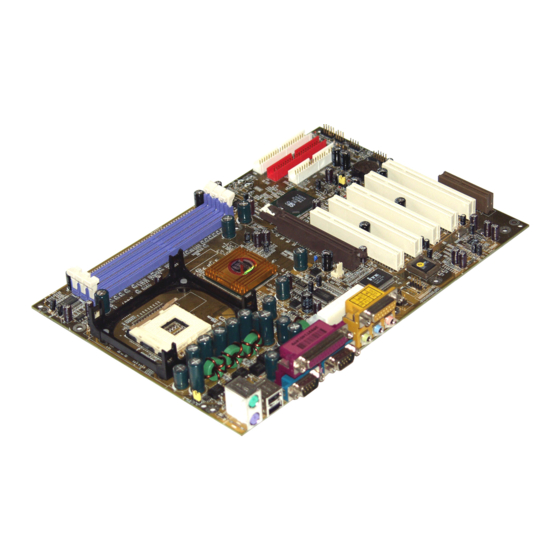
Introduction of 845LDA/845LDAL Motherboard 1-1 Feature of motherboard The 845LDA/845LDAL motherboard is design for use Intel Pentium 4 Processor in 478 Pin Package/Northwood Processor with the Intel 845GL Chipset delivers a high performance and professional desktop platform solution. Which utilize the Socket 478 design and the memory size expandable to 2.0GB. -
Page 6: Performance List
Spec Description ∗ ATX form factor 4 layers PCB size: 30.5x21.0cm Design ∗ Intel 845GL Graphics Memory Controller Hub (GMCH) Chipset Chipset ∗ Intel 82801DB I/O Controller Hub (ICH4) Chipset ∗ Support Intel Pentium 4 478 Pin package utilizes Flip- CPU Socket (mPGA478B Socket) Chip Pin Grid Array (FC-PGA2) package processor... -
Page 7: Layout Diagram & Jumper Setting
The following performance data list is the testing result of some popular benchmark testing programs. These data are just referred by users, and there is no responsibility for different testing data values gotten by users (the different Hardware & Software configuration will result in different benchmark testing results.) Performance Test Report CPU:... - Page 8 PRINT GAME/MIDI PORT (for 845LDAL) PS/2 MOUSE PS/2 Keyboard LINE-IN COM1 LINE-OUT ATX 12V Power Connector K/B Power ON CPU Socket Jumper (JP1) PS2 KB/Mouse Port CPU FAN USB Port ATX P9 Power Conn. /LAN Connector (for 845LDAL) PC99 Back Panel DDR DIMM X2 Intel 845GL Chip SYSFAN2...
-
Page 9: Expansion Sockets
Jumper Name Description Page CPU Frequency Select 3-pin Block CMOS RAM Clear 3-pin Block Keyboard Power On Enable/Disabled 3-pin Block Connectors Connector Name Description Page ATXPWR ATX Power Connector 20-pin Block P.12 ATX12V ATX 12V Power Connector 4-pin Block P.12 ATXP6 ATX P9 Power Connector 6-pin Block... -
Page 10: Chapter 2 Hardware Installation
Hardware installation 2-1 Hardware installation Steps Before using your computer, you had better complete the following steps: 1. Check motherboard jumper setting 2. Install CPU and Fan 3. Install System Memory (DIMM) 4. Install Expansion cards 5. Connect IDE and Floppy cables, Front Panel /Back Panel cable 6. -
Page 11: Install Cpu
2. Forget password 3. After over clocking system boot fail 1-2 closed Normal (Default) 2-3 closed Clear CMOS CMOS RAM Clear Setting (3) Keyboard Power On function Enabled/Disabled: JP1 When setting Enabled you can using keyboard by key in password to power on system. 1-2 closed K/B Power ON Disable 2-3 closed K/B Power ON Enabled... -
Page 12: About Intel Pentium 4 478-Pin Cpu
speakers, MIC, game controllers, and MIDI sound devices. LAN (interface) - Local Area Network - the interface to your local area network. BIOS (Basic Input/Output System) - the program logic used to boot up a computer and establish the relationship between the various components. Driver - software, which defines the characteristics of a device for use by another device or other software. -
Page 13: Expansion Card
This motherboard provides 184-pin DUAL INLINE MEMORY MODULES (DIMM) sites for memory expansion available from minimum memory size of 128MB to maximum memory size of 2.0GB DDR SDRAM. Valid Memory Configurations Bank 184-Pin DIMM Total Memory Bank 0, 1 (DDR1) DDR200/DDR266 128MB∼1.0GB DDR SDRAM Module... -
Page 14: Assigning Irq For Expansion Card
1. Read the documentation for your expansion card and make any necessary hardware or software setting for your expansion card such as jumpers. 2. Remove your computer’s cover and the bracket plate on the slot you intend to use. 3. Align the card’s connectors and press firmly. 4. -
Page 15: Connectors, Headers
IMPORTANT! If using PCI cards on shared slots, make sure that the drivers support “Shared IRQ” or that the cards don’t need IRQ assignments. Conflicts will arise between the two PCI groups that will make the system unstable or cards inoperable. 2-6 Connectors, Headers 2-6-1 Connectors Power Connector (20-pin block) : ATXPWR... - Page 16 This is a new defined 6-pins connector that usually comes with ATX Power Supply. The ATX Power Supply which fully support Pentium 4 processor must including this connector for support extra 3.3V and 5V voltage to maintain system power consumption. Without this connector might cause system unstable because the power supply can not provide sufficient current for system.
- Page 17 COM1 is the 9-pin D-Subminiature mail connector. The On-board serial port can be disabled through BIOS SETUP. Please refer to Chapter 3 “INTEGRATED PERIPHERALS SETUP” section for more detail information. PS/2 MOUSE PRINT GAME/MIDI PORT PS/2 LINE-IN Keyboard COM1 LINE-OUT (11) Floppy drive Connector (34-pin block): FDD This connector supports the provided floppy drive ribbon cable.
-
Page 18: Headers
This connector connects to the next set of Master and Slave hard disks. Follow the same procedure described for the primary IDE connector. You may also configure two hard disks to be both Masters using one ribbon cable on the primary IDE connector and another ribbon cable on the secondary IDE connector. - Page 19 These headers are used for connecting the additional USB port plug. By attaching an option USB cable, your can be provided with two additional USB plugs affixed to the back panel. USB3 USB2 Pin 1 Pin 1 USB Port Headers IDE Activity LED: IDE LED This connector connects to the hard disk activity indicator light on the case.
- Page 20 This connector connects to a LAN card with a WAKE ON-LAN output. This connector power up the system when a wake up signal is received through the LAN card. NOTE: This feature requires that Wake On LAN or Ring In Wake up is enabled. Wake-On-LAN Headers (11) FAN Speed Headers (3-pin) : SYSFAN1, SYSFAN2, CPUFAN These connectors support cooling fans of 350mA (4.2 Watts) or less, depending on the...
- Page 21 (13) CD Audio-In Headers (4-pin) : CDIN CDIN are the connectors for CD-Audio Input signal. Please connect it to CD-ROM CD-Audio output connector. C DIN CD Audio-In Headers...
-
Page 22: Starting Up Your Computer
2-7 Starting Up Your Computer 1. After all connection are made, close your computer case cover. 2. Be sure all the switch are off, and check that the power supply input voltage is set to proper position, usually in-put voltage is 220V∼240V or 110V∼120V depending on your country’s voltage used. -
Page 23: Chapter 3 Introducing Bios
Chapter 3 Introducing BIOS The BIOS is a program located on a Flash Memory on the motherboard. This program is a bridge between motherboard and operating system. When you start the computer, the BIOS program gain control. The BIOS first operates an auto-diagnostic test called POST (power on self test) for all the necessary hardware, it detects the entire hardware device and configures the parameters of the hardware synchronization. -
Page 24: The Main Menu
3-3 The Main Menu Once you enter Award BIOS CMOS Setup Utility, the Main Menu (Figure 3-1) will appear on the screen. The Main Menu allows you to select from fourteen setup functions and two exit choices. Use arrow keys to select among the items and press <Enter> to accept or enter the sub-menu. -
Page 25: Standard Cmos Features
Load Optimized Defaults Use this menu to load the BIOS default values that are settings for optimal performances system operations. Load Standard Defaults Use this menu to load the BIOS default values that are factory settings for the stable performance system operation. Set Supervisor/User Password Use this menu to set User and Supervisor Passwords. -
Page 26: Advanced Bios Features
The time format is <hour><minute><second>. Primary Master/Primary Slave Secondary Master/Secondary Slave Press PgUp/<+> or PgDn/<–> to select Manual, None, Auto type. Note that the specifications of your drive must match with the drive table. The hard disk will not work properly if you enter improper information for this category. - Page 27 Allows you to choose the VIRUS Warning feature for IDE Hard Disk boot sector protection. If this function is enabled and someone attempt to write data into this area, BIOS will show a warning message on screen and alarm beep. Disabled (default) No warning message to appear when anything attempts to access the boot sector or hard disk partition table.
-
Page 28: Advanced Chipset Features
Keystrokes repeat at a rate determined by the keyboard controller. When enabled, the typematic rate and typematic delay can be selected. The settings are: Enabled/Disabled. Typematic Rate (Chars/Sec) Sets the number of times a second to repeat a keystroke when you hold the key down. The settings are: 6, 8, 10, 12, 15, 20, 24, and 30. -
Page 29: Dram Timing Settings
Select Enabled allows caching of the video BIOS, resulting in better system performance. However, if any program writes to this memory area, a system error may result. The settings are: Enabled and Disabled. Memory Hole At 15M-16M You can reserve this area of system memory for ISA adapter ROM. When this area is reserved, it cannot be cached. -
Page 30: Integrated Peripherals
CMOS Setup Utility – Copyright(C) 1984-2002 Award Software Integrated Peripherals > Onboard IDE Function Press Enter Item Help > Onboard Device Function Press Enter > Onboard Super IO Function Press Enter Init Display First PCI Slot Menu Level > Power On Function Button Only KB Power On Password Enter... -
Page 31: Onboard Device Function
The integrated peripheral controller contains an IDE interface with support for two IDE channels. Select Enabled to activate each channel separately. The settings are: Enabled and Disabled. Primary/Secondary Master/Slave PIO The four IDE PIO (Programmed Input/Output) fields let you set a PIO mode (0-4) for each of the four IDE devices that the onboard IDE interface supports. -
Page 32: Onboard Super Io Function
Select Enabled if your system contains a Universal Serial Bus (USB) controller and you have a USB peripherals. The settings are: Enabled, Disabled. USB Keyboard Legacy Support Select Enabled if your system contains a Universal Serial Bus (USB) controller and you have a USB keyboard. -
Page 33: Power Management Setup
To operate the onboard parallel port as Standard Parallel Port only, choose “SPP.” To operate the onboard parallel port in the EPP modes simultaneously, choose “EPP.” By choosing “ECP”, the onboard parallel port will operate in ECP mode only. Choosing “ECP+EPP” will allow the onboard parallel port to support both the ECP and EPP modes simultaneously. -
Page 34: Pm Timer Reload Events
Modem Use IRQ This determines the IRQ in which the MODEM can use. The settings are: 3, 4, 5, 7, 9, 10, 11, NA. Power Button Function Pressing the power button for more than 4 seconds forces the system to enter the Soft-Off state. -
Page 35: Irq Resources
CPU itself uses when communicating with its own special components. This section covers some very technical items and it is strongly recommended that only experienced users should make any changes to the default settings. CMOS Setup Utility – Copyright(C) 1984-2002 Award Software PnP/PCI Configurations Reset Configuration Data Disabled... -
Page 36: Pc Health Status
IRQ-3 assigned to PCI Device Item Help IRQ-4 assigned to PCI Device IRQ-5 assigned to PCI Device IRQ-7 assigned to PCI Device Menu Level >> IRQ-9 assigned to PCI Device IRQ-10 assigned to PCI Device IRQ-11 assigned to PCI Device IRQ-12 assigned to PCI Device... -
Page 37: Load Standard/Optimized Defaults
CMOS Setup Utility – Copyright(C) 1984-2002 Award Software Miscellaneous Control CPU Clock Ratio Item Help Auto Detect PCI Clk Enabled Spread Spectrum Disabled ** Current Host Clock is 100/33MHz ** Menu Level > HOST/PCI Clock at Next Boot is 100/33MHz ** Current DRAM Clock is 133MHz ** DRAM Clock at Next Boot is 133MHz... -
Page 38: Set Supervisor/User Password
When you press <Enter> on this item, you get confirmation dialog box with a message similar Load Standard Defaults (Y/N)? N Pressing <Y> loads the BIOS default values for the most stable, minimal-performance system operations. Load Optimized Defaults When you press <Enter> on this item, you get a confirmation dialog box with a message similar to: Load Optimized Defaults (Y/N)? N Pressing <Y>... -
Page 39: Magic Install Supports Windows 95/98/98Se/Nt4.0/2000
Check your package and there is A MAGIC INSTALL CD included. This CD consists of all DRIVERS you need and some free application programs and utility programs. In addition, this CD also include an auto detect software which can tell you which hardware is installed, and which DRIVERS needed so that your system can function properly. -
Page 40: Iaa
1. Click INF in the MAGIC INSTALL MENU 2. Click NEXT when Chipset Software Install Utility appears 3. This chart shows motherboards supported by 4. Select if you want computer re-started click the driver click Yes Finish NOTE: MAGIC INSTALL will auto detect file path X:\INTEL845\INF\SETUP.EXE This driver supports WINDOWS 98SE/ME/2000/XP (NT4.0 do not require) 4-2 IAA... -
Page 41: Sound Install Alc101 Audio Codec Driver
1. Click VGA when MAGIC INSTALL MENU Click NEXT When Intel (R) Brookdale-G- appears 830M Chipset Graphics Driver Software Setup Click YES, This is Announce CopyRight 4. If You Want Re-start Computer , Click FINISH 4-4 SOUND Install ALC101 Audio Codec Driver 1. - Page 42 3. Click Finish and Restart Windows 4. Click Start→Program→Avance Sound Manager→AvRack. Then AVRACK Windows appears 5. Avance Audio Rack table can play CD, 6. Sound Effect select and KaraOK Mode WAV, MID, MP3, AVI, MPG Format File Function 7. Manual Sound Effect Setting NOTE: MAGIC INSTALL will auto detect file path: X:\CODEC\ALCCODEC\SETUP.EXE (for WINDOWS 98SE/ME/NT4.0/2000/XP)
-
Page 43: Lan Install Rtl8100 Lan Controller Driver
4-5 LAN Install RTL8100 LAN Controller Driver (Only for 845LDAL) The path of the file: for WINDOWS 98SE is X:\RTLLAN\WIN98 for WINDOWS 98ME is X:\RTLLAN\WIN98ME for WINDOWS NT4.0 is X:\RTLLAN\WINNT4 for WINDOWS 2000 is X:\RTLLAN\WIN2000 WINDOWS 98SE/98ME/2000/XP Setup 1. Click LAN when Magic Install Menu appears 2. Click NEXT when Realtak PCI LAN Driver Setup appears 3. -
Page 44: Pc-Health Intel 845 Pc-Health Monitor
4-6 PC-HEALTH Intel 845 PC-Health Monitor The path of the file is X:\INTEL845\HW30\SETUP.EXE (Only support WINDOWS 98SE/ME) In Windows 98 Winbond Hardware Doctor Monitoring Software needs some system files to copy in Utility that’s why it needs install PC-HEALTH twice to complete setup. 1. -
Page 45: Magic Bios Install Bios Live Update Utility
3. This is a CPU/System Fan Speed and 4. This is a CPU and System Memory status Temperature status information information 4-7 MAGIC BIOS Install BIOS Live Update Utility 1. Click Magic BIOS when Magic Install 2. Click Next to install the Magic BIOS in MENU appears Destination Folder 3. -
Page 46: Pc-Cillin Install Pc-Cillin2002 Anti-Virus Program
Click Yes if you want to update the BIOS When System programming BIOS don’t turn otherwise choose No to exit off power, after finish update BIOS, the system will clear CMOS and automatically Restart When choose From Local Driver to update 10. -
Page 47: How To Install Usb 2.0 Driver
3. This is license agrement, select "I Accept the 4. Click NEXT and Enter your Customer terms" and Click NEXT Information, Click NEXT or choose Change to change the path for the file to be stored 5. Click INSTALL, Start to install the software 6. Setup Complete and click FINISH 7. -
Page 48: How To Disable On-Board Sound
How to install USB 2.0 driver : Step1: First make sure you have two files, one is support from Intel hardware driver which in CD the path is X:\INTEL845\USB2|USB2.INF, and the other one is support form Microsoft Windows OS file name is USBHUB.SYS. Step2: Boot from Windows 2000/XP Double click “My computer”...