Summary of Contents for Delta 50-665
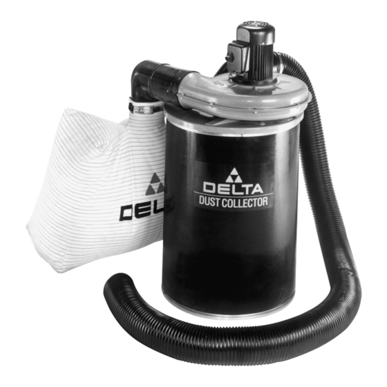
- Page 1 H.P. Dust Collector (Model 50-665) Shown with Accessory Dust Collector Drum D ATED 8-8-99 PA RT NO. 1342493 'Delta International Machinery Corp. 1999...
-
Page 2: Table Of Contents
TABLE OF CONTENTS SAFETY RULES ..........................3 IMPORTA N T SAFETY RULES F O R D U S T COLLECTO R S. -
Page 3: Safety Rules
IMPORTANT SAFETY RULES W oodworking can be dangerous if safe and proper operating procedures are not followed. As with all machinery, t h e r e a r e c e r ta i n hazards involved with the operation of the product. Using the machine with respect and caution will considerably lessen the possi- b i l i t y o f p e r s o n a l i n j u r y. -
Page 4: Importa N T Safety Rules F O R D U S T Collecto R S
2 . D O N O T leave the dust collector plugged into the e l e c t r i c a l o u t l e t . Unplug dust collector from the outlet when not in use and before servicing, changing bags, unclogging and cleaning. -
Page 5: U N Packing
Carefully unpack the dust collector from the shipping container and check for any damaged or missing pa r ts. Fig. 2, illustrates the components of the dust collector. 1 . Blower and Motor Assembly 2 . Vacuum Hose 3 . Cylinder 4 . -
Page 6: A S S E M B Ly
3 . Peel the adhesive paper (E) Fig. 5, from the back of the gasket material (F) and press the gasket material around the underside of the dust collector cover (C). Cut o ff any excess gasket material. 4 . Carefully turn the assembly over. Place gasket (G) Fig. - Page 7 5 . Position the remaining inlet elbow (K) F i g . 8 , a t t h e underside of dust collector lid (C) as shown. Align the mounting holes in inlet elbows (K) Fig. 8, with screws (J) assembled to upper inlet elbow (H) shown in Fig.
- Page 8 8 . Place the entire blower and motor assembly (C) Fig. 13, into collection drum (R) (not supplied). W ARNING: The dust collector has a safety guard (P) Fig. 14, at the blower housing of the dust collector, which contains a high speed radial blade that can amputate fingers, grab loose clothing and neckties, or propel dust at high velocities.
- Page 9 1 0 . Insert the bag clamp (Z) Fig. 16, through the loops o f the dust bag (A). 11 . Clamp dust bag (A) Fig. 17, to bag elbow (V) as shown by fastening bag clamp (Z). 1 2 . Assemble reducer (B) Fig. 18, over the end of inlet elbow (H).
-
Page 10: Connecting D U S T Collecto R To P O W E R S O U R C E
CONNECTING DUST COLLECTOR TO Before connecting your dust collector to an electrical power system, be sure the motor rating agrees with the electrical system it is to be connected to. SINGLE P H A S E O P E R ATION... -
Page 11: Locking Switch In The Off Position
LOCKING SWITCH IN THE OFF POSITION W e suggest when the dust collector is not in use that the ON/OFF switch be locked in the OFF position. This can be done by grasping the switch toggle (B) Fig. 23, and pulling it out of the switch (A) as shown. W ith the switch toggle (B) removed, the switch will not operate. -
Page 12: W A R R A N T Y
Delta Building Trades and Home Shop Machinery Two Year Limited Warranty Delta will repair or replace, at its expense and at its option, any Delta machine, machine pa r t , or machine accessory which in normal use has proven to be defective in workmanship or material, provided that the customer returns the product prepaid to a Delta factory service center or authorized service station with proof of purchase of the product within two years and provides Delta with reasonable opportunity to verify the alleged defect by inspection.


