Pioneer PD-F1007 Service Manual
File-type cd player
Hide thumbs
Also See for PD-F1007:
- Service manual (57 pages) ,
- Operating instructions manual (43 pages) ,
- Service manual (8 pages)
Table of Contents
Advertisement
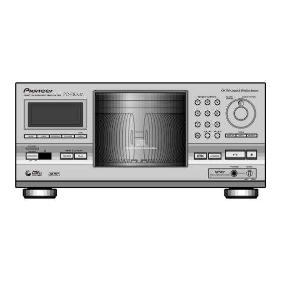
FILE-TYPE CD PLAYER
PD-F1007
THIS MANUAL IS APPLICABLE TO THE FOLLOWING MODEL(S) AND TYPE(S).
Model
Type
PD-F1007
KU
CONTENTS
1. SAFETY INFORMATION .................................... 2
2. EXPLODED VIEWS AND PARTS LIST ............. 3
3. SCHEMATIC DIAGRAM ................................... 10
4. PCB CONNECTION DIAGRAM ....................... 22
5. PCB PARTS LIST ............................................. 30
6. ADJUSTMENT .................................................. 34
PIONEER ELECTRONIC CORPORATION
PIONEER ELECTRONICS SERVICE, INC. P.O. Box 1760, Long Beach, CA 90801-1760, U.S.A.
PIONEER ELECTRONIC (EUROPE) N.V. Haven 1087, Keetberglaan 1, 9120 Melsele, Belgium
PIONEER ELECTRONICS ASIACENTRE PTE. LTD. 501 Orchard Road, #10-00 Wheelock Place, Singapore 238880
PIONEER ELECTRONIC CORPORATION 1998
Power Requirement
AC120V
4-1, Meguro 1-Chome, Meguro-ku, Tokyo 153-8654, Japan
7. GENERAL INFORMATION .............................. 44
7.1 PARTS ....................................................... 44
7.1.1 IC ....................................................... 44
7.1.2 DISPLAY ........................................... 47
7.2 DIAGNOSIS ................................................ 48
7.2.1 DISASSEMBLY ................................. 48
7.2.2 ERROR CCHECK DISPLAY ............. 51
7.2.3 EXPLANATION OF DISC
DETECTION ...................................... 52
7.3 BLOCK DIAGRAM ...................................... 54
8. PANEL FACILITIES AND SPECIFICATIONS
....................................................... 55
T–DZE AUG. 1998 Printed in Japan
ORDER NO.
RRV2001
Remarks
Advertisement
Table of Contents

Related Manuals for Pioneer PD-F1007


Summary of Contents for Pioneer PD-F1007
- Page 1 PIONEER ELECTRONICS SERVICE, INC. P.O. Box 1760, Long Beach, CA 90801-1760, U.S.A. PIONEER ELECTRONIC (EUROPE) N.V. Haven 1087, Keetberglaan 1, 9120 Melsele, Belgium PIONEER ELECTRONICS ASIACENTRE PTE. LTD. 501 Orchard Road, #10-00 Wheelock Place, Singapore 238880 PIONEER ELECTRONIC CORPORATION 1998...
-
Page 2: Safety Information
For the latest information, always consult the current Also test with plug reversed PIONEER Service Manual. A subscription to, or ad- (Using AC adapter ditional copies of, PIONEER Service Manual may be plug as required) obtained at a nominal charge from PIONEER. -
Page 3: Exploded Views And Parts List
PD-F1007 2. EXPLODED VIEWS AND PARTS LIST NOTES : Parts marked by “ NSP ” are generally unavailable because they are not in our Master Spare Parts List. mark found on some component parts indicates the importance of the safety factor of the part. - Page 4 PD-F1007 2.2 EXTERIOR (1/2) (1/2) Refer to " 2.3 EXTERIOR (2/2)". 11 (1/2) (2/2) 11 (2/2) Hood Base Assy Refer to " 2.5 FRONT PANEL ASSY SECTION".
- Page 5 PD-F1007 Hood Base Assy Section No. 14: Center Pole 14 (2/2) 14 (1/2) No. 11: Trans Cover 11(1/2) 11(2/2) EXTERIOR (1/2) PARTS LIST Mark No. Description Part No. Mark No. Description Part No. MAIN BOARD ASSY PWZ3822 Hood Base Assy Section...
- Page 6 PD-F1007 2.3 EXTERIOR (2/2) Refer to " 2.4 FLOAT BASE ASSY SECTION".
- Page 7 PD-F1007 EXTERIOR (2/2) PARTS LIST Mark No. Description Part No. SENSOR BOARD ASSY PWZ3781 SELECT BOARD ASSY PWZ3785 LOADING BOARD ASSY PWZ3788 LOADING SW BOARD ASSY PWZ3790 RADIATE BOARD ASSY PWZ3791 RECEIVE BOARD ASSY PWZ3792 VOLUME BOARD ASSY PWZ3866 Clamp Spring...
- Page 8 PD-F1007 2.4 FLOAT BASE ASSY SECTION FLOAT BASE ASSY SECTION PARTS LIST Mark No. Description Part No. Gear 1 PNW2052 Gear 2 PNW2053 Gear 3 PNW2054 Carriage Base PNW2699 Pickup Assy - S PEA1335 D.C. Motor Assy (SPINDLE) PEA1235 Carriage DC Motor Assy...
-
Page 9: Front Panel Assy Section
PD-F1007 2.5 FRONT PANEL ASSY SECTION FRONT PANEL ASSY SECTION PARTS LIST Mark No. Description Part No. Mark No. Description Part No. DISPLAY BOARD ASSY PWZ3839 Enter Spring PBH1228 FUNCTION BOARD ASY PWZ3847 Jog Sheet PEC1042 HEADPHONE BOARD ASSY PWZ3860... -
Page 10: Schematic Diagram
PD-F1007 3. SCHEMATIC DIAGRAM Note : When ordering service parts, be sure to refer to "EXPLODED VIEWS and PARTS LIST" or "PCB PARTS LIST". 3.1 MECHANISM BOARD, DOOR MOTOR BOARD, DOOR SW BOARD, LED BOARD and PICKUP Large size ASSEMBLIES... - Page 11 PD-F1007 3.2 LOADING SW, LOADING BOARD, SENSOR BOARD, RECIEVE BOARD, RADIATE BOARD and SELECT BOARD ASSEMBLIES LOADING BOARD ASSY (PWZ3788) LOADING SW ASSY (PWZ3790) CN203 REAF SW VSK1011 LOADING MOTOR VXM1033 SENSOR BOARD ASSY VOLUME BOARD ASSY (PWZ3781) 1.5k (PWZ3866)
-
Page 12: Main Board Assy
PD-F1007 3.3 MAIN BOARD ASSY CAUTION : FOR CONTINUED PROTECTION AGAINST RISK OF FIRE, REPLACE ONLY WITH SAME TYPE NO. ICP-N10, MFD BY ROHM CO., FOR IC35 AND IC36. MAIN 2 23 BOARD ASSY (PWZ3822) 1.8V -0.7V 1.8V 1.6V CN610 1.6V... - Page 13 PD-F1007 IC301(CXD2529Q) :PLAY MODE 3 - 4 PIN No. Voltage(V) 1.2-1.3 1.2-1.4 0.05 PIN No. 50-55 Voltage(V) 2.6-2.7 PIN No. 84-86 89-90 91-92 93-95 Voltage(V) J501...
- Page 14 PD-F1007 (SEL) ASSY PICUP...
- Page 15 PD-F1007 (SEL)
- Page 16 PD-F1007...
- Page 17 PD-F1007...
- Page 18 PD-F1007 Waveforms 1 50T-JUMP: After switching to the pause mode, press the manual search key. Note: The encircled numbers denote measuring point in the schematic diagram. 2 FOCUS-IN: Press the play key without loading a disc. IC202-Pin 4: 50T - JUMP (*1) MODE...
- Page 19 PD-F1007 IC202-Pin 9: TRACK SEARCH MODE IC301-Pin 54 : PLAY MODE (1kHz) (CADR) (BCK) 2V/div 200msec/div 2V/div 500nsec/div – GND – GND IC301-Pin 50 : PLAY MODE (1kHz) IC301-Pin 27 : PLAY MODE (MDP) (LRCK) 2V/div 2 sec/div 2V/div 10 sec/div –...
-
Page 20: Display Board Assy
PD-F1007 3.4 DISPLAY BOARD, FUNCTION BOARD, HEADPHONE BOARD and POWER BOARD ASSEMBLIES DISPLAY BOARD ASSY S701 : MODE S702 : CLEAR S703 : PROGRAM S704 : RANDOM CN351 S705 : TIME/CHARA S706 : POWER DISPLAY BOARD ASSY S707 : SINGLE LOADER ACCESS... -
Page 21: Power Board Assy
PD-F1007 POWER BOARD ASSY (PWZ3852) CN11 LIVE HEADPHONE BOARD ASSY (PWZ3860) CN401 FUNCTION BOARD ASSY (PWZ3847) FUNCTION BOARD ASSY S751–S760 : DIRECT CUSTOM (1–10) S761 : Track/Manual search (reverse direction) S762 : Track/Manual search (forward direction) S763 : TITLE/DISPLAY S764 : TITLE/SEARCH... -
Page 22: Pcb Connection Diagram
PD-F1007 4. PCB CONNECTION DIAGRAM 4.1 MECHANISM BOARD, DOOR MOTOR BOARD, DOOR SW BOARD and LED BOARD ASSEMBLIES SIDE A NOTE FOR PCB DIAGRAMS: MECHANISM BOARD ASSY 1. Part numbers in PCB diagrams match those in the schematic diagrams. CARRIAGE 2. - Page 23 PD-F1007 4.2 LOADING SW, LOADING BOARD, SENSOR BOARD, RECIEVE BOARD, RADIATE BOARD, SELECT BOARD and VOLUME BOARD ASSEMBLIES SIDE A LOADING BOARD ASSY LOADING SW ASSY CN203 (PNP1452-B) (PNP1452-B) RADIATE BOARD ASSY VOLUME BOARD ASSY (PNP1452-B) SENSOR BOARD ASSY RECIEVE...
- Page 24 PD-F1007 4.3 MAIN BOARD ASSY SIDE A MAIN BOARD ASSY IC23 IC35 IC31 IC202 IC21 IC25 Q351 IC36 IC32 IC201 IC203 IC34 Q391 Q151 VR152 VR153 VR156 VR151 VR155 VR154 CN701 CN610 To PICKUP ASSY J601...
- Page 25 PD-F1007 SIDE A Q404 Q151 Q414 Q413 Q424 Q403 Q423 VR153 HEADPHONE BOARD ASSY (PNP1451-C) (PNP1450-A) J1601 J631 J651...
- Page 26 PD-F1007 MAIN BOARD ASSY IC406 IC408 IC407 SIDE B Q470 IC405 Q471 IC401 Q426 Q451 IC341 Q425 Q405 Q415 IC301 Q152 (PNP1450-A)
- Page 27 PD-F1007 SIDE B Q382 Q363 Q381 IC352 IC301 Q152 IC331 IC151 Q406 Q416 Q362 IC351...
- Page 28 PD-F1007 4.4 DISPLAY BOARD and FUNCTION BOARD ASSEMBLIES SIDE A DISPLAY BOARD ASSY CN351 (PNP1451-C) FUNCTION BOARD ASSY (PNP1451-C)
- Page 29 PD-F1007 4.5 POWER BOARD ASSY SIDE A POWER BOARD ASSY CN11 LIVE NEUTRAL (PNP1451-C)
-
Page 30: Pcb Parts List
PD-F1007 5. PCB PARTS LIST NOTES: Parts marked by "NSP" are generally unavailable because they are not in our Master Spare Parts List. mark found on some component parts indicates the importance of the safety factor of the part. Therefore, when replacing, be sure to use parts of identical designation. - Page 31 PD-F1007 Mark No. Description Part No. Mark No. Description Part No. CEAT101M35 RECIEVE BOARD ASSY CEAT101M50 C433, C434, C439, C440 CEAT220M25 SEMICONDUCTORS C131–C133, C211, C212 CEAT330M16 Q621 PT381FBC C169, C170 CEAT4R7M50 CEATR22M50 OTHERS C309 CEATR47M50 CABLE HOLDER 51048-0300 C954 CFTLA104J50...
- Page 32 PD-F1007 Mark No. Description Part No. Mark No. Description Part No. JA391, JA392, JA951, JA952 JACK RKN1004 POWER BOARD ASSY CN201 CONNECTOR 6P RKP-533 CN202 CONNECTOR SLW16S-1C7 SEMICONDUCTORS PCB BINDER VEF1040 IC61 NJM78M56FA SCREW PLATE VNE1948 DTC124ES 1SS254 X351 CERAMIC RES.(4.19MHz) VSS1028...
- Page 33 PD-F1007 Mark No. Description Part No. DOOR SW BOARD ASSY OTHERS CABLE HOLDER 51048-0300 J632 3P JUMPER WIRE D20PDD0315E REAF SWITCH VSK1011 VOLUME BOARD ASSY RESISTORS VR601 (22k ) VCP1158 OTHERS CN604, CN605 3P JUMPER CONNECTOR 52147-0310 KN601 JUMPER TERMINAL...
-
Page 34: Spindle Motor
PD-F1007 6. ADJUSTMENT 6.1 PREPARATIONS 6.1.1 Jigs and Measuring Instruments 8 cm DISC CD TEST DISC screwdriver screwdriver screwdriver (With at last about 20 (YEDS-7) (small) (medium) (large) minutes recording) Dual-trace Precise Ball point hexagon wrench Low-frequency oscilloscope Digital multi meter screwdriver (size: 1.5mm) - Page 35 PD-F1007 6.2 ADJUSTMENT 6.2.1 How to Start/Cancel Test Mode TEST MODE : ON POWER Short Point Short Point Power Switch : ON MAIN BOARD ASSY MAIN BOARD ASSY TEST MODE : PLAY TEST DISC : YEDS-7 MODE CLOSE OPEN inwards...
- Page 36 PD-F1007 6.2.3 Check and Adjustment 1. Disc-detect Circuit Adjustment MAIN BOARD ASSY (Peak hold circuit) INPUT OUTPUT Digital multi meter (Under Base) VR601 TP601 VOLUME BOARD ASSY Photocell for detection Peak hold voltage (mV) Revised voltage (mV) to 840 840 to 860...
- Page 37 PD-F1007 Step 15: Do steps 6-10 again. In step 10, the number that Step 1: Connect all equipment as shown in the diagram. appears on the Digital Multi Meter should be Step 2: Turn on the power of the CD player. Put the test between 900-1150 mV.
- Page 38 PD-F1007 2. Focus Offset Adjustment Test mode DC voltage VR154 0 50mV None disc MAIN BOARD ASSY Oscilloscope DC Mode V: 5mV/div H: 10mSec/div Player START (CN201) Prove (10:1) MAIN BOARD ASSY 3. Grating Adjustment Turn counterclockwise from null. Locate null.
- Page 39 PD-F1007 4. Tracking Error Barance Adjustment Test mode SPDL servo CLOSE FOCUS servo CLOSE TRKG servo OPEN Innermost TEST DISC circumference VR155 (1 TRK) PLAY MAIN BOARD ASSY Oscilloscope DC Mode V: 10mV/div Player START H: 5mSec/div Low pass filter 1...
- Page 40 PD-F1007 6. RF Level Adjustment Test mode SPDL servo CLOSE FOCUS servo CLOSE 1.2VP-P TRKG servo CLOSE 0.1V Innermost TEST DISC circumference VR153 (1 TRK) PLAY MAIN BOARD ASSY Oscilloscope AC Mode V: 50mV/div H: 10mSec/div Player START (CN201) Prove (10:1) MAIN BOARD ASSY 7.
- Page 41 PD-F1007 8. RF Level Adjustment Check Test mode CLOSE SPDL servo FOCUS servo CLOSE TRKG servo CLOSE 1.2VP-P 0.1V Innermost TEST DISC circumference VR153 (1 TRK) PLAY MAIN BOARD ASSY Make adjustment if the value exceeds the specified range. Oscilloscope...
- Page 42 PD-F1007 10. Focus Best Adjustment Test mode SPDL servo CLOSE FOCUS servo CLOSE TRKG servo CLOSE Innermost TEST DISC circumference VR156 (1 TRK) Adjust the RF level to maximum, with PLAY MAIN BOARD ASSY the focus error voltage within 150mV.
- Page 43 PD-F1007 12. Focus Best Adjustment Adjust this point only if adjustment was made in item 10. Test mode SPDL servo CLOSE FOCUS servo CLOSE TRKG servo CLOSE Innermost TEST DISC circumference VR156 (1 TRK) Adjust the RF level to maximum, with...
-
Page 44: General Information
PD-F1007 7. GENERAL INFORMATION ¶ The information shown in the list is basic information and may not 7.1 PARTS correspond exactly to that shown in the schematic diagrams. 7.1.1 IC PD4997A (IC701: DISPLAY BOARD ASSY) Display Control Micro-computer Pin Function No. - Page 45 PD-F1007 PD4996A (IC351: MAIN BOARD ASSY) System Control Micro-computer Pin Function No. Symbol Name I/O Description No. Symbol Name I/O Description P16/ANI6 SYNC1 Synchronization input 1 P120/RTP0 DLAT DAC control data, latch pulse output (pull-up required) 2 P121/RTP1 XLAT LSI control data, latch pulse output...
- Page 46 PD-F1007 No. Symbol Name I/O Description No. Symbol Name I/O Description – P31/TO1 Output for loading motor (LIN: H, LOUT: L) P56/A14 P32/TO2 LOUT OUT (LIN: L, LOUT: H) External RAM data Input/Output Stop (LIN: L, LOUT: L) P57/A15 P33/TI1...
-
Page 47: Display
PD-F1007 7.1.2 DISPLAY PEL1096 (V701: DISPLAY BOARD ASSY) Vacuum Fluorescent Display Pin Assignment Pin Connection PIN NO. CONNECTION PIN NO. CONNECTION PIN NO. 0 9 8 7 6 5 4 3 2 1 CONNECTION Note 1) F1, F2 ..Filament 5) DL .... -
Page 48: Diagnosis
PD-F1007 7.2 DIAGNOSIS 7.2.1 DISASSEMBLY Removal of the Servo Mechanism Assy GM 1 Remove the Bonnet. (Left and right Screw A side: 2, rear side: 3) MAIN BOARD ASSY 2 Remove the wires from the MAIN BOARD Assy. (9 places) - Page 49 PD-F1007 6 Remove the screws E (4 screws), and then remove the Disc Guard. 7 Remove the Float Base Assy and Clamp Holder. Float Base Assy Disc Guard Screw E ( 4) Clamp Holder Clamp Support Clamp Spring Front Front...
- Page 50 PD-F1007 Removal of the Gear Holder Assy and the Disc Rack Screw A ( 2) 1 Perform the steps 1 to 6 of " Removal of the Servo Mechanism Gear Holder Assy Assy GM ". 2 Remove the screws A (2 screws), and then remove the Gear Holder Assy.
- Page 51 PD-F1007 7.2.2 ERROR CHECK DISPLAY Error check mode (display of the error history for the last 16 times) Seconds digits is entered when the "TIME/CHARA" button is pressed in test mode. By looking at this display, it can be seen in which status the...
-
Page 52: Explanation Of Disc Detection
PD-F1007 7.2.3 EXPLANATION OF DISC DETECTION 1. Detection of the rack position <<< Rack section >>> There are two types of slits on the rear of the rack, and their User Display Contents combination is used to find which disc has been selected during Display rack rotation. - Page 53 PD-F1007 3. Disc Detection Method Disc No. 217 218 219 220 221 222 223 224 225 226 227 228 229 230 231 232 233 234 3-1 In Regard to the Disc Detection Method DCNT DPOS Disc detection is performed after stabilization of the rotation speed after rack rotation start and completion of acceleration.
-
Page 54: Block Diagram
PD-F1007 7.3 BLOCK DIAGRAM SLAVE Buffer AUDIO IN DECODER SERVO IC407, IC408 PICKUP + DAC CONTROLLER AUDIO IC405 NJM4558D-D Assembly IC301 IC151 SIGNAL NJM4558D-D CXD2519Q CXA1782CQ H.P. Buffer IC406 M5218AFP Focus Tracking TEXT ENCODER IC302 LC89170M IC351 PD4996A IC201 DISPLAY CONTROL... -
Page 55: Panel Facilities And Specifications
PD-F1007 8. PANEL FACILITIES AND SPECIFICATIONS PANEL FACILITIES DIRECT CUSTOM RANDOM button buttons FRONT PANEL TIME/CHARA Jog dial button ENTER Hood PROGRAM button TITLE/INPUT button CLEAR button TITLE/SEARCH button MODE button TITLE/DISPLAY button STANDBY Stop button (7) indicator Play/Pause button... -
Page 56: Specifications
PD-F1007 SPECIFICATIONS 1. General 4. INPUT Output terminal Type ........... Compact disc digital audio system Audio line output Power requirements ..........AC 120V, 60 Hz Control input/output jacks Power consumption ..............15W CD-DECK SYNCHRO jack Power consumption in standby mode ........2W Optical digital output jack Operating temperature ..........