Pioneer PD-F1009 Service Manual
Hide thumbs
Also See for PD-F1009:
- Operating instructions manual (20 pages) ,
- Operating instructions manual (124 pages) ,
- Operating instructions manual (20 pages)
Table of Contents
Advertisement
QQ
3 7 63 1515 0
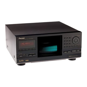
FILE-TYPE COMPACT DISC PLAYER
PD-F1009
THIS MANUAL IS APPLICABLE TO THE FOLLOWING MODEL(S) AND TYPE(S).
Model
Type
PD-F1009
TE
L 13942296513
KU/CA
MY
CONTENTS
1. SAFETY INFORMATION .................................... 2
2. EXPLODED VIEWS AND PARTS LIST ............. 4
3. BLOCK DIAGRM AND SCHEMATIC DIAGRAM ... 14
4. PCB CONNECTION DIAGRAM ....................... 22
5. PCB PARTS LIST ............................................. 38
6. ADJUSTMENT .................................................. 44
7. GENERAL INFORMATION .............................. 48
www
7.1 DIAGNOSIS ................................................ 48
7.1.1 DISASSEMBL .................................... 48
.
PIONEER CORPORATION
PIONEER ELECTRONICS SERVICE, INC. P.O. Box 1760, Long Beach, CA 90801-1760, U.S.A.
PIONEER EUROPE N.V. Haven 1087, Keetberglaan 1, 9120 Melsele, Belgium
PIONEER ELECTRONICS ASIACENTRE PTE. LTD. 253 Alexandra Road, #04-01, Singapore 159936
PIONEER CORPORATION 2000
http://www.xiaoyu163.com
Power Requirement
AC120V
AC220-230V
x
ao
u163
y
i
4-1, Meguro 1-chome, Meguro-ku, Tokyo 153-8654, Japan
http://www.xiaoyu163.com
2 9
8
◊Û¿X,??/
FILE–TYPE COMPACT DISC PLAYER
1
DISC
TRACK
MIN
SEC
4
7
DISC
MODE
CLEAR
PROGRAM
REPEAT
DISPLAY
STANDBY
FILE–TYPE CD MECHANISM
Î
SINGLE LOADER
STANDBY/ON
ACCESS
PLAY
OPEN/
CLOSE
CDF
ILE
CD TEXT
Q Q
3
6 7
1 3
1 5
7.1.2 ERROR CHECK DISPLAY ................... 51
7.1.3 EXPLANATION OF DISC DEECTION .. 54
7.1.4 OPERATION FLOWCHART ................ 54
7.2 PARTS ....................................................... 55
7.2.1 IC ....................................................... 55
7.2.2 DISPLAY ........................................... 58
8. PANEL FACILITIES AND SPECIFICATIONS
co
.
9 4
2 8
DISC
PUSH ENTER
2
3
5
6
8
9
0
TRACK
4 1 ¡ ¢
RANDOM
6
7
UNLOAD
ORDER NO.
1-BIT DLC
DIRECT LINEAR CONVERSION
RRV2262
Remarks
0 5
8
2 9
9 4
2 8
m
....................................................... 59
T–ZZR JAN. 2000 Printed in Japan
9 9
9 9
Advertisement
Table of Contents

Related Manuals for Pioneer PD-F1009


Summary of Contents for Pioneer PD-F1009
-
Page 1: Te L 13942296513
PIONEER CORPORATION 4-1, Meguro 1-chome, Meguro-ku, Tokyo 153-8654, Japan PIONEER ELECTRONICS SERVICE, INC. P.O. Box 1760, Long Beach, CA 90801-1760, U.S.A. PIONEER EUROPE N.V. Haven 1087, Keetberglaan 1, 9120 Melsele, Belgium PIONEER ELECTRONICS ASIACENTRE PTE. LTD. 253 Alexandra Road, #04-01, Singapore 159936 PIONEER CORPORATION 2000 T–ZZR JAN. -
Page 2: Safety Information
The use of a substitute replacement component which does Leakage 0.5mA current Device not have the same safety characteristics as the PIONEER tester under recommended replacement one, shown in the parts list in test this Service Manual, may create shock, fire, or other hazards. -
Page 3: Pd-F1009
PD-F1009 3 7 63 1515 0 IMPORTANT LASER DIODE CHARACTERISTICS THIS PIONEER APPARATUS CONTAINS MAXIMUM OUTPUT POWER: 7 mW LASER OF CLASS 1. WAVELENGTH: 780 – 785 nm SERVICING OPERATION OF THE APPARATUS S H O U L D B E D O N E B Y A S P E C I A L L Y INSTRUCTED PERSON. -
Page 4: Exploded Views And Parts List
PD-F1009 3 7 63 1515 0 2. EXPLODED VIEWS AND PARTS LIST NOTES : Parts marked by “ NSP ” are generally unavailable because they are not in our Master Spare Parts List. mark found on some component parts indicates the importance of the safety factor of the part. -
Page 5: Pd-F1009
See Contrast table (2) Audio Cable (L=1 m) PDE1248 Warranty Card See Contrast table (2) L 13942296513 (2) CONTRAST TABLE PD-F1009/KU/CA and PD-F1009/MY are constructed the same except for the following: Part No. Symbol and Description Mark Remarks PD-F1009 PD-F1009... -
Page 6: Pd-F1009
PD-F1009 3 7 63 1515 0 2.2 EXTERIOR (1/2) ∗ (1/2) KU/CA type Only Refer to " 2.3 EXTERIOR (2/2)". L 13942296513 MY type Only (2/2) Hood Base Assy MY type Only MY type Only u163 Refer to " 2.5 FRONT PANEL ASSY SECTION". -
Page 7: Pd-F1009
GEM1016 Binder ZCA–SKB90BK Caution Label See Contrast table (2) Screw Cover See Contrast table (2) (2) CONTRAST TABLE PD-F1009/KU/CA and PD-F1009/MY are constructed the same except for the following: Part No. Mark Symbol and Description Remarks PD-F1009 PD-F1009 /KU/CA MAIN BOARD ASSY... -
Page 8: Http://Www.xiaoyu163.Com
PD-F1009 3 7 63 1515 0 2.3 EXTERIOR (2/2) L 13942296513 Refer to " 2.4 FLOAT BASE ASSY SECTION". ∗ ∗ ∗ ∗ ∗ ∗ ∗ u163 ∗ ∗ http://www.xiaoyu163.com... -
Page 9: Pd-F1009
PD-F1009 3 7 63 1515 0 EXTERIOR (2/2) PARTS LIST Mark No. Description Part No. SENSOR BOARD ASSY PWZ3781 SELECT BOARD ASSY PWZ3785 LOADING BOARD ASSY PWZ3788 LOADING SW BOARD ASSY PWZ3790 RADIATE BOARD ASSY PWZ3791 RECEIVE BOARD ASSY... -
Page 10: Pd-F1009
PD-F1009 3 7 63 1515 0 2.4 FLOAT BASE ASSY SECTION L 13942296513 ¶ How to Install the Disc Table Use nipper or other tool to cut the three sections marked in figure 1. Then remove the spacer While supporting the spindle motor shaft with the stopper, put spacer on top of the yoke M, and stick the disc table on top (takes about 9kg pressure). -
Page 11: Pd-F1009
PD-F1009 3 7 63 1515 0 FLOAT BASE ASSY SECTION PARTS LIST Mark No. Description Part No. Gear 1 PNW2052 Gear 2 PNW2053 Gear 3 PNW2054 Carriage Base PNW2699 Pickup Assy - S PEA1335 D.C. Motor Assy (SPINDLE) PEA1235... -
Page 12: Pd-F1009
PD-F1009 3 7 63 1515 0 2.5 FRONT PANEL ASSY SECTION L 13942296513 KU/CA : Only u163 http://www.xiaoyu163.com... -
Page 13: Pd-F1009
Power Button VNK4527 Rubber Sheet See Contrast table (2) Jog Sheet PEC1042 L 13942296513 (2) CONTRAST TABLE PD-F1009/KU/CA and PD-F1009/MY are constructed the same except for the following: Part No. Symbol and Description Mark Remarks PD-F1009 PD-F1009 /KU/CA DISPLAY BOARD ASSY... -
Page 14: Pd-F1009
PD-F1009 3 7 63 1515 0 3. BLOCK DIAGRAM AND SCHEMATIC DIAGRAM 3.1 BLOCK DIAGRAM SERVO MECHANISM ASSY (PXA1591) MAIN BOARD ASSY KU/CA Only RFAC LOUT RF AMP FEI,FOER A,B,C,D,E,F 14,15 6-11 DIGITAL SERVO+ IC151 TRER DECODER+ CXA2570N DAC:/KU/CA Only... -
Page 15: Pd-F1009
PD-F1009 3 7 63 1515 0 KU/CA Only IC431 NJM4558MD (PD-F1009/MY : Only) Q433 2SD2144S Q434 2SD2144S IC431 NJM4558MD CN352 9 Pin To CN 351 1 Pin L 13942296513 To CN 352 6 Pin SR BOARD ASSY CONTROL JOG1... -
Page 16: Pd-F1009
PD-F1009 3 7 63 1515 0 3.2 OVERALL WIRING DIAGRAM SERVO MECHANISM ASSY (PXA1591) MAIN BOARD ASSY (PD-F1009/KU/CA : PWZ4036) (PD-F1009/MY : PWZ4037) (PWX1192) L 13942296513 LOADING SW LOADING BOARD ASSY ASSY (PWZ3788) (PWZ3790) RECIEVE BOARD ASSY (PWZ3792) RADIATE... -
Page 17: Pd-F1009
PD-F1009 3 7 63 1515 0 Note : When ordering service parts, be sure to refer to "EXPLODED VIEWS and PARTS LIST" or "PCB PARTS LIST". (PD-F1009/MY : Only) MAIN BOARD ASSY L 13942296513 SR BOARD ASSY (PD-F1009/KU/CA : PWZ4042) (PD-F1009/MY : PWZ4043) 26P F.F.C... -
Page 18: Pd-F1009
PD-F1009 3 7 63 1515 0 3.3 MECHANISM BOARD, DOOR MOTOR BOARD, DOOR SW BOARD and PICKUP ASSYS SERVO MECHANISM ASSY (PXA1591) SPINDLE MOTOR ASSY PEA1235 SLED MOTOR ASSY SIGNAL ROUTE : FOCUS SERVO LOOP : TRACKING SERVO LOOP... -
Page 19: Pd-F1009
PD-F1009 3 7 63 1515 0 3.4 LOADING SW, LOADING BOARD, SENSOR BOARD, RECIEVE BOARD, RADIATE BOARD and SELECT BOARD ASSYS LOADING BOARD ASSY (PWZ3788) LOADING SW ASSY (PWZ3790) REAF SW CN203 VSK1011 LOADING MOTOR VXM1033 SENSOR BOARD ASSY... -
Page 20: Pd-F1009
PD-F1009 3 7 63 1515 0 3.5 MAIN BOARD ASSY 20mV 20mV 20mV 20mV 0.12V 0.2V 0.1V 1.8V 1.8V -0.7V L 13942296513 SIGNAL ROUTE : AUDIO SIGNAL : EFM SIGNAL J651 : FOCUS SERVO LOOP : TRACKING SERVO LOOP... -
Page 21: Pd-F1009
PD-F1009 3 7 63 1515 0 MAIN BOARD : The power supply is shown with the marked box. ASSY (KU/CA : PWZ4036) (MY : PWZ4037) KU/CA:Only L 13942296513 MY:Only IC301(CXD2587Q) :PLAY MODE PIN No. 16-17 — — Voltage(V) 1.1-2.0 0.38-0.56... -
Page 22: Pd-F1009
PD-F1009 3 7 63 1515 0 3.6 MAIN BOARD AND SR BOARD ASSYS MY : Only L 13942296513 u163 http://www.xiaoyu163.com... -
Page 23: Pd-F1009
PD-F1009 3 7 63 1515 0 MAIN BOARD ASSY (KU/CA : PWZ4036) (MY : PWZ4037) KU/CA:Only KU/CA:Only L 13942296513 SR BOARD KU/CA:Only ASSY (KU/CA : PWZ4042) (MY : PWZ4043) : The power supply is shown with the marked box. -
Page 24: Pd-F1009
PD-F1009 3 7 63 1515 0 Waveforms ∗1 50T-JUMP: After switching to the pause mode, press Main Board Assy the manual search key. ∗2 FOCUS-IN: Press the play key without loading a disc. Note: The encircled numbers denote measuring point in the schematic diagram. -
Page 25: Pd-F1009
PD-F1009 3 7 63 1515 0 IC201-Pin 3: TRACK SEARCH MODE (SLED) 2V/div 200msec/div – GND IC301-Pin 26 : PLAY MODE (MDP) 2V/div 2 µsec/div – GND L 13942296513 IC301-Pin 72 : PLAY MODE (1kHz) (LOUT 1: KU/CA ) IC401-Pin 16 : (/MY Only) 1V/div 200µsec/div... -
Page 26: Pd-F1009
PD-F1009 3 7 63 1515 0 3.7 DISPLAY BOARD, CONTROL BOARD and POWER BOARD ASSYS CN352 CN351 MY:Only MY:Only DISPLAY BOARD ASSY S701 : MODE S702 : CLEAR S703 : PROGRAM S704 : REPEAT S705 : DISPLAY S706 : STANDBY/ON... -
Page 27: Pd-F1009
PD-F1009 3 7 63 1515 0 CN11 MY:Only MY:Only POWER KU/CA:Only KU/CA:Only BOARD ASSY L 13942296513 (KU/CA : PWZ4048) (MY : PWZ4049) CONTROL BOARD ASSY S751–S759,S761 : 10 KEY (0–9) S760 : DISC SET CONTROL BOARD ASSY S762 : TRACK SET... -
Page 28: Pd-F1009
PD-F1009 3 7 63 1515 0 4. PCB CONNECTION DIAGRAM 4.1 MECHANISM BOARD, DOOR MOTOR and DOOR SW BOARD ASSYS SIDE A NOTE FOR PCB DIAGRAMS: 1. Part numbers in PCB diagrams match those in the schematic diagrams. 2. A comparison between the main parts of PCB and schematic MECHANISM BOARD ASSY diagrams is shown below. -
Page 29: Pd-F1009
PD-F1009 3 7 63 1515 0 4.2 LOADING SW, LOADING BOARD, SENSOR BOARD, RECIEVE BOARD, RADIATE BOARD, SELECT BOARD and VOLUME BOARD ASSYS SIDE A LOADING BOARD ASSY LOADING SW ASSY CN203 (PNP1452-B) (PNP1452-B) RADIATE BOARD ASSY VOLUME BOARD ASSY... -
Page 30: Pd-F1009
PD-F1009 3 7 63 1515 0 4.3 MAIN BOARD and SR BOARD ASSYS SIDE A MAIN BOARD ASSY Q434 IC441 Q433 ICP-N10 IC23 IC21 ICP-N10 L 13942296513 IC202 CN702 IC201 VR155 Q151 IC205 CN701 VR301 J631 u163 (PNP1467-B) J601... -
Page 31: Pd-F1009
PD-F1009 3 7 63 1515 0 SIDE A SR BOARD ASSY IC331 L 13942296513 (PNP1467-B) u163 http://www.xiaoyu163.com... -
Page 32: Pd-F1009
PD-F1009 3 7 63 1515 0 MAIN BOARD ASSY SIDE B Q434 Q438 IC431 Q437 Q433 Q439 IC501 IC401 IC21 L 13942296513 IC22 IC301 IC202 Q152 IC151 IC201 Q159 IC203 Q381 u163 (PNP1467-B) http://www.xiaoyu163.com... -
Page 33: Pd-F1009
PD-F1009 3 7 63 1515 0 SIDE B SR BOARD ASSY L 13942296513 (PNP1467-B) u163 http://www.xiaoyu163.com... -
Page 34: Pd-F1009
PD-F1009 3 7 63 1515 0 4.4 DISPLAY BOARD and CONTROL BOARD ASSYS SIDE A DISPLAY BOARD ASSY CN351 CN352 L 13942296513 (PNP1467-B) CONTROL BOARD ASSY u163 (PNP1467-B) http://www.xiaoyu163.com... -
Page 35: Pd-F1009
PD-F1009 3 7 63 1515 0 SIDE B L 13942296513 u163 http://www.xiaoyu163.com... -
Page 36: Pd-F1009
PD-F1009 3 7 63 1515 0 4.5 POWER BOARD ASSY SIDE A POWER BOARD ASSY CN11 NEUTRAL LIVE L 13942296513 (PNP1467-B) u163 http://www.xiaoyu163.com... -
Page 37: Pd-F1009
PD-F1009 3 7 63 1515 0 SIDE B L 13942296513 (PNP1467-B) u163 http://www.xiaoyu163.com... -
Page 38: Pcb Parts List
PD-F1009 3 7 63 1515 0 5. PCB PARTS LIST NOTES: Parts marked by "NSP" are generally unavailable because they are not in our Master Spare Parts List. mark found on some component parts indicates the importance of the safety factor of the part. -
Page 39: Pd-F1009
PD-F1009 3 7 63 1515 0 DISPLAY BOARD ASSY PWZ4053 and PWZ4054 are constructed the same except for the following: Part No. Symbol and Description Remarks Mark PWZ4053 PWZ4054 C1712 Not used CKSQYF103Z50 L701 Not used LAU100J L702, L703... -
Page 40: Pd-F1009
PD-F1009 3 7 63 1515 0 Mark No. Description Part No. 7 PARTS LIST FOR PD-F1009/KU/CA OTHERS Mark No. Description Part No. 3P CABLE HOLDER 51048-0300 L.E.D.HOLDER RNK1795 MECHANISM BOARD ASSY RECIEVE BOARD ASSY SWITCHES AND RELAYS S610 DSG1016... -
Page 41: Pd-F1009
PD-F1009 3 7 63 1515 0 Mark No. Description Part No. Mark No. Description Part No. CERAMIC CAPACITOR CKSQYF104Z25 C445 FILM CAPACITOR CQMBA102J50 C446 FILM CAPACITOR CQMBA102J50 C212 CHIP CAPACITOR CKSQYB682K50 C214 CHIP CAPACITOR CKSQYB682K50 C449 CERAMIC CAPACITOR CKSQYF104Z25... -
Page 42: Pd-F1009
PD-F1009 3 7 63 1515 0 Mark No. Description Part No. Mark No. Description Part No. D393 DIODE 1SS133 OTHERS D394 DIODE 1SS133 10P CABLE HOLDER 51048-1000 CAPACITORS STANDBY TRANSFORMER ATT7057 C1398 CERAMIC CAPACITOR CKSQYF473Z50 2mm 10P WIRE D20PDY1025E C331 ELECT. -
Page 43: Pd-F1009
PD-F1009 3 7 63 1515 0 Mark No. Description Part No. CONTROL BOARD ASSY SWITCHES AND RELAYS S751 SWITCH VSG1009 S752 SWITCH VSG1009 S753 SWITCH VSG1009 S754 SWITCH VSG1009 S755 SWITCH VSG1009 S756 SWITCH VSG1009 S757 SWITCH VSG1009 S758... -
Page 44: Adjustment
PD-F1009 3 7 63 1515 0 6. ADJUSTMENT 6.1 PREPARATIONS 6.1.1 Jigs and Measuring Instruments 39 kΩ 0.001µF CD TEST DISC Precise screwdriver screwdriver Low pass filter (YEDS-7) screwdriver (small) (medium) (39 kΩ + 0.001µF) DC power supply Dual-trace... -
Page 45: Pd-F1009
PD-F1009 3 7 63 1515 0 6.2 ADJUSTMENT 6.2.1 How to Start/Cancel Test Mode TEST MODE : ON Short Point Short Point MAIN BOARD ASSY MAIN BOARD ASSY TEST MODE : PLAY MODE TEST DISC : YEDS-7 CLOSE OPEN... -
Page 46: Pd-F1009
PD-F1009 3 7 63 1515 0 6.2.3 Electrical Adjustment Grating Adjustment Turn counterclockwise from null. Locate null. Test mode SPDL servo CLOSE FOCUS servo CLOSE TRKG servo OPEN Counterclockwise, Maximum amplitude. Innermost TEST DISC circumference (1 TRK) PICKUP PLAY... -
Page 47: Pd-F1009
PD-F1009 3 7 63 1515 0 RF Level Adjustment Test mode SPDL servo CLOSE FOCUS servo CLOSE TRKG servo 1.0VP-P CLOSE ±0.1V Innermost TEST DISC circumference VR155 (1 TRK) PLAY MAIN BOARD ASSY Oscilloscope AC Mode V: 50mV/div H: 10mSec/div... -
Page 48: Diagnosis
PD-F1009 3 7 63 1515 0 7. GENERAL INFORMATION 7.1 DIAGNOSIS 7.1.1 DISASSEMBLY Removal of the Servo Mechanism Assy GM 1 Remove the Bonnet. (Left and right Screw A side : 2 screws, rear side : 3 screws) 2 Remove the wires from the MAIN MAIN BOARD ASSY BOARD Assy. -
Page 49: Pd-F1009
PD-F1009 3 7 63 1515 0 6 Remove the screws E (4 screws), and then remove the Disc Guard. 7 Remove the Float Base Assy and Clamp Holder. Float Base Assy Disc Guard Screw E (× 4) Clamp Holder... -
Page 50: Pd-F1009
PD-F1009 3 7 63 1515 0 Removal of the Gear Holder Assy and the Disc Rack Screw A (× 2) 1 Perform the steps 1 to 6 of " Removal of the Servo Mechanism Gear Holder Assy Assy GM ". -
Page 51: Error Check Display
PD-F1009 3 7 63 1515 0 7.1.2 ERROR CHECK DISPLAY Error check mode (display of the error history for the last 16 times) Seconds digits is entered when the "TIME/CHARA" button is pressed in test mode. By looking at this display, it can be seen in which status the... -
Page 52: Pd-F1009
PD-F1009 3 7 63 1515 0 7.1.3 EXPLANATION OF DISC DETECTION 1. Detection of the rack position <<< Rack section >>> There are two types of slits on the rear of the rack, and their User Display Contents combination is used to find which disc has been selected during Display rack rotation. -
Page 53: Pd-F1009
PD-F1009 3 7 63 1515 0 3. Disc Detection Method Disc No. 217 218 219 220 221 222 223 224 225 226 227 228 229 230 231 232 233 234 3-1 In Regard to the Disc Detection Method DCNT... -
Page 54: Operation Flowchart
PD-F1009 3 7 63 1515 0 7.1.4 OPERATION FLOWCHART From power-on till the end of initialization (Power ON) Initialization of memory Setup of the destination and the type of player according to the data received from the microprocessor for the FL display. -
Page 55: Parts
PD-F1009 3 7 63 1515 0 7.2 PARTS 7.2.1 IC ¶ The information shown in the list is basic information and may not PE5132A (IC701: DISPLAY BOARD ASSY) correspond exactly to that shown in the schematic diagrams. System Control Micro-computer Pin Function No. -
Page 56: Pd-F1009
PD-F1009 3 7 63 1515 0 CXD2587Q (IC301: MAIN BOARD ASSY) Decoder 16 18 64 15 19 61 62 63 TES1 TEST Clock XRST Error Generator Corrector RMUT Senal-In RFAC Interface Demodurator Interface LMUT ASYI Asymmetry XTAI ASYO Over Sampling... -
Page 57: Pd-F1009
PD-F1009 3 7 63 1515 0 • Pin Function ¡N- Pin Name Function Pin Name Function SubQ 80-bit, PCM peak and level data output SQSO Tracking error input CD TEXT data output SQCK Clock input for SQSO readout Center servo analog input... -
Page 58: Display
PD-F1009 3 7 63 1515 0 7.2.2 DISPLAY PEL1098 (V701: DISPLAY BOARD ASSY) Vacuum Fluorescent Display Pin Assignment Grid Assignment L 13942296513 Pin Connection u163 http://www.xiaoyu163.com... -
Page 59: Pd-F1009
PD-F1009 3 7 63 1515 0 8. PANEL FACILITIES AND SPECIFICATIONS PANEL FACILITIES FRONT PANEL DISPLAY button Digit buttons REPEAT button Jog dial PROGRAM button ENTER CLEAR button Hood Track/Manual search button MODE button (reverse direction) ◊Û¿X,??/ (41) FILE–TYPE COMPACT DISC PLAYER... -
Page 60: Model
PD-F1009 3 7 63 1515 0 SPECIFICATIONS 1. General 3. Input/Output terminal Type ........... Compact disc digital audio system Audio line output Power requirements (KU/CA Model) ...... AC 120V, 60 Hz Control input jack Power requirements ( MY Model) .... AC 220V-230V, 50/60 Hz Control output jack (KU/CA Model) Power consumption ..............