Advertisement
®
®
™
Bendix
MV-3
MOUNTING
PLATE
™
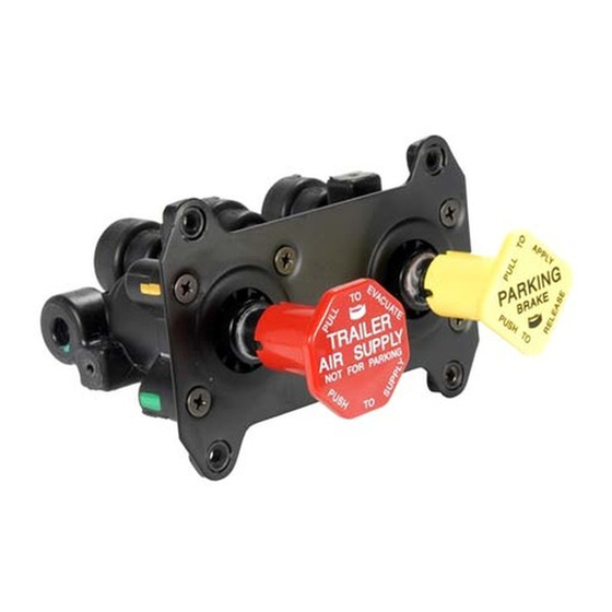
FIGURE 1 - MV-3
DASH CONTROL MODULE
DESCRIPTION
The Bendix
®
MV-3
™
dash control module is a two-button,
push-pull control valve housed in a single body which includes
a dual circuit supply valve and a check valve. The MV-3
valve can duplicate the functions of any existing two or three
valve push-pull system and has the advantages of reduced
plumbing.
™
The MV-3
valve body, plungers and spools are made out of
a non-metallic, non-corrosive material. All air connections
are at the back of the valve with the exception of the optional
auxiliary port as shown in Figure 1.
™
The MV-3
valve provides the following functions:
1 - Tractor Protection.
2 - Trailer Service Air Control.
3 - System Park.
4 - Trailer Park Only.
5 - Trailer Charge with Tractor Spring Brakes Applied (Tractor
Park Only).
6 - Supply Reservoir Selection.
7 - Primary & Secondary Reservoir Connections.
Dash Control Module
TRAILER
DELIVERY
MOUNTING
HOLES
(4)
SECONDARY
SUPPLY
TRACTOR
DELIVERY
AUXILIARY
PORT
(OPTIONAL)
TRAILER
DELIVERY
EXHAUST
™
AUXILIARY
DELIVERY
PORT
DELIVERY
TRAILER
SUPPLY
LINE
TRACTOR
PROTECTION
FIGURE 2 - MV-3
CONNECTIONS
DUAL CIRCUIT
SUPPLY
VALVE
PRIMARY
SUPPLY
BOTTOM VIEW
TRACTOR SERVICE
RESERVOIR #1
EXHAUST
PORT
SUPPLY
#2
TRACTOR
SERVICE
VALVE
RESERVOIR #2
™
DASH CONTROL MODULE AIR
TRACTOR
DELIVERY
SECONDARY
SUPPLY
SUPPLY
#1
DELIVERY
TRACTOR
SPRING
BRAKES
1
Advertisement

Related Manuals for BENDIX MV-3 DASH CONTROL MODULE


Summary of Contents for BENDIX MV-3 DASH CONTROL MODULE
- Page 1 HOLES BOTTOM VIEW ™ FIGURE 1 - MV-3 DASH CONTROL MODULE DESCRIPTION TRACTOR SERVICE RESERVOIR #1 The Bendix ® MV-3 ™ dash control module is a two-button, push-pull control valve housed in a single body which includes EXHAUST ™ a dual circuit supply valve and a check valve. The MV-3...
-
Page 2: Trailer Parking Or Emergency Brakes
OPERATION NORMAL OPERATING POSITION (FIGURE 5) With both buttons pushed in, air is supplied to the trailer During initial charge, with the system completely discharged, and to the tractor spring brakes; all brakes are released. both buttons are out (Figure 3). When system pressure reaches 65 P.S.I., the red button (trailer supply) may be pushed in (Figure 4) and should stay in, charging the trailer system and releasing the trailer brakes. -
Page 3: Automatic Application
This complies with Federal Regulations that one or repair it using genuine Bendix parts. control must apply all the parking brakes on the vehicle. 9. Close all reservoir drain cocks and deliberately caused TRAILER CHARGE (FIGURE 4) leakage points before placing the vehicle in service. -
Page 4: Disassembly Valve
ASSEMBLY DUAL CIRCUIT SUPPLY VALVE 1. Lubricate all o-rings and bores with silicone lubricant. Bendix Pc. No. 291126 or Dow Corning 55-M. VALVE BODY 2. Place the check valve (17) into its seat in the body with its flat surface facing upward. If necessary, reach into... -
Page 5: Final Assembly
3. Install o-rings (24 & 13) onto the check valve (23). Then 4. Repeat Steps 1, 2, and 3 with the remaining components ™ install the assembly into its cavity in the MV-3 valve for the opposite spool. body. SHUTTLE AND CHECK VALVE 4. - Page 6 BW1613 © 2004 Bendix Commercial Vehicle Systems LLC. All rights reserved. 3/2004 Printed in U.S.A.