Table of Contents
Advertisement
TA790GX A2+/TA790GX A2+ SE/TA790GX 128M
Setup Manual
FCC Information and Copyright
This equipment has been tested and found to comply with the limits of a Class
B digital device, pursuant to Part 15 of the FCC Rules. These limits are designed
to provide reasonable protection against harmful interference in a residential
installation. This equipment generates, uses, and can radiate radio frequency
energy and, if not installed and used in accordance with the instructions, may
cause harmful interference to radio communications. There is no guarantee
that interference will not occur in a particular installation.
The vendor makes no representations or warranties with respect to the
contents here and specially disclaims any implied warranties of merchantability
or fitness for any purpose. Further the vendor reserves the right to revise this
publication and to make changes to the contents here without obligation to
notify any party beforehand.
Duplication of this publication, in part or in whole, is not allowed without first
obtaining the vendor's approval in writing.
The content of this user's manual is subject to be changed without notice and
we will not be responsible for any mistakes found in this user's manual. All the
brand and product names are trademarks of their respective companies.
Advertisement
Table of Contents
Troubleshooting

Related Manuals for Biostar TA790GX 128M


Summary of Contents for Biostar TA790GX 128M
- Page 1 TA790GX A2+/TA790GX A2+ SE/TA790GX 128M Setup Manual FCC Information and Copyright This equipment has been tested and found to comply with the limits of a Class B digital device, pursuant to Part 15 of the FCC Rules. These limits are designed to provide reasonable protection against harmful interference in a residential installation.
-
Page 2: Table Of Contents
Table of Contents Chapter 1: Introduction ............1 Before You Start ................1 Package Checklist ................1 Motherboard Features..............2 Rear Panel Connectors ..............4 Motherboard Layout................. 5 Chapter 2: Hardware Installation ..........6 Installing Central Processing Unit (CPU)........6 FAN Headers.................. -
Page 3: Chapter 1: Introduction
TA790GX A2+/TA790GX A2+ SE/TA790GX 128M CHAPTER 1: INTRODUCTION EFORE TART Thank you for choosing our product. Before you start installing the motherboard, please make sure you follow the instructions below: Prepare a dry and stable working environment with sufficient lighting. Always disconnect the computer from power outlet before operation. -
Page 4: Motherboard Features
Motherboard Manual OTHERBOARD EATURES SPEC Socket AM2+ AMD 64 Architecture enables 32 and 64 bit AMD Athlon 64 / Athlon 64 FX / Athlon 64 X2 computing / Sempron / Phenom processors Supports Hyper Transport 3.0 and PowerNow Support HyperTransport 3.0 Supports up to 5.2 GT/s Bandwidth AMD 790GX Chipset... - Page 5 Connect to USB devices Audio Jack Provide Audio-In/Out and microphone connection Board Size 225 mm (W) x 305 mm (L) Biostar Reserves the right to add or remove support OS Support Windows XP / VISTA for any OS With or without notice.
-
Page 6: Rear Panel Connectors
Motherboard Manual ANEL ONNECTORS PS/2 Mouse Port PS/2 Keyboard Port HDMI Port The High-Definition Multimedia Interface (HDMI) is an all-digital audio/video interface capable of transmitting uncompressed streams to an AV receiver or any compatible digital audio and/or video monitor, such as a digital television. DVI-D VGA Port The Digital Visual Interface (DVI) is a video interface transmitting digital video signals to digital display devices such as flat panel LCDs or digital projectors. -
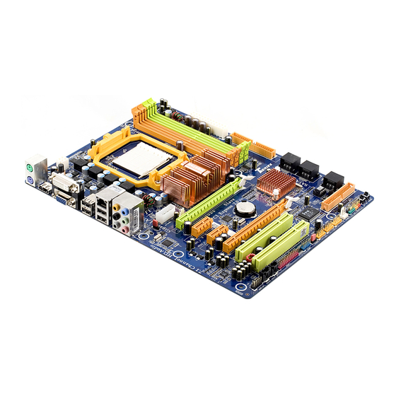
Page 7: Motherboard Layout
TA790GX A2+/TA790GX A2+ SE/TA790GX 128M OTHERBOARD AYOUT JKBMS1 JCFAN1 JATXPWR3 JA TXPWR2 JUSB1 JUSBLAN1 JAUDIO2 790GX J ATXPWR1 JUSBV1 JNFAN1 PEX16_2 SATA3 PEX1_1 BAT1 SB750 PEX1_2 SATA2 LED_D1 PEX16_1 LED_D2 BIOS SATA1 Codec JCMOS1 PCI1 Super I/O JSPDIF_IN1 FDD1 PCI2 JAUDIOF1 JSPDIF_OUT1 JSFAN1... -
Page 8: Chapter 2: Hardware Installation
Motherboard Manual CHAPTER 2: HARDWARE INSTALLATION (CPU) NSTALLING ENTRAL ROCESSING Step 1: Remove the socket protection cap. Step 2: Pull the lever toward direction A from the socket and then raise the lever up to a 90-degree angle. Step 3: Look for the white triangle on socket, and the gold triangle on CPU should point towards this white triangle. - Page 9 TA790GX A2+/TA790GX A2+ SE/TA790GX 128M Step 4: Hold the CPU down firmly, and then close the lever toward direct B to complete the installation. Step 5: Put the CPU Fan on the CPU and buckle it. Connect the CPU FAN power cable to the JCFAN1. This completes the installation. Note: Please update the BIOS to the latest version while using AM2+ CPUs.
-
Page 10: Fan Headers
Motherboard Manual FAN H EADERS These fan headers support cooling-fans built in the computer. The fan cable and connector may be different according to the fan manufacturer. Connect the fan cable to the connector while matching the black wire to pin#1. -
Page 11: Installing System Memory
TA790GX A2+/TA790GX A2+ SE/TA790GX 128M NSTALLING YSTEM EMORY A. DDR2 Modules Unlock a DIMM slot by pressing the retaining clips outward. Align a DIMM on the slot such that the notch on the DIMM matches the break on the Slot. Insert the DIMM vertically and firmly into the slot until the retaining chip snap back in place and the DIMM is properly seated. - Page 12 Motherboard Manual B. Memory Capacity DIMM Socket Total Memory DDR2 Module Location Size DIMMA1 256MB/512MB/1GB/2GB/4GB DIMMB1 256MB/512MB/1GB/2GB/4GB Max is 16GB. DIMMA2 256MB/512MB/1GB/2GB/4GB DIMMB2 256MB/512MB/1GB/2GB/4GB C. Dual Channel Memory installation To trigger the Dual Channel function of the motherboard, the memory module must meet the following requirements: Install memory module of the same density in pairs, shown in the following table.
-
Page 13: Connectors And Slots
TA790GX A2+/TA790GX A2+ SE/TA790GX 128M ONNECTORS AND LOTS FDD1: Floppy Disk Connector The motherboard provides a standard floppy disk connector that supports 360K, 720K, 1.2M, 1.44M and 2.88M floppy disk types. This connector supports the provided floppy drive ribbon cables. IDE1: IDE/ATAPI Connector The motherboard has a 32-bit Enhanced IDE Controller that provides PIO Mode 0~4, Bus Master, and Ultra DMA 33/66/100/133 functionality. - Page 14 Motherboard Manual PEX16_1: PCI-Express Gen2 x16 Slot (x16/x8 Speed) PCI-Express 2.0 compliant. PCI-Express Gen2 supports a raw bit-rate of 5.0Gb/s on the data pins. 2X bandwidth over the PCI-Express 1.1 architecture. x16 Speed Mode: Maximum theoretical realized bandwidth of 8GB/s simultaneously per direction, for an aggregate of 16GB/s totally.
- Page 15 TA790GX A2+/TA790GX A2+ SE/TA790GX 128M PEX1_1/PEX1_2: PCI-Express Gen2 x1 Slots PCI-Express 2.0 compliant. Data transfer bandwidth up to 500MB/s per direction; 1GB/s in total. PCI-Express Gen2 supports a raw bit-rate of 5.0Gb/s on the data pins. 2X bandwidth over the PCI-Express 1.1 architecture. PEX1_ 1 PE X1_ 2 PCI1~PCI2: Peripheral Component Interconnect Slots...
-
Page 16: Chapter 3: Headers & Jumpers Setup
Motherboard Manual CHAPTER 3: HEADERS & JUMPERS SETUP OW TO ETUP UMPERS The illustration shows how to set up jumpers. When the jumper cap is placed on pins, the jumper is “close”, if not, that means the jumper is “open”. Pin opened Pin closed Pin1-2 closed... - Page 17 TA790GX A2+/TA790GX A2+ SE/TA790GX 128M JATXPWR2: ATX Power Source Connector This connector allows user to connect 24-pin power connector on the ATX power supply. Assignment Assignment +3.3V +3.3V -12V +3.3V Ground Ground PS_ON Ground Ground Ground Ground Ground PW_OK Standby Voltage+5V +12V +12V Ground...
-
Page 18: Clear Cmos Procedures
Motherboard Manual JATXPWR1: Auxiliary Power for Graphics This connector is an auxiliary power connection for graphics cards. Exclusive power for the graphics card provides better graphics performance. Assignment +12V Ground Ground JCMOS1: Clear CMOS Header By placing the jumper on pin2-3, it allows user to restore the BIOS safe setting and the CMOS data, please carefully follow the procedures to avoid damaging the motherboard. - Page 19 TA790GX A2+/TA790GX A2+ SE/TA790GX 128M SATA1~SATA3: Serial ATA Connectors The motherboard has a PCI to SATA Controller with 6 channels SATA interface, it satisfies the SATA 2.0 spec and with transfer rate of 3.0Gb/s. SATA1 SATA2 SATA3 JUSB3~JUSB5: Headers for USB 2.0 Ports at Front Panel This header allows user to connect additional USB cable on the PC front panel, and also can be connected with internal USB devices, like USB card reader.
- Page 20 Motherboard Manual JAUDIOF1: Front Panel Audio Header This header allows user to connect the front audio output cable with the PC front panel. This header allows only HD audio front panel connector; AC’97 connector is not acceptable. Assignment Mic Left in Ground Mic Right in GPIO...
- Page 21 TA790GX A2+/TA790GX A2+ SE/TA790GX 128M JCDIN1: CD-ROM Audio-in Connector This connector allows user to connect the audio source from the variaty devices, like CD-ROM, DVD-ROM, PCI sound card, PCI TV turner card etc. Assignment Left Channel Input Ground Ground Right Channel Input JPRNT1: Printer Port Connector This header allows you to connector printer on the PC.
- Page 22 Motherboard Manual JCOM1: Serial port Connector The motherboard has a Serial Port Connector for connecting RS-232 Port. Assignment Carrier detect Received data Transmitted data Data terminal ready Signal ground Data set ready Request to send Clear to send Ring indicator JUSBV1/JUSBV2: Power Source Headers for USB Ports Pin 1-2 Close: JUSBV1: +5V for USB ports at JUSB1/JUSBLAN1.
- Page 23 TA790GX A2+/TA790GX A2+ SE/TA790GX 128M On-Board LED Indicators There are 2 LED indicators on the motherboard to show system status. LED_D1 LED_D2 LED_D1 and LED_D2: These 2 LED indicate system power on diagnostics. Please refer to the table below for different messages: LED_D2 LED_D1 Message...
-
Page 24: Chapter 4: (Hybrid) Crossfirex Function
Motherboard Manual CHAPTER 4: (HYBRID) CROSSFIREX FUNCTION ROSS EQUIREMENTS Only Windows XP/Vista supports CrossFireX (Dual Video) function. A pair of graphics cards with Radeon HD3650/HD3850/HD3870/HD4850/ HD4870 GPU. The graphics card driver should support CrossFireX technology. The power supply unit must provide at least the minimum power required by the system, or the system will be unstable. -
Page 25: Hybrid Crossfirex Requirements
TA790GX A2+/TA790GX A2+ SE/TA790GX 128M YBRID ROSS EQUIREMENTS Only Windows Vista supports Hybrid CrossFireX function. A graphics card with Radeon HD3450/HD3470 GPU. The graphics card driver should support Hybrid CrossFireX technology. The power supply unit must provide at least the minimum power required by the system, or the system will be unstable. -
Page 26: Operation Modes Supporting List
Motherboard Manual PERATION ODES UPPORTING Operation Mode Single Card CrossFireX Hybrid CrossFireX Model Radeon HD3650 Radeon HD3850 Radeon HD3870 Radeon HD4850 Radeon HD4870 Radeon HD3450 Radeon HD3470 Radeon HD3870X2 (O means Supported, X means Not Supported.) -
Page 27: Chapter 5: Raid Functions
TA790GX A2+/TA790GX A2+ SE/TA790GX 128M CHAPTER 5: RAID FUNCTIONS PERATION YSTEM Supports Windows XP and Windows VISTA. RRAYS RAID supports the following types of RAID arrays: RAID 0: RAID 0 defines a disk striping scheme that improves disk read and write times for many applications. - Page 28 Motherboard Manual RAID 1: Every read and write is actually carried out in parallel across 2 disk drives in a RAID 1 array system. The mirrored (backup) copy of the data can reside on the same disk or on a second redundant drive in the array.
- Page 29 TA790GX A2+/TA790GX A2+ SE/TA790GX 128M RAID 1+0: RAID 1 drives can be stripped using RAID 0 techniques. Resulting in a RAID 1+0 solution for improved resiliency, performance and rebuild performance. Features and Benefits Drives: Minimum 4, and maximum is 6 or 8, depending on the platform. ...
- Page 30 Motherboard Manual RAID 5: RAID 5 stripes both data and parity information across three or more drives. It writes data and parity blocks across all the drives in the array. Fault tolerance is maintained by ensuring that the parity information for any given block of data is placed on a different drive from those used to store the data itself.
-
Page 31: Chapter 6: T-Series Bios & Software
TA790GX A2+/TA790GX A2+ SE/TA790GX 128M CHAPTER 6: T-SERIES BIOS & SOFTWARE BIOS ERIES T-Series BIOS Features Overclocking Navigator Engine (O.N.E.) Memory Integration Test (M.I.T., under Overclock Navigator Engine) BIO-Flasher: Update BIOS file from USB Flash Drive or FDD Self Recovery System (S.R.S) Smart Fan Function CMOS Reloading Program !! WARNING !! - Page 32 Motherboard Manual Manual Overclock System (M.O.S.) MOS is designed for experienced overclock users. It allows users to customize personal overclock settings. BIOS SETUP UTILITY Main Advanced PCIPnP Boot Chipset T-Series Exit T-Series Settings Options WARNING: Setting wrong values in below sections Normal may cause system to malfunction.
-
Page 33: Dram Timing Configuration
TA790GX A2+/TA790GX A2+ SE/TA790GX 128M CPU Frequency CPU Frequency is directly in proportion to system performance. To maintain the system stability, CPU voltage needs to be increased also when raising CPU frequency. CPU FID/VID Control Enter this function for more advanced CPU settings. DRAM Timing Configuration Enter this function for more advanced DRAM clock settings. - Page 34 Motherboard Manual V6 Tech Engine This engine will make a good over-clock performance. BIOS SETUP UTILITY Main Advanced PCIPnP Boot Chipset T-Series Exit T-Series Settings Options WARNING: Setting wrong values in below sections V6-Tech Engine may cause system to malfunction. V8-Tech Engine V12-Tech Engine OverClock Navigator...
- Page 35 TA790GX A2+/TA790GX A2+ SE/TA790GX 128M Notices: Not all types of AMD CPU perform above overclock setting ideally; the difference will be based on the selected CPU model. B. Memory Integration Test (M.I.T.) This function is under “Overclocking Navigator Engine” item. MIT allows users to test memory compatibilities, and no extra devices or software are needed.
- Page 36 Motherboard Manual C. BIO-Flasher BIO-Flasher is a BIOS flashing utility providing you an easy and simple way to update your BIOS via USB pen drive or floppy disk. The BIO-Flasher is built in the BIOS chip. To enter the utility, press <F12> during the Power-On Self Tests (POST) procedure while booting up.
- Page 37 TA790GX A2+/TA790GX A2+ SE/TA790GX 128M D. Self Recovery System (S.R.S.) This function can’t be seen under BIOS setup; and is always on whenever the system starts up. However, it can prevent system hang-up due to inappropriate overclock actions. When the system hangs up, S.R.S. will automatically log in the default BIOS setting, and all overclock settings will be re-configured.
- Page 38 Motherboard Manual Smart Fan Calibration Choose this item and then the BIOS will automatically test and detect the CPU/System fan functions and show CPU/System fan speed. Control Mode This item provides several operation modes of the fan. Fan Ctrl OFF(℃) If the CPU/System temperature is lower than the set value, the CPU/ System fan will turn off.
-
Page 39: T-Series Software
TA790GX A2+/TA790GX A2+ SE/TA790GX 128M ERIES OFTWARE Installing T-Series Software 1. Insert the Setup CD to the optical drive. The drivers installation program would appear if the Auto-run function has been enabled. 2. Select Software Installation, and then click on the respective software title. - Page 40 Motherboard Manual Over Clock Panel Restore Default Settings AUTO Over-Clock V3/V6/V9 Engine Real-time Ove r-clock Manual Adjust CPU Clock Test & Apply Manual Setting s AUTO User can click this button and the utility will set the best and stable performance and frequency automatically.
- Page 41 TA790GX A2+/TA790GX A2+ SE/TA790GX 128M Then the utility will execute a series of testing until system fail. Then system will do fail-safe reboot by using Watchdog function. After reboot, launch the utility again and the utility will load the previously verified best and stable frequency.
- Page 42 Motherboard Manual Over Voltage Panel Manual Adjust CPU/Memo ry/Chipset/FSB Voltage CPU Voltage This function allows user to adjust CPU voltage. Click on “+” to increase or “-“ to decrease the CPU voltage. Memory Voltage This function allows user to adjust Memory voltage. Click on “+” to increase or “-“...
-
Page 43: Hardware Monitor
TA790GX A2+/TA790GX A2+ SE/TA790GX 128M About Panel In this panel, you can get model name and other system information that may related to over-clocking. You can also get the version number of this software. Note Because the Over Clock and Over Voltage features are controlled by several separate chipset, the utility divides these features to separate... - Page 44 Motherboard Manual eHot-Line (Optional) eHot-Line is a convenient utility that helps you to contact with our Tech-Support system. This utility will collect the system information which is useful for analyzing the problem you may have encountered, and then send these information to our tech-support department to help you fix the problem. Before you use this utility, please set Outlook Express as your default e-mail client application program.
- Page 45 If you are not using Outlook Express as your default e-mail client application, you may need to save the system information to a .txt file and send the file to our tech support with other e-mail application. Go to the following web http://www.biostar.com.tw/app/en-us/about/contact.php for getting our contact information.
-
Page 46: Bios Update
Motherboard Manual BIOS Update BIOS Update is a convenient utility which allows you to update your motherboard BIOS under Windows system. Show current BIOS information AWARD BIOS AMI BIOS Online Update function Clear CMOS function (Only for AMI BIOS) (Only for AWARD BIOS) Save current BIOS to a .bin file Update BIOS... - Page 47 TA790GX A2+/TA790GX A2+ SE/TA790GX 128M <Update BIOS> Before doing this, please download the proper BIOS file from the website. For AWARD BIOS, update BIOS procedure should be run with Clear CMOS function, so please check on Clear CMOS first. Then click Update BIOS button, a dialog will show for asking you backup current BIOS.
- Page 48 Motherboard Manual <Online Update> (for AMI BIOS only) Automatically download and update the latest BIOS via internet; make sure that the computer is connected to the internet before using this function. After clicking on the Onlinr Update button, the utility will search for the latest BIOS from internet.
-
Page 49: Chapter 7: Useful Help
TA790GX A2+/TA790GX A2+ SE/TA790GX 128M CHAPTER 7: USEFUL HELP RIVER NSTALLATION After you installed your operating system, please insert the Fully Setup Driver CD into your optical drive and install the driver for better system performance. You will see the following window after you insert the CD The setup guide will auto detect your motherboard and operating system. -
Page 50: Extra Information
Motherboard Manual XTRA NFORMATION CPU Overheated If the system shutdown automatically after power on system for seconds, that means the CPU protection function has been activated. When the CPU is over heated, the motherboard will shutdown automatically to avoid a damage of the CPU, and the system may not power on again. -
Page 51: Ami Bios Beep Code
TA790GX A2+/TA790GX A2+ SE/TA790GX 128M AMI BIOS B Boot Block Beep Codes Number of Beeps Description No media present. (Insert diskette in floppy drive A:) “AMIBOOT.ROM” file not found in root directory of diskette in Insert next diskette if multiple diskettes are used for recovery Flash Programming successful File read error No Flash EPROM detected... -
Page 52: Troubleshooting
Motherboard Manual ROUBLESHOOTING Probable Solution No power to the system at all Make sure power cable is Power light don’t illuminate, fan securely plugged in. inside power supply does not turn Replace cable. Contact technical support. Indicator light on keyboard does not turn on. - Page 53 TA790GX A2+/TA790GX A2+ SE/TA790GX 128M This page is intentionally left blank.
-
Page 54: Appendix: Spec In Other Language
Motherboard Manual APPENDIX: SPEC IN OTHER LANGUAGE ERMAN Spezifikationen Sockel AM2+ Die AMD 64-Architektur unterstützt eine 32-Bit- und AMD Athlon 64 / Athlon 64 FX / Athlon 64 64-Bit-Datenverarbeitung X2 / Sempron / Phenom Prozessoren Unterstützt Hyper Transport 3.0 und PowerNow Unterstützt HyperTransport 3.0 mit einer Bandbreite von bis zu 5.2 GT/s AMD 790GX... - Page 55 PS/2-Tastatur PS/2-Maus HDMI-Anschluss Rückseiten-E VGA-Anschluss DVI-D-Anschluss LAN-Anschluss USB-Anschluss Audioanschluss Platinengröße 225 mm (B) X 305 mm (L) Biostar behält sich das Recht vor, ohne Ankündigung OS-Unterstüt Windows XP / VISTA die Unterstützung für ein Betriebssystem zung hinzuzufügen oder zu entfernen.
-
Page 56: France
Motherboard Manual RANCE SPEC Socket AM2+ L'architecture AMD 64 permet le calcul 32 et 64 bits Processeurs AMD Athlon 64 / Athlon 64 FX / Prend en charge Hyper Transport 3.0 et PowerNow Athlon 64 X2 / Sempron / Phenom Prend en charge Hyper Transport 3.0 jusqu'à... - Page 57 Port LAN Port USB Fiche audio Dimensions 225 mm (l) X 305 mm (H) de la carte Biostar se réserve le droit d'ajouter ou de supprimer Support SE Windows XP / VISTA le support de SE avec ou sans préavis.
-
Page 58: Italian
Motherboard Manual TALIAN SPECIFICA Socket AM2+ L’architettura AMD 64 abilita la co mputazione 32 Processori AMD Athlon 64 / Athlon 64 e 64 bit FX / Athlon 64 X2 / Sempron / Supporto di Hyper Transport 3.0 e PowerNow Phenom Supporto di HyperTransport 3.0 fino a 5.2 GT/s di larghezza di banda AMD 790GX... - Page 59 Porta LAN Porta USB Connettore audio Dimension 225 mm (larghezza) x 305 mm i scheda (altezza) Sistemi Biostar si riserva il diritto di aggiungere o operativi Windows XP / VISTA rimuovere il supporto di qualsiasi sistema supportati operativo senza preavviso.
-
Page 60: Spanish
Motherboard Manual PANISH Especificación La arquitectura AMD 64 permite el procesado de 32 y Conector AM2+ 64 bits Procesadores AMD Athlon 64 / Athlon 64 Soporta las tecnologías Hyper Transport 3.0 y FX / Athlon 64 X2 / Sempron / Phenom PowerNow Admite HyperTransport 3.0 con un ancho de banda de hasta 5.2 GT/s... - Page 61 Conector de sonido Tamaño de 225 mm. (A) X 305 mm. (H) la placa Soporte de Biostar se reserva el derecho de añadir o retirar el sistema Windows XP / VISTA soporte de cualquier SO con o sin aviso previo. operativo...
-
Page 62: Portuguese
Motherboard Manual ORTUGUESE ESPECIFICAÇÕES A arquitectura AMD 64 permite uma computação de 32 Socket AM2+ e 64 bits Processadores AMD Athlon 64 / Athlon 64 Suporta as tecnologias Hyper Transport 3.0 e FX / Athlon 64 X2 / Sempron / Phenom PowerNow Suporta a tecnologia HyperTransport 3.0 com uma largura de banda até... - Page 63 Porta USB Tomada de áudio Tamanho 225 mm (L) X 305 mm (A) da placa Sistemas A Biostar reserva-se o direito de adicionar ou remover operativos Windows XP / VISTA suporte para qualquer sistema operativo com ou sem suportados aviso prévio.
-
Page 64: Polish
Motherboard Manual OLISH SPEC Socket AM2+ Architektura AMD 64 umożliwia przetwarzanie Procesor AMD Athlon 64 / Athlon 64 FX / Athlon 64 X2 / 32 i 64 bitowe Sempron / Phenom Procesory Obsługa Hyper Transport 3.0 oraz PowerNow Obsługa HyperTransport 3.0 o szerokości pasma do 5.2 GT/s AMD 790GX Chipset... - Page 65 Back Panel Port VGA Port DVI-D Port LAN Port USB Gniazdo audio Wymiary 225 mm (S) X 305 mm (W) płyty Obsluga Biostar zastrzega sobie prawo dodawania lub systemu odwoływania obsługi dowolnego systemu Windows XP / VISTA operacyjne operacyjnego bez powiadomienia.
-
Page 66: Russian
Motherboard Manual USSIAN СПЕЦ Гнездо AM2+ Архитектура AMD 64 разрешать обработка (центральн Процессоры AMD Athlon 64 / Athlon 64 FX / данных на 32 и 64 бит ый Athlon 64 X2 / Sempron / Phenom Поддержка Hyper Transport 3.0 и PowerNow процессор) Поддержка... - Page 67 ввода-выв Порт LAN USB-порт ода Гнездо для подключения наушников Размер 225 мм (Ш) X 305 мм (В) панели Biostar сохраняет за собой право добавлять или Поддержка Windows XP / VISTA удалять средства обеспечения для OS с или без предварительного уведомления.
-
Page 68: Arabic
Motherboard Manual RABIC اﻟﻤﻮاﺻﻔﺎت ﻡﻘﺒﺲAM2+ ﺗﻤﻜﻦ ﺗﻘﻨﻴﺔAMD 64 ﺖ ﺏ و إﺝﺮاء اﻟﻌﻤﻠﻴﺎت اﻟﺤﺎﺳﻮﺏﻴﺔ ﺏﺴﺮﻋﺔ وﺣﺪة اﻟﻤﻌﺎﻟﺠﺔ ﻡﻌﺎﻟﺠﺎتAMD Athlon 64 / Athlon 64 FX / Athlon 64 ﺗﺪﻋﻢ ﺗﻘﻨﻴﺔHyper Transport 3.0 PowerNow و اﻟﻤﺮآﺰﻳﺔ X2 / Sempron / Phenom 5.2 GT/s ﺗﺪﻋﻢ... - Page 69 ﻡﻨﺎﻓﺬ اﻟﻠﻮﺣﺔ اﻟﺨﻠﻔﻴﺔ ﻋﺪ ﻡﻨﻔﺬ ﺵﺒﻜﺔ اﺗﺼﺎل ﻡﺤﻠﻴﺔ ﻋﺪد ﻡﻨﺎﻓﺬ ﻋﺪد ﻡﻘﺒﺲ ﺹﻮت ارﺗﻔﺎع ﻡﻢ ﻋﺮض ﻡﻢ ﺣﺠﻢ اﻟﻠﻮﺣﺔ ﺗﺤﺘﻔﻆBiostar إﺿﺎﻓﺔ أو إزاﻟﺔ اﻟﺪﻋﻢ ﻷي ﻥﻈﺎم ﺗﺸﻐﻴﻞ ﺏﺈﺥﻄﺎر أو ﺏﺤﻘﻬﺎ ﻓﻲ Windows XP / VISTA دﻋﻢ أﻥﻈﻤﺔ اﻟﺘﺸﻐﻴﻞ ﺏﺪون إﺥﻄﺎر...
-
Page 70: Japanese
Motherboard Manual APANESE 仕様 AMD 64アーキテクチャでは、 32ビットと64ビット計算が Socket AM2+ 可能です AMD Athlon 64 / Athlon 64 FX / Athlon 64 X2 ハイパートランスポート3.0とクールアンドクワイアット / Sempron / Phenom プロセッサ をサポートします 5.2 GT/sのバンド幅までハイパートランスポート 3.0をサポートします AMD 790GX チップセット AMD SB750 DDR2 DIMMスロット x 4 デュアル... - Page 71 オンボードコ S/PDIFインコネクタ デジタルオーディオイン機能をサポートします ネクタ CPUファンヘッダ CPUファン電源装置(スマートファン機能を搭載) システムファンヘッダ システムファン電源装置 CMOSクリアヘッダ 各コネクタは2つのフロントパネルUSBポートをサポート USBコネクタ します シリアルポート 電源コネクタ(24ピン) 電源コネクタ(4ピン) PS/2キーボード PS/2マウス HDMIポート VGAポート 背面パネル DVI-Dポート LANポート USBポート オーディオジャック ボードサイズ 225 mm (幅) X 305 mm (高さ) Biostarは事前のサポートなしにOSサポートを追加または OSサポート Windows XP / VISTA 削除する権利を留保します。 2008/08/05...