Biostar K8M800 MICRO AM2 User Manual
Hide thumbs
Also See for K8M800 MICRO AM2:
- Bios setup manual (43 pages) ,
- Setup manual (51 pages) ,
- Manual (71 pages)
Table of Contents
Advertisement
K8M800 Micro AM2 Setup Manual
FCC Information and Copyright
This equipment has been tes ted and found to comply with the limits of a Class
B digital devic e, purs uant to Part 15 of the FCC Rules . T hese limits are designed
to provide reasonable protec tion against harmful interference in a residential
installation. T his equipment generates , uses and can radiate radio frequency
energy and, if not ins talled and used in accordance with the instructions , may
cause harmful interference to radio communications . There is no guarantee
that interference will not occur in a particular ins tallation.
The vendor makes no representations or warranties with respec t to the
contents here and s pecially disclaims any implied warranties of merchantability
or fitness for any purpose. Further the vendor reserves the right to revise this
publication and to make c hanges to the c ontents here without obligation to
notify any party beforehand.
D uplication of this publication, in part or in whole, is not allowed without first
obtaining the vendor's approval in writing.
The content of this user's manual is subject to be c hanged without notice and
we will not be res ponsible for any mis takes found in this user's manual. All the
brand and produc t names are trademarks of their respec tive companies .
Advertisement
Chapters
Table of Contents

Related Manuals for Biostar K8M800 MICRO AM2


Summary of Contents for Biostar K8M800 MICRO AM2
- Page 1 K8M800 Micro AM2 Setup Manual FCC Information and Copyright This equipment has been tes ted and found to comply with the limits of a Class B digital devic e, purs uant to Part 15 of the FCC Rules . T hese limits are designed to provide reasonable protec tion against harmful interference in a residential installation.
-
Page 2: Table Of Contents
Table of Contents Chapter 1: Introduction ..........1 Before You Start..............1 Package Checklist..............1 Motherboard Features............2 Rear Panel Connectors............3 Motherboard Layout ............4 Chapter 2: Hardware Installation ......5 Installing Central Processing Unit (CPU) ........ 5 FAN Headers................ 7 Installing System Memory............ -
Page 3: Chapter 1: Introduction
K8M800 Micro A M2 CHAPTER 1: INTRODUCTION EFORE T ART Thank you for choosing our product. Be fore you start installing the mothe rboard, please make sure you follow the instructions be low: Prepare a dry and stable work ing environment with sufficie nt lighting. -
Page 4: Motherboard Features
Motherboard Manual OT HERBOARD EAT URES SPEC Socket AM2 Supports Hyper Tran sport and Cool=n =Quiet AMD Sempron processors Support HyperTran sport Supports up to 800 MHz Bandwidth K8M800 Chipset VT8237R+ Environ men t Con trol in itiatives, ITE IT8705 H/W Mon itor Provides the most commonly u sed legacy Super I/O... -
Page 5: Rear Panel Connectors
Board Size 197 x 243 (mm) Micro ATX Size Board Special RAID 0 / 1 support Features Biostar Reserves the righ t to add or remove support for OS Support Windows 2000 / XP any OS With or without notice. ANEL ONNECT ORS... -
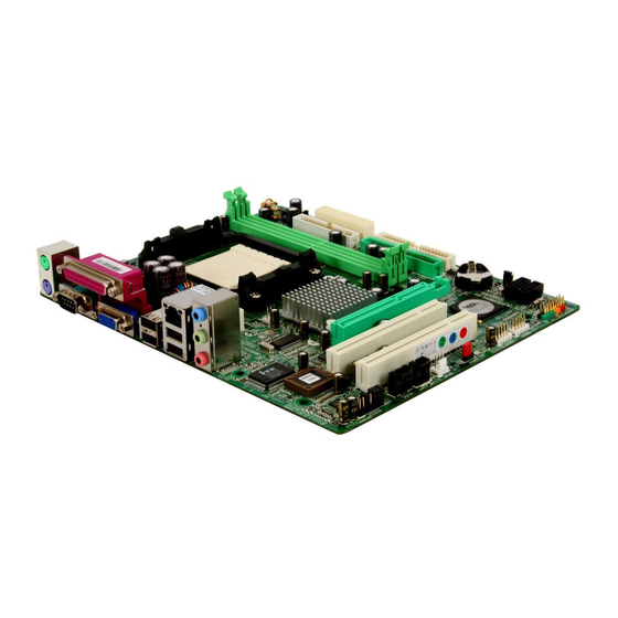
Page 6: Motherboard Layout
Motherboard Manual OT HERBOARD AYOUT JKBMS1 JATXPWR1 JUSB1 JA TXPWR2 JCFAN1 JUSBLAN1 JAUDIO1 K8M800 BAT1 Super I/O AGP1 JCMOS1 BIOS PCI1 VT8237R+ JSATA2 PCI2 JSAT A1 Codec JAUDIO2 JCDIN1 JSPDIF_OUT1 JSFAN1 JUSB2 JUSB3 JP ANEL1 Not e: ■ repre sents the 1 pin. -
Page 7: Chapter 2: Hardware Installation
K8M800 Micro A M2 CHAPTER 2: HARDWARE INSTALLATION (CPU) NST ALLING ENT RAL ROCESSING Step 1: Remove the socket protection cap. Step 2: Pull the lever toward direction A from the socket and then raise the lever up to a 90-degree angle. Step 3: Look for the white triangle on socket, and the gold triangle on CPU should point towards this white triangle. - Page 8 Motherboard Manual Step 4: Hold the CPU down firmly, and then close the lever toward direct B to complete the installation. Step 5: Put the CPU Fan on the CPU and buckle it. Connect the CPU FAN power cable to the JCFAN1. This completes the installation.
-
Page 9: Fan Headers
K8M800 Micro A M2 FAN H EADERS These fan headers support cooling-fans built in the computer. The fan cable and connector may be different according to the fan manufacturer. Connect the fan cable to the connector while matching the black wire to pin#1. -
Page 10: Installing System Memory
Motherboard Manual NST ALLING YST EM EMORY A. DDR2 module DIMMA1 DIMMB1 Unlock a DIMM slot by pressing the retaining clips outward. Align a DIMM on the slot such that the notch on the DIMM matches the break on the Slot. Insert the DIMM vertically and firmly into the slot until the retaining chip snap back in place and the DIMM is properly seated. - Page 11 K8M800 Micro A M2 C. Dual Channel Memory installation To trigger the Dual Channel f unction of the motherboard, the memory module must meet the following requirements: Install memory module of the same density in pair, shown in the following table. DIMMA1 Dual Channel Status DIMMB1...
-
Page 12: Connectors And Slots
Motherboard Manual ONNECT ORS AND LOT S FDD1: Floppy Disk Conne ctor The motherboard prov ides a standard floppy disk connector that supports 360K, 720K, 1.2M, 1.44M and 2.88M floppy disk ty pes. This connector supports the prov ided f loppy drive ribbon cables. IDE1/IDE2: Hard Disk Conne ctors The motherboard has a 32-bit Enhanced PCI IDE Controller that prov ides PIO Mode 0~4, Bus Master, and Ultra DMA 33/66/100/133 f unctionality. - Page 13 K8M800 Micro A M2 PCI1~PCI2: Pe riphe ral Component Interconne ct Slots This motherboard is equipped with 2 standard PCI slots. PCI stands for Peripheral Component Interconnect, and it is a bus standard for expansion cards. This PCI slot is designated as 32 bits. PCI1 PCI2 AGP1: Accele rate d Graphics Port Slot...
-
Page 14: Chapter 3: Headers & Jumpers Setup
Motherboard Manual CHAPTER 3: HEADERS & JUMPERS SETUP OW T O ET UP UMPERS The illustration shows how to set up jumpers. When the jumper cap is placed on pins, the jumper is “close”, if not, that means the jumper is “open”. - Page 15 K8M800 Micro A M2 JATXPWR1: ATX Powe r Source Conne ctor This connector allows user to connect 20-pin power connector on the ATX power supply. Assignment +3.3V +3.3V Ground JATXPWR1 Ground Ground PW_OK Standby Voltage +12V +3.3V -12V Ground PS_ON Ground Ground Ground...
- Page 16 Motherboard Manual JUSB1/JUSB2: Heade rs for USB 2.0 Ports at Front Panel This motherboard prov ides 2 USB 2.0 headers, which allows user to connect additional USB cable on the PC front panel, and also can be connected with internal USB dev ices, like USB card reader. Assignment +5V (fused) +5V (fused)
-
Page 17: Clear Cmos Header/Procedures
K8M800 Micro A M2 JCDIN1: CD-RO M Audio-in Connector This connector allows user to connect the audio source f rom the v ariaty dev ices, like CD-ROM, DVD-ROM, PCI sound card, PCI TV turner card etc.. Assignment Left Channel Input Ground Ground Right Channel... - Page 18 Motherboard Manual JSATA1~JSATA2: Se rial ATA Conne ctors The motherboard has a PCI to SATA Controller with 2 channels SATA interface, it satisfies the SATA 1.0 spec and with transfer rate of 1.5Gb/s. Assignment Ground T X+ JSATA1 JSATA2 T X- Ground Ground JSPDIF_O UT1: Digital Audio out Conne ctors...
-
Page 19: Chapter 4: Raid Functions
K8M800 Micro A M2 CHAPTER 4: RAID FUNCTIONS PERAT ION YST EM Supports Windows XP Home/Prof essional Edition, and Windows 2000 Professional. RRAYS RAID supports the following types of RAID arrays: RAID 0: RAID 0 defines a disk striping scheme that improves disk read and write times for many applications. - Page 20 Motherboard Manual RAID 1: Every read and write is actually carried out in parallel across 2 disk drives in a RAID 1 array system. The mirrored (backup) copy of the data can reside on the same disk or on a second redundant drive in the array. RAID 1 provides a hot-standby copy of data if the active volume or drive is corrupted or becomes unavailable because of a hardware failure.
-
Page 21: Chapter 5: Useful Help
K8M800 Micro A M2 CHAPTER 5: USEFUL HELP RIVER NST ALLAT ION OT E After you installed your operating system, please insert the Fully Setup Driver CD into your optical drive and install the driver for better system performance. You will see the following window after you insert the CD The setup guide will auto detect your motherboard and operating system. -
Page 22: Award Bios Beep Code
BIOS contents are corrupted. In this Case, please follow the procedure below to restore the BIOS: 1. Make a bootable floppy disk. 2. Download the Flash Utility “AWDFLASH.exe” from the Biostar website: www.biostar.com.tw 3. Confirm motherboard model and download the respectively BIOS from Biostar website. - Page 23 K8M800 Micro A M2 B. CPU Overheated If the system shutdown automatically after power on system for seconds, that means the CPU protection function has been activated. When the CPU is over heated, the motherboard will shutdown automatically to avoid a damage of the CPU, and the system may not power on again.
-
Page 24: Troubleshooting
Motherboard Manual ROUBLESHOOT ING Probable Solution No power to the system at all Make sure power cable is Power light don’t illuminate, f an securely plugged in. inside power supply does not turn Replace cable. Contact technical support. Indicator light on key board does not turn on. -
Page 25: Chapter 6: Warpspeeder
K8M800 Micro A M2 WARPSPEEDER™ CHAPTER 6: NT RODUCT ION [WarpSpeeder™], a new powerful control utility, features three user-friendly functions including Overclock Manager, Overvoltage Manager, and Hardware Monitor. With the Overclock Manager, users can easily adjust the frequency they prefer or they can get the best CPU performance with just one click. The Overvoltage Manager, on the other hand, helps to power up CPU core voltage and Memory voltage. -
Page 26: Installation
Motherboard Manual NST ALLAT ION 1. Execute the setup execution file, and then the following dialog will pop up. Please click “Next” button and follow the default procedure to install. 2. When you see the following dialog in setup procedure, it means setup is completed. -
Page 27: Warpspeeder
K8M800 Micro A M2 6.4 W ™ PEEDER 1. Tray Icon: Whenever the Tray Icon utility is launched, it will display a little tray icon on the right side of Windows Taskbar. This utility is responsible for conveniently invoking [WarpSpeeder™] Utility. - Page 28 Motherboard Manual 2. Main Panel If you click the tray icon, [WarpSpeeder™] utility will be invoked. Please refer to the following figure; the utility’s first window you will see is Main Panel. Main Panel contains fe ature s as follows: a.
- Page 29 K8M800 Micro A M2 3. Voltage Panel Click the Voltage button in Main Panel, the button will be highlighted and the Voltage Panel will slide out to up as the following figure. In this panel, you can decide to increase CPU core voltage and Memory voltage or not.
- Page 30 Motherboard Manual 4. Overclock Panel Click the Overclock button in Main Panel, the button will be highlighted and the Overclock Panel will slide out to left as the following figure. O ve rclock Panel contains the these features: a. “–3MHz button”, “-1MHz button”, “+1MHz button”, and “+3MHz button”: provide user the ability to do real-time overclock adjustment.
- Page 31 K8M800 Micro A M2 “Auto-overclock button”: User can click this button and [WarpSpeeder™] will set the best and stable performance and frequency automatically. [WarpSpeeder™] utility will execute a series of testing until system fail. Then system will do fail-safe reboot by using Watchdog function. After reboot, the [WarpSpeeder™] utility will restore to the hardware default setting or load the verified best and stable frequency according to the Recovery Dialog’s setting.
- Page 32 Motherboard Manual 6. About Panel Click the “about” button in Main Panel, the button will be highlighted and the About Panel will slide out to up as the following figure. In this panel, you can get model name and detail information in hints of all the chipset that are related to overclocking.
- Page 33 K8M800 Micro A M2 This page is intentionally left blank...
-
Page 34: Appendencies: Spec In Other Language
Motherboard Manual APPENDENCIES: SPEC IN OTHER LANGUAGE ERMAN Spezifikationen Sockel AM2 Unterstü tzt Hyper Tran sport und Cool’n’Qu iet AMD Sempron Prozessoren Unterstü tzt HyperTran sport mit einer Bandbreite von bis zu 800 MHz K8M800 Chipsatz VT8237R+ Umgebungskon trolle, ITE IT8705 Hardware-Überwachung Bietet die häufig verwendeten alten Super E/A... - Page 35 197 mm (B) X 243 mm (L) Sonderfun kti Unterstü tzt RAID 0 / 1 onen Biostar behält sich das Rech t vor , ohne An kündigung die OS-Un terstüt Windows 2000 / XP Unterstü tzung für ein Betriebssystem hin zuzufügen zung oder zu entfernen .
-
Page 36: France
Motherboard Manual RANCE SPEC Socket AM2 Prend en charge Hyper Tran sport et Cool’n ’Quiet Processeu rs AMD Sempron Prend en charge Hyper Tran sport ju squ'à Bus f rontal une bande passan te de 800 MHz K8M800 Chipset VT8237R+ ITE IT8705 Initiatives de contrôle environnemen tales, Fourn it la fon ctionnalité... - Page 37 197 mm (l) X 243 mm (H) de la carte Fonctionnali Prise en charge RAID 0 / 1 tés spéciales Biostar se réserve le droit d'ajouter ou de supprimer le Support SE Windows 2000 / XP support de SE avec ou san s préavis.
-
Page 38: Italian
Motherboard Manual T ALIAN SPECIFICA Socket AM2 Supporto di Hyper Tra nsport e Cool’ n’Quiet Processori AMD Sempro n Supporto di Hy per Transport fino a800 MHz di lar ghezza di ba nda K8M800 Chipset VT8237R+ ITE IT8705 Funzioni di co ntrollo dell’ambiente: Fornisce le funzio nalità... - Page 39 197 mm (larghezza) x 243 mm i scheda (altezza) Caratterist Supporto RAID 0 / 1 iche speciali Sistemi Biostar si riserva il diritto di aggiungere o operativi Windows 2000 / XP rimuovere il supporto di qualsiasi sistema supportati operativo se nza pre avviso.
-
Page 40: Spanish
Motherboard Manual PANISH Especificación Conector AM2 Soporta las tecnologías Hyper T ran sport y Cool’n’Qu iet Procesadores AMD Sempron Admite HyperTran sport con un an cho de banda de hasta800 MHz K8M800 Conjunto de VT8237R+ chips ITE IT8705 Iniciativas de control de entorno, Le of rece las fun cion alidades heredadas de Monitor hardware Súper E/S... - Page 41 197 mm. (A) X 243 Mm. (H) la placa Funciones Admite RAID 0 / 1 especiales Soporte de Biostar se reserva el derecho de añ adir o retirar el sistema Windows 2000 / XP soporte de cualquier SO con o sin aviso previo. operativo...
-
Page 42: Portuguese
Motherboard Manual ORT UGUESE ESPECIFICAÇÕ ES Socket AM2 Suporta as tecn ologias Hyper Tran sport e Cool’n ’Qu iet Processadores AMD Sempron Suporta a tecnologia HyperT ransport com uma largura de banda até800 MHz K8M800 Chipset VT8237R+ ITE IT8705 Iniciativas para controlo do ambien te Proporciona as funcionalidades mais Monitorização do hardware Especif icaçã... - Page 43 197 mm (L) X 243 mm (A) da placa Característi Suporta as funções RAID 0 / 1 especiais Sistemas A Biostar reserva-se o direito de adicionar ou remover operativos Windows 2000 / XP suporte para qualquer sistema operativo com ou sem suportados aviso prévio.
-
Page 44: Polish
Motherboard Manual OLISH SPEC Socket AM2 Procesor Obsługa Hyper T ransport oraz Cool’n ’Qu iet AMD Sempron Procesory Obsługa HyperT ran sport o szerokości pasma do800 MHz K8M800 Chipset VT8237R+ Gniazda DDR2 DIMM x 2 Moduł pamięci DDR2 z trybem podwójnego kanału Pamięć... - Page 45 Wymiary 197 mm (S) X 243 mm (W) płyty Funkcj e Obsługa RAID 0 / 1 specjaln e Obsluga Biostar zastrzega sobie prawo dodawania lub systemu Windows 2000 / XP odwoływania obsługi dowoln ego systemu operacyjne operacyjnego bez powiadomien ia.
-
Page 46: Russian
Motherboard Manual USSIAN СПЕЦ. Гнездо AM2 (центральн Поддержка Hyper Tran sport и Cool’n’Qu iet ый Процессоры AMD Sempron процессор) Поддержка HyperTran sport с пропускной способностью до800MГц K8M800 Набор VT8237R+ микросхем Слоты DDR2 DIMM x 2 Модуль памяти с двухканальн ым режимом DDR2 Основная... - Page 47 197 мм (Ш) X 243 мм (В) панели Специальн ые технически Поддержка RAID 0 / 1 е характери с тики Biostar сохран яет за собой право добавлять или Поддержка Windows 2000 / XP удалять средства обеспечения для OS с или без предварительного уведомления.
-
Page 48: Arabic
Motherboard Manual RABIC اﻟﻤﻮاﺻﻔﺎت ﻡﻘﺒﺲAM2 وﺣﺪة ا ﻟﻤﻌ ﺎ ﻟﺠﺔ ﻢ ﺗﻘﻨﻴﺔHyper T ransport وCool’n ’Quiet ﺗﺪﻋ ﻡﻌ ﺎ ﻟﺠﺎتAMD Sempron اﻟﻤﺮآ ﺰﻳﺔ ﺗﺪﻋﻢ ﺗﻘﻨﻴﺔHyperT ransport ﺗﺮدد008 ﺏﺘﺮدد ﻳﺼﻞ إﻟﻰ اﻟﻨﺎﻗﻞ اﻷﻡﺎﻡﻲ ا ﻟﺠﺎﻥﺒﻲ K8M800 ﻡﺠﻤﻮﻋﺔ ا ﻟﺸ ﺮ اﺋﺢ VT8237R+ ﻋﺪد... - Page 49 ارﺗﻔﺎع ﻡﻢ ﻋﺮض ﻡﻢ ﺣﺠﻢ اﻟﻠﻮﺣﺔ ﺗﺪﻋﻢ ﺗﻘﻨﻴﺔRAID 0 / 1 ﻡﺰاﻳﺎ ﺥﺎﺹﺔ Windows 2000 / XP ﺗﺤﺘﻔﻆBiostar ﺏﺤﻘﻬﺎ ﻓﻲ إﺿﺎﻓﺔ أو إز ا ﻟﺔ اﻟﺪﻋﻢ ﻷ ي ﻥﻈﺎم ﺗﺸﻐﻴﻞ ﺏﺈﺥﻄﺎ ر أو ﺏﺪون إﺥﻄﺎ ر دﻋﻢ أﻥﻈﻤﺔ ا ﻟﺘﺸﻐﻴﻞ...
-
Page 50: Japanese
Motherboard Manual APANESE 仕様 Socket AM2 ハイパートランスポートとクールアンドクワイアットをサポ AMD Sempron プロセッサ ートします 800 MHzのバンド幅までハイパートランスポ ートをサポートします K8M800 チップセット VT8237R+ DDR2 DIMMスロット x 2 デュアル チャンネルモードDDR2 メモリモジュール 各DIMMは 256/512 MB & 1GB DDR2をサポ DDR2 400 / 533 / 667をサポート メインメモリ ート 登録済みDIMMとE CC DIMMはサポートされません 最大メモリ容量2GB ITE IT8705 環境コントロールイニシアチブ、... - Page 51 各コネクタは2 つのフロントパネルUSBポートをサポートし USBコネクタ ます 電源コネクタ(20 ピン) 電源コネクタ(4 ピン) PS/2 キーボード PS/2 マウス シリアルポート プリンタポート 背面パネル VGAポート LANポート USBポート オーディオジャック ボードサイズ 197 mm (幅) X 243 mm (高さ) RAID 0 / 1 のサポート 特殊機能 Biostarは事前のサポートなしにOSサポートを追加または削 OSサポート Windows 2000 / XP 除する権利を留保します。 2006/07/26...
- Page 52 K8M800 Micro AM2 BIOS Setup BIOS Setup ......................1 1 Main Menu ..........................3 2 Standard CMOS Features ....................... 6 4 Advanced Chipset Features ....................16 5 Integrated Peripherals......................23 6 Power Management Setup ....................30 7 PnP/PCI Configurations ....................... 36 8 PC Health Status........................
-
Page 53: Bios Setup
K8M800 Micro AM2 BIOS Setup BIOS Setup Introduction This manual discussed Award™ Setup program built into the ROM BIOS. The Setup program allows users to modify the basic system configuration. This special information is then stored in battery-backed RAM so that it retains the Setup information when the power is turned off. - Page 54 K8M800 Micro AM2 BIOS Setup PCI Bus Support This AWARD BIOS also supports Version 2.1 of the Intel PCI (Peripheral Component Interconnect) local bus specification. DRAM Support DDR SDRAM (Double Data Rate Synchronous DRAM) are supported. Supported CPUs This AWARD BIOS supports the AMD CPU.
-
Page 55: Main Menu
K8M800 Micro AM2 BIOS Setup 1 Main Menu Once you enter Award BIOS™ CMOS Setup Utility, the Main Menu will appear on the screen. The Main Menu allows you to select from several setup functions. Use the arrow keys to select among the items and press <Enter> to accept and enter the sub-menu. - Page 56 K8M800 Micro AM2 BIOS Setup Integrated Peripherals This submenu allows you to configure certain IDE hard drive options and Programmed Input/ Output features. Power Management Setup This submenu allows you to configure the power management features. PnP/PCI Configurations This submenu allows you to configure certain “Plug and Play” and PCI options.
- Page 57 K8M800 Micro AM2 BIOS Setup Set User Password If the Supervisor Password is not set, then the User Password will function in the same way as the Supervisor Password. If the Supervisor Password is set and the User Password is set, the “User” will only be able to view configurations but will not be able to change them.
-
Page 58: Standard Cmos Features
K8M800 Micro AM2 BIOS Setup 2 Standard CMOS Features The items in Standard CMOS Setup Menu are divided into 10 categories. Each category includes no, one or more than one setup items. Use the arrow keys to highlight the item and then use the<PgUp>... - Page 59 K8M800 Micro AM2 BIOS Setup Main Menu Selections This table shows the selections that you can make on the Main Menu. Item Options Description Date mm : dd : yy Set the system date. Note that the ‘Day’ automatically changes when you set the date.
- Page 60 K8M800 Micro AM2 BIOS Setup Item Options Description Halt On All Errors Select the situation in which No Errors you want the BIOS to stop All, but Keyboard the POST process and All, but Diskette notify you. All, but Disk/ Key...
- Page 61 K8M800 Micro AM2 BIOS Setup 3 Advanced BIOS Features Figure 3: Advanced BIOS Setup...
- Page 62 K8M800 Micro AM2 BIOS Setup Boot Seq & Floppy Setup This item allows you to setup boot seq & Floppy. Figure 3.1: Boot Seq & Floppy Setup Hard Disk Boot Priority These BIOS attempt to arrange the Hard Disk boot sequence automatically.
- Page 63 K8M800 Micro AM2 BIOS Setup First/ Second/ Third/ Boot Other Device These BIOS attempt to load the operating system from the devices in the sequence selected in these items. The Choices: Floppy (default), LS120, Hard Disk, SCSI, CDROM, ZIP100, LAN, Disabled.
- Page 64 K8M800 Micro AM2 BIOS Setup Cache Setup Figure 3.3: Cache Setup CPU Internal Cache Depending on the CPU/chipset in use, you may be able to increase memory access time with this option. Enabled (default) Enable cache. Disabled Disable cache. External Cache This option enables or disables “Level 2”...
- Page 65 K8M800 Micro AM2 BIOS Setup CPU Feature Figure 3.4: CPU Feature NPT Fid control This function allows you to adjust the frequency ratio of CPU. The Choices: Auto (default), x4: 800Mhz ~ x25: 5000Mhz (differs from CPU) NPT Vid control This function allows you to adjust the CPU voltage.
-
Page 66: Virus Warning
K8M800 Micro AM2 BIOS Setup Virus Warning This option allows you to choose the VIRUS Warning feature that is used to protect the IDE Hard Disk boot sector. If this function is enabled and an attempt is made to write to the boot sector, BIOS will display a warning message on the screen and sound an alarm beep. - Page 67 K8M800 Micro AM2 BIOS Setup APIC Mode Selecting Enabled enables APIC mode reporting from the BIOS to the operating system. The Choices: Enabled (default), Disabled MPS Version Control For OS The BIOS supports version 1.1 and 1.4 of the Intel multiprocessor specification.
-
Page 68: Advanced Chipset Features
K8M800 Micro AM2 BIOS Setup 4 Advanced Chipset Features This submenu allows you to configure the specific features of the chipset installed on your system. This chipset manage bus speeds and access to system memory resources, such as DRAM. It also coordinates communications with the PCI bus. - Page 69 K8M800 Micro AM2 BIOS Setup AGP & P2P Bridge Control If you highlight the literal “Press Enter” next to the “AGP & P2P Bridge Control” label and then press the enter key, it will take you a submenu with the following options: Figure 4.1: AGP &...
- Page 70 K8M800 Micro AM2 BIOS Setup AGP Driving Value While AGP driving control item set to “Manual”, it allows user to set AGP driving. The Choices: DA (default). AGP Fast Write This item allows you to disabled or enabled AGP Fast Write.
- Page 71 K8M800 Micro AM2 BIOS Setup DRAM Configuration Figure 4.2: DRAM Configuration Timing Mode This item allows you to choose to manually or automatically regulate the DDR Timing. The Choices: Auto (default), Manual. DQS Training Control The Choices: Skip DQS (default), Perform DQS.
- Page 72 K8M800 Micro AM2 BIOS Setup DDRII Timing Item The Choices: Disabled (default), Enabled. TwTr Command Delay The Choices: 3 bus clocks (default). TrTfc0 for DIMM0 The Choices: 75ns (default). TrTfc1 for DIMM1 The Choices: 75ns (default) <Twr> Write Recovery Time The Choices: 6 bus clocks (default).
- Page 73 K8M800 Micro AM2 BIOS Setup LDT & PCI Bus Control If you highlight the literal “Press Enter” next to the “LDT & PCI Bus Control” label and then press the enter key, it will take you a submenu with the following options : Figure 4.3: LDT &...
- Page 74 K8M800 Micro AM2 BIOS Setup PCI1 Post Write When enabled, writes to the PCI bus are executed with zero-wait states. The Choices: Enabled (default), Disabled. PCI2 Post Write When enabled, writes to the PCI bus are executed with zero-wait states.
-
Page 75: Integrated Peripherals
K8M800 Micro AM2 BIOS Setup 5 Integrated Peripherals Figure 5. Integrated Peripheral... - Page 76 K8M800 Micro AM2 BIOS Setup VIA OnChip IDE Device If you highlight the literal “Press Enter” next to the “VIA OnChip IDE Device” label and then press the enter key, it will take you a submenu with the following options: Figure 5.1: VIA OnChip IDE Device...
- Page 77 K8M800 Micro AM2 BIOS Setup IDE Prefetch Mode The “onboard” IDE drive interfaces supports IDE prefetching for faster drive access. If the interface does not support prefetching. If you install a primary and/or secondary add-in IDE interface, set this option to “Disabled”.
- Page 78 K8M800 Micro AM2 BIOS Setup VIA OnChip PCI Device If you highlight the literal “Press Enter” next to the “VIA OnChip PCI Device” label and then press the enter key, it will take you a submenu with the following options: Figure 5.2: VIA OnChip PCI Device...
- Page 79 K8M800 Micro AM2 BIOS Setup OnChip USB Controller This option should be enabled if your system has a USB installed on the system board. You will need to disable this feature if you add a higher performance controller. The Choices: All Enabled (default), All Disabled, 1&2 USB Port, 2&3 USB Port, 1&3 USB Port, 1 USB Port, 2 USB Port, 3 USB Port.
- Page 80 K8M800 Micro AM2 BIOS Setup Super IO Device Press Enter to configure the Super I/O Device. Figure 5.3: Super IO Device Onboard FDC Controller Select Enabled if your system has a floppy disk controller (FDC) installed on the system board and you wish to use it. If install and FDC or the system has no floppy drive, select Disabled in this field.
- Page 81 K8M800 Micro AM2 BIOS Setup Parallel Port Mode The default value is SPP. The Choices: SPP (default) Using Parallel Port as Standard Printer Port. Using Parallel Port as Enhanced Parallel Port. Using Parallel Port as Extended Capabilities Port. ECP+EPP Using Parallel Port as ECP & EPP mode.
-
Page 82: Power Management Setup
K8M800 Micro AM2 BIOS Setup 6 Power Management Setup The Power Management Setup Menu allows you to configure your system to utilize energy conservation and power up/power down features. Figure 6: Power Management Setup ACPI function This item displays the status of the Advanced Configuration and Power Management (ACPI). - Page 83 K8M800 Micro AM2 BIOS Setup Power Management Option This category allows you to select the type (or degree) of power saving and is directly related to the following modes: 1.HDD Power Down. 2.Suspend Mode. There are four options of Power Management, three of which have fixed mode settings Min.
- Page 84 K8M800 Micro AM2 BIOS Setup Video Off Method This option determines the manner in which the monitor is goes blank. V/H SYNC+Blank (default) This selection will cause the system to turn off the vertical and horizontal synchronization ports and write blanks to the video buffer.
- Page 85 K8M800 Micro AM2 BIOS Setup For example: If set to “Former-Sts” and AC power is lost when system is live, then after AC power is restored, the system will automatically power on. If AC power is lost when system is not live, system will remain powered off.
- Page 86 K8M800 Micro AM2 BIOS Setup USB Resume from S3 This item allows you to enable or disabled USB resume from S3. The Choices: Disabled (default), Enabled. When set to On, any event occurring at a VGA Port will awaken a system which has been powered down.
- Page 87 K8M800 Micro AM2 BIOS Setup IRQs Activity Monitoring Press Enter to access another sub menu used to configure the different wake up events (i.e. wake on LPT & COMM activity). Figure 6.1.1: IRQs Activity Monitoring Primary INTR IRQ3 (COM2) Enabled...
-
Page 88: Pnp/Pci Configurations
K8M800 Micro AM2 BIOS Setup 7 PnP/PCI Configurations This section describes configuring the PCI bus system. PCI, or Personal Computer Interconnect, is a system which allows I/O devices to operate at speeds nearing the speed of the CPU itself uses when communicating with its own special components. This section covers some very technical items and it is strongly recommended that only experienced users should make any changes to the default settings. - Page 89 K8M800 Micro AM2 BIOS Setup Reset Configuration Data The system BIOS supports the PnP feature which requires the system to record which resources are assigned and protects resources from conflict. Every peripheral device has a node, which is called ESCD. This node records which resources are assigned to it.
- Page 90 K8M800 Micro AM2 BIOS Setup PCI / VGA Palette Snoop Choose Disabled or Enabled. Some graphic controllers which are not VGA compatible take the output from a VGA controller and map it to their display as a way to provide boot information and VGA compatibility.
-
Page 91: Pc Health Status
K8M800 Micro AM2 BIOS Setup 8 PC Health Status Figure 8: PC Health Status Shutdown Temperature This item allows you to set up the CPU shutdown Temperature. The Choices: 70℃/ 158℉, 75℃/ 167℉, 80℃/ 176℉, 85℃/ 185℉(default) CPU Vcore/ 3.3V/ +5.0V/ +12V/DDR Voltage/ LDT Voltage/Voltage Battery Detect the system’s voltage and battery status automatically. - Page 92 K8M800 Micro AM2 BIOS Setup SYS FAN Speed This field displays the speed of the SYSTEM fan. Show H/W Monitor in POST If you computer contain a monitoring system, it will show PC health status during POST stage. The item offers several delay time to select you want The Choices: Enabled (default), Disabled.
-
Page 93: Frequency/ Voltage Control
K8M800 Micro AM2 BIOS Setup 9 Frequency/ Voltage Control Figure 9: Frequency/ Voltage Control CPU Vcore The Choices: Default (default), +0.15V, +0.10V, +0.05V. DDR Voltage This item allows you to select DDR Voltage. The Choices: 1.95V (default), 2.05V, 2.15V, 2.25V. -
Page 94: Cpu Clock
K8M800 Micro AM2 BIOS Setup CPU CLOCK This item allows you to select CPU Clock, and CPU over clocking The Choices: 200Mhz (default), Disabled. Min= 200 Max= 232 Key in a DEC number. Special Notice: If unfortunately, the system’s frequency that you are selected is not functioning, there are two methods of booting-up the system.