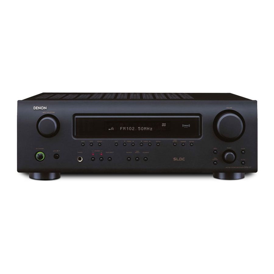
Denon DRA-37 Operating Instructions Manual
Am-fm stereo receiver
Hide thumbs
Also See for DRA-37:
- Operating instructions manual (30 pages) ,
- Brochure & specs (2 pages) ,
- Service manual (63 pages)
Table of Contents
Advertisement
Quick Links
Advertisement
Table of Contents

Related Manuals for Denon DRA-37


Summary of Contents for Denon DRA-37
- Page 1 AM-FM STEREO RECEIVER DRA-37 OPERATING INSTRUCTIONS...
-
Page 2: Safety Instructions
ENGLISH ¢SAFETY PRECAUTIONS CAUTION RISK OF ELECTRIC SHOCK DO NOT OPEN CAUTION: TO REDUCE THE RISK OF ELECTRIC SHOCK, DO NOT REMOVE COVER (OR BACK). NO USER-SERVICEABLE PARTS INSIDE. REFER SERVICING TO QUALIFIED SERVICE PERSONNEL. The lightning flash with arrowhead symbol, within an equilateral triangle, is intended to alert the user to the presence of uninsulated “dangerous voltage”... - Page 3 This product, when installed as indicated in the instructions contained in this manual, meets FCC requirements. Modification not expressly approved by DENON may void your authority, granted by the FCC, to use the product. 3. NOTE This product has been tested and found to comply with the limits for a Class B digital device, pursuant to Part 15 of the FCC Rules.
-
Page 4: Table Of Contents
ENGLISH Thank you for choosing the DENON DRA-37 AM-FM Stereo Receiver. This remarkable component has been engineered to provide outstanding high fidelity reproduction of your favorite music sources. As this product is provided with an immense array of features, we recommend that before you begin hookup and operation that you review the contents of this manual before proceeding. -
Page 5: Cautions On Installation
Note Wall About the remote control unit In addition to controlling the DRA-37, the attached remote control unit (RC-1053) can also be used to control the following products: q DENON component products w Component products other than DENON: •... -
Page 6: Part Names And Functions
ENGLISH Getting Started Part names and functions For details on the functions of these parts, refer to the pages given in parentheses ( ). Front panel @7 @6 @4 @ 3 i !0 ! 1 !2 Power operation button (ON/STANDBY) ··········································(10) Power indicator ·········································(10) Power switch ·······································(10, 16) Headphones jack (PHONES) ·····················(10) -
Page 7: Rear Panel
Getting Started Rear panel AUDIO OUT terminals·································(7) Power supply cord·······································(9) SUBWOOFER PRE OUT terminal ···············(6) VIDEO OUT terminals ·····························(6, 7) AUDIO IN terminals·································(6, 7) DOCK CONTROL jack ··································(9) PRE OUT terminals······································(9) XM terminal ·················································(8) VIDEO IN terminals ·································(6, 7) ANTENNA terminals ·······························(7, 8) Speaker terminals ·······································(6) REMOTE CONTROL jacks ···························(9) AC outlets·····················································(9) -
Page 8: Connections
ENGLISH Getting Started [ Rear ] Power buttons················(20) Number buttons (0 ~ 9, +10) ··········(12, 14, 17) BAND button ··················(12) Memory block buttons (A ~ G)···············(12) Input source selector buttons ····························(10) NOTE: • If buttons on the front or rear are pressed strongly, the button on the opposite side will be activated too. -
Page 9: Speaker Connections
Either tightly twist or terminate the the ventilation around the unit, switch off the core wires. power and contact a DENON service center. 3. Tighten by turning clockwise. Connecting banana plugs Turn clockwise to tighten, then insert the banana plug. -
Page 10: Connecting A Tv/Dbs Tuner
ENGLISH Connections Connecting a TV/DBS tuner Connecting a CD player Connecting a tape deck, CD recorder or MD recorder Connecting a VCR TV/DBS tuner VIDEO AUDIO OUT Connecting the antenna terminals An F-type FM antenna cable plug can be connected directly. CD player AUDIO OUT Direction of broadcasting station... -
Page 11: Connecting The Xm Terminal
Connection of AM antennas Connecting the XM terminal • DRA-37 is the XM Ready ® receiver. You can receive XM ® Satellite Radio by connecting to the XM Mini- 1. Push the lever. Tuner and Home Dock (includes home antenna, sold separately) and subscribing to the XM service. -
Page 12: Connecting The Ipod
When using an iPod, you must connect the Control Dock for iPod (ASD-1R, sold separately) and the DOCK CONTROL jack on the DRA-37 with a mini-jack and assign the iPod to any AUDIO terminal(s). The diagram below shows an example of connections for when the iPod is assigned to the CD-R/TAPE terminals. -
Page 13: Operation
INPUT SELECTOR MUTING <SPEAKER> VOLUME <POWER> <ON/STANDBY> <PHONES> [POWER ON] INPUT SELECTOR VOLUME MUTING [MODE SELECTOR 1] [MODE SELECTOR 2] INPUT SELECTOR About the button names in this explanation < > : Buttons on the main unit : Buttons on the remote control unit Button name only : Buttons on the main unit and remote control unit Operation... -
Page 14: Checking The Currently Playing Program Source, Etc
ENGLISH Operation <INPUT SELECTOR> <PRESET> VIDEO SELECT MEMORY STATUS DIMMER BAND SHIFT TUNING MODE PURE DIRECT <LOUDNESS> <SELECT> <ON/STANDBY> <TONE DEFEAT> <TONE CONTROL> [CHANNEL] SHIFT [FM/AM] DIMMER STATUS VIDEO SELECT PURE DIRECT BAND [MEMORY BLOCK] MODE MEMORY [TUNER] TUNING About the button names in this explanation <... -
Page 15: Listening To The Radio
This unit is equipped with a function for automatically searching for FM broadcast stations and storing them in the preset memory. < ON/STANDBY > Press and set the DRA-37’s power to the standby mode. < PRESET • > < ON/STANDBY >... -
Page 16: Xm Satellite Radio
ENGLISH Operation <INPUT SELECTOR> STATUS BAND TUNING <SELECT> XM RADIO MENU XM RADIO MENU ENTER [D H F G] STATUS [NUMBER] (0 ~ 9, +10) [SEARCH] BAND [TUNER] TUNING About the button names in this explanation < > : Buttons on the main unit : Buttons on the remote control unit Button name only : Buttons on the main unit and remote control unit... -
Page 17: Channel Selection
When using a Control Dock for iPod, it is possible to connect with the audio input terminal of the assigned function. ENTER Press • The optional standard Control Dock for iPod is DENON ASD-1R sold ENTER separately. • To assign to a different function after a function has already been assigned, switch to a function other than the one that is assigned then repeat the procedure. -
Page 18: Listening To Music
Information on the latest version of the software can be obtained on the Apple Computer website. • With the DRA-37 it is possible to display folder names and file names on the screen like titles. The DRA-37 can display up to 64 characters, consisting of numbers, capital letters and small letters. -
Page 19: Viewing Still Pictures And Videos (Only For Ipods Equipped With The Slideshow / Video Function)
About the memory functions ¢ Last function memory The various settings set when the DRA-37’s power is switched to standby are stored in the memory. When the power is turned back on, the settings made when the power was switched to standby are recalled. -
Page 20: Operating The Remote Control Unit
Setting the preset memory function • DENON and other makes of components can be operated by setting the preset memory. • This remote control unit can be used to operate components of... -
Page 21: Setting The Punch Through Function
Operating the remote control unit Setting the punch through function “Punch Through” is a function allowing you to operate on CD, DVD/VDP, TAPE/CD-R/MD or VCR components when in the TV or DBS/CABLE mode. By default, nothing is set. [MODE SELECTOR 1] to “A”. - Page 22 ENGLISH Operating the remote control unit ¢ Functions of buttons for the different devices [Front] Device operated CD player or iPod (Monitor) MODE SELECTOR 1 MODE SELECTOR 2 CD/iPod Power off – Power on Power on Preset – TV channels – CHANNEL –...
- Page 23 Tuning + TV volume + TUNING + Tuning – TV volume – TUNING – Default setting DENON HITACHI (Preset code) (111) (134) Special remarks Special remarks: It is only possible to set the preset memory for one device per mode. When a new code is preset, the previous code is automatically deleted.
-
Page 24: Troubleshooting
• Insert batteries properly. in reverse. • The set’s internal temperature has • Put the DRA-37 in a well-ventilated risen and the protection circuit has place. been activated. • Turn off the power, then wait for the set to fully cool off before turning the power back on. -
Page 25: Specifications
Specifications ¢ Audio section • Power amplifier Rated output: 50 W + 50 W (8 Ω/ohms, 20 Hz ~ 20 kHz with 0.08 % T.H.D.) Output terminals: A or B 4 ~ 16 Ω/ohms A + B 8 ~ 16 Ω/ohms •... - Page 26 ENGLISH ¢ List of preset codes Denon 014, *[111] Aiwa Hitachi 006, 011 Konka 012, 013 Magnavox Mitsubishi Panasonic Philips 005, 015, 016, 017 Pioneer 003, 008 Sanyo Sony 002, 019, 020 Toshiba 001, 021, 022 Zenith Denon 028, 029, 112...
- Page 27 Radix Technics Randex Teknika 007, 013, 019, 023, 058, 063, 064, 065, 073, 080, 082, 087 Toshiba Realistic 009, 021, 031, 033, 049, 053, 081, 087, 088, 091, Totevision 094, 097, 098 Unirech Ricoh Vecrtor Research Salora 033, 041 Victor Samsung 007, 011, 051, 059, 070, Video Concepts...
- Page 28 ENGLISH Philips Magnavox 005, 010, 017, 030, 033, 038, 050, 056, 071, 078, 079, 085, 089, 108, 109, Pioneer 110, 127, 131, 132, 145 Portland Marantz 015, 017, 071, 080 Price Club Matsui Proscan Memorex 014, 027, 045, 083, 118, Proton Pulsar Metz...
- Page 29 Teac Philips Technics Primestar Wards Proscan 048, 055, 056 Yamaha 048, 055, 056, 068 Zenith Realistic Sierra I Sierra II Denon Sierra III Philips Sony 049, 067 STS1 STS2 Denon STS3 Kenwood SRS4 Onkyo Technisat 077, 078, 079, 081, 082...
- Page 30 TOKYO, JAPAN www.denon.com Denon Brand Company, D&M Holdings Inc. Printed in China 00D 511 4541 104...