
Related Manuals for Universal Remote Control Complete Control MRF-260


Summary of Contents for Universal Remote Control Complete Control MRF-260
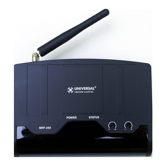
- Page 1 MRF-260 Installation Manual Optimizing Narrow Band Reception with Complete Control Remotes ™ COMPLETE COMPLETE CONTROL Universal Remote Control ®...
- Page 2 The information in this manual is copyright protected. No part of this man- ual may be copied or reproduced in any form without prior written consent from Universal Remote Control, Inc. UNIVERSAL REMOTE CONTROL, INC. SHALL NOT BE LIABLE FOR OPER- ATIONAL, TECHNICAL OR EDITORIAL ERRORS/OMISSIONS MADE IN THIS MANUAL.
-
Page 3: Table Of Contents
ABLE ONTENTS Introduction Features and Benefits Parts Guide Installation Testing Front Blaster Overload Disabling the Front Blaster - Step by Step via PC Controlling Four Identical Components/Zones Identical Components/Zones - Step by Step via PC 7 Programming For Multiple Equipment Locations USA Limited Warranty Statement Frequently Asked Questions Specifications... -
Page 4: Introduction
Addressing gives you the ability to control as many as 60 identical components throughout a house. To enable better range and reliabili- ty the MRF-260 is equipped with the Narrow Band RF reception (like the MRF-350), so is only compatible with other Narrow Band remotes. -
Page 5: Features And Benefits
Identical Zones of a Multi Zone Preamp/Matrix Switcher Each MRF-260 has four “addressable” IR Line Outputs. For example, you can control up to four identical TV’s with one MRF-260 or route volume commands for a specific zone to a particular zone IR input on a multi-zone preamp. -
Page 6: Installation
RF Interference (particularly devices with high speed microprocessors or hard drives). 3. Check that the address wheel on the rear of the MRF-260 is set to ID#0 (the interference “sniffing” position). Check that the arrow pointer in the center of the wheel is pointed to 0, the default “interference sniffing”... - Page 7 MRF-260 B TATION 5. Observe the Status LED of the MRF-260. If it is glowing or flick- ering you must relocate the MRF-260 to a location where the LED doesn’t flicker. If your installation location simply doesn’t offer you any choice...
-
Page 8: Testing
IR Line Output level. Note: Remember, the MRF-260 will NOT respond if you select IR line outputs 5 or 6. The MRF-260 has only four IR Line Outputs. 1. Connect an IR emitter to each IR output and run the emitter wire to the front panel of each component. -
Page 9: Front Blaster Overload
Front Blaster. This will limit the number of components your MRF- 260 can control to four. If you have more than four components you can purchase an additional MRF-260 or upgrade to an MRF- 350. Disabling the Front Blaster - Step by Step via PC Note: If you are programming a URC MX “addressable”... -
Page 10: Controlling Four Identical Components/Zones
Controlling Four Identical Components/Zones There are several considerations to take into account when you are installing an MRF-260 to control an array of identical components: 1. The RF ID# cannot be set to Code 0, the universal setting. You must use one of the fifteen unique IR Routing addresses. - Page 11 MRF-260 B TATION By looking at the Signal column, you can see that the factory default programming sets all of the devices to send both IR and RF commands. If you look at the column for Flashers, you can see that the default sends IR commands for all devices to ALL of the flash- ers.
- Page 12 TATION In the figure below, each device is set to a specific flasher. Note: Remember, the MRF-260 will only respond to selections 1 through 4. Step 5 - Make sure that the ID# is set on both the remote and on the wheel of the MRF-260.
-
Page 13: Programming For Multiple Equipment Locations
Programming For Multiple Equipment Locations You can operate up to 15 different equipment locations, each with an MRF-260 assigned a unique Receiver ID#. You program each of your remotes to talk to the equipment locations you want by assign- ing each of your devices to a receiver. First, you must add and... -
Page 14: Usa Limited Warranty Statement
MRF-260 B TATION USA Limited Warranty Statement Your Universal Remote Control, when delivered to you in new condition, is warranted against defects in materials or work- manship as follows: UNIVERSAL REMOTE CONTROL, INC. warrants this product against defects in material or workman- ship for a period of one (1) year and as set forth below. -
Page 15: Frequently Asked Questions
Second, set the RF ID# from 1-9 or A-F on both the remote control and the rear of the MRF-260. Third, check that the flasher level is set to the mini- mum necessary. Fourth, check that the emitter is facing the component. - Page 16 Such modifications could void the user's authority to operate the equipment. ™ COMPLETE COMPLETE CONTROL Universal Remote Control ® 500 Mamaroneck Avenue, Harrison, NY 10528 Phone: (914) 835-4484 Fax: (914) 835-4532 www.universalremote.com...