
Related Manuals for Universal Remote Control MRF-300/RFX150


Summary of Contents for Universal Remote Control MRF-300/RFX150
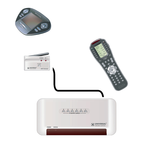
- Page 1 MRF-300/RFX150 INSTALLATION MANUAL Multi-Zone RF Base Station for the MX-3000, the Aurora , the Aeros , the Omega and the Osiris remote controls.
- Page 2 The information in this manual is copyright protected. No part of this manual may be copied or reproduced in any form without prior written consent from Universal Remote Control, Inc. UNIVERSAL REMOTE CONTROL, INC. SHALL NOT BE LIABLE FOR OPERATIONAL,TECHNI- CAL OR EDITORIAL ERRORS/OMISSIONS MADE IN THIS MANUAL.
-
Page 3: Table Of Contents
Introduction Features and Benefits Parts Guide Installation Front Blaster Overload Disabling the Front Blaster - Step by Step Controlling An Array of Identical Components or Zones Identical Components/Zones - Step by Step Programming For Multiple Equipment Locations Frequently Asked Questions Warranty Specifications ABLE... -
Page 4: Introduction
Introduction The MRF-300 base station is an “addressable” base station. It is only compati- ble with Universal Remote Control’s line of Custom Programmed Remotes with RF Addressing such as the MX-800, MX-650 Omega and the MX-350 Osiris. ability to control as many as 90 identical components throughout a house. -
Page 5: Features And Benefits
Features and Benefits Interference Rejection and Adjustable RF Range via RFX-150 The MRF-300 receives RF (radio frequency) signals via the RFX-150 RF Sensor. The RFX-150 displays RF interference via a bright RED LED, which flickers when interference is present. Simply relocate the RFX-150 out of the interference or reduce the range to eliminate interference via the RF Range adjust screw. -
Page 6: Installation
Installation Step 1 - Set the RF ID # rotary switch on the bottom of the MRF-300 to a VALID ID# (any address other than ID# 0). If you leave it set to ID# 0, the MRF-300 operates with some restrictions: a. - Page 7 Copper colored conductor is GROUND (Sleeve of the Plug). Silver colored conductor is IR DATA (Tip of the Plug). Daisy Chain Multiple MRF-300’s to One RFX-150 RF Sensor Use the cable with 3.5mm Stereo Mini plugs on both ends to daisy chain as many MRF-300’s as you need.
- Page 8 Step 4 - Connect the Power Supply to the MRF-300. Step 5 - Power on the entire Audio/Video System Test for RF Interference If you are restricted to a very small range of mounting locations and the LED flickers, reduce the range via the RF Range attenuator screw on the RFX-150. Step 6 - Mount the RFX-150 and adjust for Optimum Range Have someone press buttons on the remote control from the farthest distant operating position and adjust RF range screw and the angle of the RF-150...
- Page 9 MRF-300 B TATION Step 7 - Test RF Address Test that pressing a button on the remote control lights the STATUS LED of the MRF-300.The STATUS LED only lights when the correct RF address is received. Step 8 - Adjust IR Line Output Levels Adjust each of the IR Line Output levels for best operation.
-
Page 10: Front Blaster Overload
MRF-300 B TATION Front Blaster Overload A few models of audio/video components can be OVERLOADED by the Front Blaster. If you are having intermittent or inconsistent results with a particular component, try repositioning the MRF-300 and facing the Front Blaster in a different direction. -
Page 11: Controlling An Array Of Identical Components Or Zones
Controlling An Array of Identical Components or Zones There are several considerations to take into account when you are installing an MRF-300 to control an array of identical components: 1.The RF ID# cannot be set to Code 0, the universal setting.You must use one of the fifteen unique IR Routing addresses. - Page 12 MRF-300 B TATION Step 3 - Copy The Programmed Device In tree view, right click on the device you programmed. From the context menu that appears, select COPY. Step 4 - Paste The Programmed Device In tree view, right click on the first device that is NOT PROGRAMMED.
- Page 13 MRF-300 B TATION Click on the “cell” for the first Signal Column identical TV, by crossing the device row with the Signals col- umn. TV1 Device Row Select RF from the three options shown for EACH of the identical TV’s.You may leave the other components of the system set to IR & Step 7 - Adjust the Flashers For Each of the Identical Devices The RF Setup window enables you to adjust which Flashers output by the remote control for each device individually, by clicking on the intersection of a...
-
Page 14: Programming For Multiple Equipment Locations
Programming For Multiple Equipment Locations You can operate up to 15 different equipment locations, each with an MRF- 300 assigned a unique Receiver ID#. You program each of your remotes to talk to the equipment locations you want by assigning each of your devices to a receiver. -
Page 15: Frequently Asked Questions
The MRF-300 is covered against any manufacturers defects or workmanship for a period of one year from the date of purchase if purchased from an authorized Universal Remote Control dealer. Units purchased from online auc- tion sites or other unauthorized resellers have no warranty.This warranty does not cover the following items: -Damage from misuse, neglect, or acts of nature. - Page 16 The Complete Control Remote Control System 500 Mamaroneck Avenue, Harrison, NY 10528 Phone: (914) 835-4484 Fax: (914) 835-4532 www.universalremote.com...