Table of Contents

Related Manuals for FUTABA 6EXHP


Summary of Contents for FUTABA 6EXHP
- Page 1 INSTRUCTION MUNUAL for Futaba 6EXHP 6-channel, PCM/PPM(FM) selectable Radio control system for helicopter Futaba Corporation Technical updates available at: http://www.futaba-rc.com Entire Contents © Copyright 2005 1M23N12008 FUTZ8564 V1.0...
-
Page 2: Table Of Contents
“non-computer” radio. Although this is a beginner or sport system with the requirements of those flyers in mind, in order to make the best use of your Futaba 6EXHP and to operate it safely, you must carefully read all of the instructions. -
Page 3: Contents And Specifications
FM Dual Conversion 72 MHz low band (channels 11 - 35) receiver crystal . FUTL57** FM Dual Conversion 72 MHz high band (channels 36 - 60) receiver crystal . FUTL58** Note: Should you ever wish to change the transmitter frequency, the transmitter must be sent to the Futaba Service Center for retuning. -
Page 4: Introduction To The 6Exap System
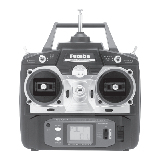
Futaba GY401/502/601 Gyro on gyro function of this transmitter. Transmitter controls The diagram and explanations briefly describe the functions of the Futaba T6EXHP transmitter. Full instructions on how to operate the controls are provided beginning on page 10. -
Page 5: Radio Installation
Gyro switch/Channel 5 - You can connect the sense adjust connector to the channel 5 of the receiver to operate the gyro which has two different sense. Also if you use Futaba GY401/502/601 Gyro, two different gyro senses setting on gyro function in this transmitter can be call by this switch. - Page 6 • After the servos are installed, operate each servo over its full travel and check that the pushrods and servo arms do not bind or contact each other. Also make sure the controls do not require excess force to operate. If there is an objectionable buzzing sound coming from a servo, there is probably too much resistance in the control.
-
Page 7: Receiver And Servo Connections
���� ����������� ����� ������ ����� CHARGING THE Ni-Cd BATTERIES The transmitter and receiver batteries included with your 6EXHP system are rechargeable, Ni-Cd (nickel-cadmium, pronounced Read the charging instructionscarefully. ni-kad) batteries. Ni-Cd batteries require special care and charging. NOTE: The batteries are supplied partially charged, but will require a full, overnight charge before the model may be flown. -
Page 8: Lcd And Programming Controls
If there is a noticeable drop in capacity the batteries should be replaced. Note: Charging your batteries with the included Futaba A/C battery charger is always safe. However, fast-charging with an aftermarket charger is acceptable as long as you know how to properly operate the charger. NEVER charge at a rate higher than 1,000 mAh (1 Amp). - Page 9 Model memory number and model name The Futaba T6EXHP stores model memories for six models. This means all the data (control throws, trims, end points, etc.) for up to six different models can be stored in the transmitter and activated at any time (depending upon which model you choose to fly that day).
-
Page 10: Programming The T6Ehap Radio
PROGRAMMING THE 6EXHP RADIO Anytime you wish to view or change any of the current settings in the transmitter, the programming mode must first be entered by, of course, turning on the power, then by pressing the “MODE” and “SELECT” keys simultaneously and holding them down for one second. -
Page 11: Puls Modulation Select Function
PULS Modulation select function The Modulation select function is used to select the PPM or PCM mode of transmission, to match the receiver being used (PPM-Pulse Position Modulation, also called FM for Frequency Modulation, and PCM-Pulse Code Modulation). To select modulation: 1. -
Page 12: D/R Dual Rate And Exponential Settings
Dual Rates / Exponential Settings The aileron, elevator and rudder dual rates on the 6EXHP are simultaneously activated by the dual rate switch. The amount of travel decrease for each control may be set between 0% and 100% of the values set for the end points (explained in End Point Adjustment on page 12). -
Page 13: Trim Trim Settings
correct throw. The pushrods should first be connected to the servo arms and control horns so that the correct, or near correct control surface throw will be achieved. THEN the EPAs may be used to make small changes in the servo throw until the desired control throw is achieved. The control throws should be set up so that the “end points”... -
Page 14: N-Th Normal Throttle Curve
N-TH Normal throttle curve function Used to set throttle curve for normal flight. 5-point throttle curve is utilized to best match the blade collective pitch to the engine RPM for consistent load on the engine. Throttle curve can be adjust from 0-100% each point. This normal throttle curve create basic curve for around hovering. -
Page 15: I-Pi Idle-Up Pitch Curve Function
3. Use SELECT key to select the desire curve point. Point 1 is shown initially which is throttles stick all the way downward (slow) position. Point 5 is throttles stick all the way upward (hi) position. 4. Push up or down DATA INPUT lever to set the servo position. 5. -
Page 16: Revo Pitch-Rudder Mixing Function
REVO Pitch-rudder mixing function This mix adds rudder in conjunction with pitch. This helps compensate for rotation of the helicopter caused by the increased engine torque. (Never use revo. mixing with a heading-hold/AVCS gyro which is in heading hold/AVCS mode. However, revo. mixing is still used when a heading-hold/AVCS gyro is in normal mode.) To set the REVO mixing: 1. - Page 17 • Heading-Hold SMM: 21st Century gyro technology. Computer chip technology. Expensive, easier set up, higher durability. Significant decrease in temperature sensitivity. Many include frame rate settings to allow faster response when using specialized digital servos. Examples: • GY401: Simpler set up. Ideal for learning aerobatics through 3D. •...
-
Page 18: Swsh Swashplate Types Selection & Swash Afr
SWSH Swashplate types selection & Swash AFR This function can chose from two swashplate types. Swash AFR can be set, if you chose 3-S type 1-S: Independent aileron, pitch and elevator servos linked to the swashplate. Most kits are 1-S type. ���... -
Page 19: Fs Fail Safe (Pcm Mode Only)
F/S Fail Safe (PCM mode only) The Fail Safe function is used to prescribe what the PCM receiver will do in the event radio interference is received, and doesn’t work FM(PPM) receivers. In this menu, you may select from one of two options of operation for each channel. The “NOR”(normal) setting holds the servo in its last commanded position, while the “F/S”(Fail Safe) function moves each servo to a predetermined position. -
Page 20: Flow Chart
FLOW CHART 6EXHP FUNCTIONS ����� ���� To change the Stick Mode, turn on the transmitter holding MODE and (Screen at Startup) SELECT keys down simultaneously. To enter or leave Programming Mode, press MODE and SELECT keys Use the DATA INPUT lever to display simultaneously for one second. -
Page 21: Othert6Exhp Functions
Then he will have immediate, full control. If connecting the 6EXHP to the T7CHP, T9CHP or 14MZ with the small, square “micro” trainer jack, use the “Micro to Micro” (MM-TC) trainer cord (FUTM4415). If connecting the 6EXHP to Futaba radios with the larger, round, “DIN” connector, use “Micro to DIN”... -
Page 22: Changing The Stick Mode
Changing the 6EXHP stick mode The transmitter may be operated in four different stick “modes” (1, 2, 3 & 4). The modes determine the functions that will be operated by control sticks. Currently, the transmitter is in “mode 2” and should be left in mode 2 unless you are an experienced flyer and have learned to fly in a different mode. -
Page 23: Flight Preparation
FLIGHT PREPARATION Flight preparation is to be done at the flying field. IMPORTANT: Your radio control system transmits a signal on a certain frequency. Be certain you know what the frequency is. This is expressed as a two-digit number (42, 56, etc.), and can be found on the container the transmitter came in and is also located on the transmitter and receiver. -
Page 24: Model Data Recording Sheets
MODEL DATA RECORDING SHEET (Make copies before using) Model name: Model No. 1• 2 • 3 • 4 • 5 • 6 ���� �������� �� � �� � �� � �� � �� � �� � ���� � � � �...