Table of Contents
Advertisement
Advertisement
Table of Contents

Related Manuals for EVGA 112-CK-NF72-K1


Summary of Contents for EVGA 112-CK-NF72-K1
-
Page 2: Parts Not In The Kit
Before You Begin… Parts NOT in the Kit This kit contains all the hardware necessary to install and connect your new EVGA nForce motherboard. However, it does not contain the following items that must be purchased separately to make the motherboard functional. - Page 3 • Supports hot plug • Up to ten USB 2.0 ports • Supports USB 2.0 protocol up to 480Mbps transmission rate Onboard Serial ATA II • 3Gb/s data transfer rate • Four Serial ATA II connectors • Support for RAID 0, RAID 1, RAID 0+1, and RAID 5, (RAID 0+1 and RAID 5 not supported on 610i) •...
-
Page 4: Hardware Installation
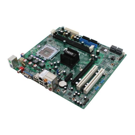
Hardware Installation This section will guide you through the installation of the motherboard. The topics covered in this section are: Preparing the motherboard • Installing the CPU • Installing the CPU fan • Installing the memory Installing the motherboard Connecting cables and setting switches Safety Instructions To reduce the risk of fire, electric shock, and injury, always follows basic safety precautions. - Page 5 EVGA nForce Motherboard The EVGA nForce motherboard with the 600 series MCP processor is a PCI Express motherboard with an onboard GeForce graphics card. Figure 1 shows the 7150/630i motherboard and Figures 2 shows the back panel connectors.
-
Page 6: Preparing The Motherboard
Preparing the Motherboard The motherboard shipped in the box does not contain a CPU or memory. You need to purchase a CPU, a CPU heat sink/fan assembly, and memory module(s) to complete this installation. -
Page 7: Installing The Cpu
Installing the CPU Be very careful when handling the CPU. Hold the processor only by the edges and do not touch the bottom of the processor. Use the following procedure to install the CPU onto the motherboard. 1. Unhook the socket lever by pushing down and away from the socket. -
Page 8: Pin Atx Power
Determine if it would be easier to make all the connections prior to this step or to secure the motherboard and then make all the connections. Use the following procedure to install the I/O shield and secure the motherboard into the chassis. -
Page 9: Front Panel Header
8-pin ATX 12V Power ( PWR2 , the 8-pin ATX 12V power connection, is used to provide power to the CPU. Align PWR2 the pins to the connector and press firmly until seated. It is strongly recommended that you use an 8-pin ATX 12V power supply; however a four-pin power supply may be used. -
Page 10: Usb Headers
PWRSW Attach the power button cable from the case to these two pins. Pressing the powerbutton on the front panel turns the system on off rather than using the power supply button. HD_LED Attach the hard disk drive indicator LED cable to these two pins. The HDD indicator LED indicates the activity status of the hard disks. -
Page 11: Pci Slots
9 in figure 1 Motherboard. Expansion Slots The EVGA nForce motherboard contains four expansion slots, two PCI Express slots and two PCI slots. For a full list of PCI Express x16 graphics card supported by this motherboard, go to www.evga.com/products/. -
Page 12: On-Board Led Codes
On-board LED Codes On-board LED Codes Code(hex) Name Description Reserved Jumps to E000 Execution of POST routines in E000 segment Early Superio Init Early Initialized the super IO Reserved Blank video Reset Video controller Reserved Init KBC Keyboard controller init KB test Test the Keyboard Reserved... - Page 13 Code(hex) Name Description Reserved Re-initial KB Load keyboard matrix Reserved HPM init Init Heuristic Power Management (HPM) Reserved Program chipset Early Programming of chipset registers Init PNP Init PNP Shadow VBIOS Shadow system/video BIOS Clock Gen Init onboard clock generator and sensor Setup BDA Setup BIOS DATA AREA (BDA) Reserved...
- Page 14 Code(hex) Name Description Reinit serial port Reinitialize Preboot agent serial port Reserved EISA Test If EISA non-volatile memory checksum is good, execute EISA initialization. If not, execute ISA tests and clear EISA mode flag. Reserved Size Memory Size base memory from 256K to 640K and extended memory above 1MB.
- Page 15 Code(hex) Name Description Initialize Floppy Initialize floppy disk drive Reserved FDD install Install FDD and setup BIOS data area parameters Reserved Reserved Reserved Initialize Hard Drive Initialize hard drive controller Reserved Detect HDD IDE device detection Reserved Detect serial ports Initialize serial ports Reserved Reserved...
- Page 16 Code(hex) Name Description Memory Presence Base memory detect Early Memory Board Initialization Extend Memory Turn on extended memory, cache initialization Special Display First display initialization Early Shadow Early shadow enable for fast boot Cache presence External caches Boot...