Table of Contents
Advertisement
Advertisement
Table of Contents

Related Manuals for EVGA X58 SLI3


Summary of Contents for EVGA X58 SLI3
-
Page 1: User's Guide
User’s Guide EVGA X58 SLI3 Motherboard... -
Page 2: Table Of Contents
Table of Contents User’s Guide ......................... 1 EVGA X58 SLI3 Motherboard ..................1 Before You Begin… ...................... 7 Parts NOT in the Kit ....................7 Intentions of the Kit ....................7 EVGA X58 SLI3 Motherboard ..................9 Motherboard Specifications..................9 Unpacking and Parts Descriptions ................11... - Page 3 8-pin ATX 12V Power (PW12) ............... 22 Connecting SATA Cables .................. 22 Connecting Internal Headers ................23 Front Panel Header ..................23 IEEE1394a (Firewire) ..................24 USB Headers ....................25 Audio ......................26 Fan Connections ....................27 Expansion Slots ....................28 PCI Slots ......................
- Page 4 CD-ROM Device Priority ..................41 First/Second/Third Boot Device ................. 41 Boot Other Device ....................42 Boot Up NumLock Status ................... 42 Security Option ....................42 Integrated Peripherals Menu .................. 43 OnChip PATA/SATA Device ................44 Onboard Device ....................45 USB Device Settings ..................46 Power Management Setup Menu ................
- Page 5 SmartFan Function ..................... 54 Frequency/Voltage Control Menu ................55 Memory Feature ....................56 Voltage Control....................58 CPU Feature ...................... 59 Installing Drivers and Software ..................62 Windows XP/Vista Driver Installation ..............62 Appendix A. POST Codes for the EVGA X58 SLI3 Motherboard .......63...
- Page 6 List of Figures Figure 1. EVGA X58 SLI3 Motherboard Layout ............ 13 Figure 2. Chassis Back Panel Connectors ............14 Figure 3. PW1 Motherboard Connector ..............21 Figure 4. BIOS CMOS Setup Utility Main Menu ............ 34 Figure 5. Standard CMOS Features Menu ............36 Figure 6.
-
Page 7: Before You Begin
Before You Begin… Thank you for purchasing the EVGA X58 SLI3 Motherboard. This board is designed to take the already excellent performance of the EVGA lineup and push it into the future by adding support for SATA 6Gbps and USB 3.0. - Page 8 When replacing a motherboard in a system case, you will need to reinstall an operating system even though the current Hard Disk Drive may already have an operating system.
-
Page 9: Evga X58 Sli3 Motherboard
EVGA X58 SLI3 Motherboard Thank you for purchasing the EVGA X58 SLI3 Motherboard. This motherboard offers enthusiast performance and when combined with two or three SLI-Ready NVIDIA ® GeForce graphics cards, you get innovative NVIDIA technology for enhanced ® ®... - Page 10 Six (6) onboard SATA II 300MBps data transfer rate Six SATA II connectors from south bridge with support for RAID 0, RAID 1, RAID 10 and RAID 5 Supports hot plug and NCQ (Native Command Queuing ) Two (2) SATA3 6Gbps onboard ports from Marvell 88SE9128 Chipset ...
-
Page 11: Unpacking And Parts Descriptions
Unpacking and Parts Descriptions Unpacking The EVGA X58 SLI3 Motherboard comes with all the necessary cables for adding a motherboard to a system case. If replacing a motherboard, you may not need many of these cables. All parts shipped in this kit are RoHS-compliant (lead-free) parts. -
Page 12: Evga X58 Sli3 Motherboard
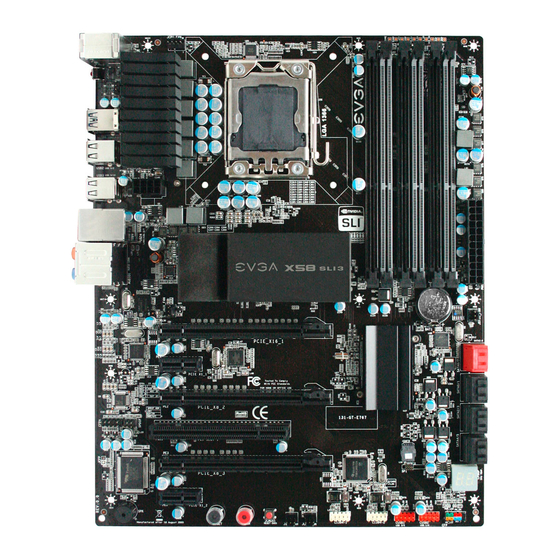
Contains drivers and software needed to setup the motherboard. EVGA X58 SLI3 Motherboard The EVGA X58 SLI3 Motherboard with the Intel X58 and ICH10R chipset is a PCI Express, SLI-ready motherboard. Figure 1 shows the motherboard and Figures 2 shows the back panel connectors. -
Page 13: Figure 1. Evga X58 Sli3 Motherboard Layout
Intel ICH10R Chipset 17. PC Speaker SATA II Connectors 18. PCI slots Debug LED Display - CPU Temperature 19. PCI Express 2.0 Slots Monitor 10. Front Panel Connector 20. PCI Express x1 Slot Figure 1. EVGA X58 SLI3 Motherboard Layout... -
Page 14: Figure 2. Chassis Back Panel Connectors
1. PS/2 Keyboard Port 2. USB 2.0 Ports (Eight) 3. Clear CMOS Button 4. USB 3.0 Ports (two) 5. LAN Port with LEDs to indicate status: Activity LED Status Description Speed/Link LED Status Description No data transmission Yellow 1000 Mbps data rate Blinking (Green) Data transmission Green... -
Page 15: Hardware Installation
Hardware Installation This section will guide you through the installation of the motherboard. The topics covered in this section are: Preparing the motherboard Installing the CPU Installing the CPU fan Installing the memory Installing the motherboard ... -
Page 16: Preparing The Motherboard
Preparing the Motherboard Installing the CPU Be very careful when handling the CPU. Hold the processor only by the edges and do not touch the bottom of the processor. Use the following procedure to install the CPU onto the motherboard: Unhook the socket lever by pushing down and away from the socket. -
Page 17: Installing The Cpu Fan
Align the notches in the processor with the notches on the socket. Lower the processor straight down into the socket with out tilting or sliding it into the socket Note: Make sure the CPU is fully seated and level in the socket. Align notches with notches on the CPU Close the load plate over the CPU and press down while you close and engage... -
Page 18: Installing System Memory (Dimms)
Installing System Memory (DIMMs) Your new motherboard has six 240-pin slots for DDR3 memory. These slots support 1GB, 2GB, 4GB DDR3 DIMMs. There must be at least one memory bank populated to ensure normal operation. Use the following the recommendations for installing memory. -
Page 19: Installing The Motherboard
Installing the Motherboard The sequence of installing the motherboard into a system case depends on the chassis you are using and if you are replacing an existing motherboard or working with an empty system case. Determine if it would be easier to make all the connections prior to this step or to secure the motherboard and then make all the connections. -
Page 20: Securing The Motherboard Into A System Case
Securing the Motherboard into a System Case Most system cases have a base with mounting studs or spacers to allow the motherboard to be secured to the chassis and help to prevent short circuits. If there are studs that do not align with a mounting hole on the motherboard, it is recommended that you remove that stud to prevent the possibility of a short circuit. -
Page 21: 24-Pin Atx Power (Pw1)
USB 2.0 24-pin ATX Power (PW1) is the main power supply connector located along the edge of the board next to the DIMM slots. Make sure that the power supply cable and pins are properly aligned with the connector on the motherboard. Firmly plug the power supply cable into the connector and make sure it is secure. -
Page 22: 8-Pin Atx 12V Power (Pw12)
8-pin ATX 12V Power ( PW12 PW12, the 8-pin ATX 12V power connection, is used to provide power to the CPU. Align the pins to the connector and press firmly until seated. Connecting SATA Cables The SATA II connector is used to connect the SATA II device to the motherboard. These connectors support the thin SATA II cables for primary storage devices. -
Page 23: Connecting Internal Headers
Connecting Internal Headers Front Panel Header The front panel header on this motherboard is one connector used to connect the following four cables. (see Table 2 for pin definitions): PWRLED Attach the front panel power LED cable to these two pins of the connector. -
Page 24: Ieee1394A (Firewire)
IEEE1394a (Firewire) This motherboard has two (2) IEEE 1394a onboard headers. Alternatively, you can also connect these to your system case (if applicable) Secure the bracket to either the front or rear panel of the system case (not all system cases are equipped with the front panel option). Connect the end of the cable(s) to the IEEE1394a headers on the motherboard. -
Page 25: Usb Headers
USB Headers This motherboard contains eight (8) USB 2.0 ports that are exposed on the rear panel of the chassis (Figure 2). The motherboard also contains two 10-pin internal header connectors onboard that can be used to connect an optional external bracket containing four USB 2.0 ports. -
Page 26: Audio
Audio The audio connector supports HD audio standard and provides two kinds of audio output choices: the Front Audio, the Rear Audio. The front Audio supports re-tasking function. Table 5. Front Audio Connector Connector Signal PORT1_L Front Audio Connector AUD_GND PORT1_R PRECENCE_J PORT2_R... -
Page 27: Fan Connections
Fan Connections There are six fan connections on the motherboard. The fan speed can be detected and viewed in the section of the CMOS Setup. The PC Health Status fans are automatically turned off after the system enters S3, S4 and S5 mode. System Fan Sense +12V... -
Page 28: Expansion Slots
Expansion Slots The EVGA X58 SLI3 Motherboard contains six (6) expansion slots, five (5) PCI Express slots and one (1) PCI slots. For a full list of PCI Express graphic cards supported by this motherboard, visit: www.EVGA.com/Products Slot Listing 1 –... -
Page 29: Pci Slots
PCI Slots The PCI slot supports many expansion cards such as a LAN card, USB card, SCSI card and other cards that comply with PCI specifications. When installing a card into the PCI slot, be sure that it is fully seated. Secure the card’s metal bracket to the chassis back panel with the screw used to hold the blank cover. -
Page 30: Onboard Buttons
Onboard Buttons These onboard buttons include RESET, POWER and Clear CMOS. These functions allow you to easily reset the system, turn on/off the system, or clear the CMOS. Clear CMOS Button The motherboard uses the CMOS RAM to store all the set parameters. The CMOS can be cleared by pressing the Clear CMOS button either onboard or on the external I/O Panel. -
Page 31: Post Port Debug Led And Led Status Indicators
Post Port Debug LED and LED Status Indicators Post Port Debug LED Provides two-digit POST codes to show why the system may be failing to boot. It is useful during troubleshooting situations. This Debug LED will also display current CPU temperatures after the system has fully booted into the Operating System. -
Page 32: Configuring The Bios
Configuring the BIOS This section discusses how to change the system settings through the BIOS Setup menus. Descriptions of the BIOS parameters are also provided. This section includes the following information: Enter BIOS Setup Main Menu Standard CMOS Features ... -
Page 33: Enter Bios Setup
Enter BIOS Setup The BIOS is the communication bridge between hardware and software. Correctly setting the BIOS parameters is critical to maintain optimal system performance. Use the following procedure to verify/change BIOS settings. Power on the computer. Press the key when the following message briefly displays at the bottom of the screen during the Power On Self Test (POST). -
Page 34: Figure 4. Bios Cmos Setup Utility Main Menu
Phoenix – AwardBIOS CMOS Setup Utility Standard CMOS Features Frequency/Voltage Control Load Defaults Advanced BIOS Features Integrated Peripherals Set Supervisor Password Power Management Setup Set User Password PnP/PCI Configurations Save & Exit Setup PC Health Status Exit Without Saving Esc : Quit... - Page 35 Frequency/Voltage Control Use this menu to optimize system performance and configure clocks, voltages, memory timings, and more. The following items on the CMOS Setup Utility main menu are commands rather than submenus: Load Fail-Safe Defaults Load Fail-Safe defaults system settings. Load Optimized Defaults ...
-
Page 36: Standard Cmos Features Menu
Standard CMOS Features Menu The Standard CMOS Features menu is used to configure the standard CMOS information, such as the date, time, HDD model, and so on. Use the Page Up keys to scroll through the options or press to display the Page Down Enter sub-menu. -
Page 37: Date And Time
Date and Time Using the arrow keys, position the cursor over the month, day, and year. Use keys to scroll through dates and times. Note that Page Up Page Down the weekday (Sun through Sat) cannot be changed. This field changes to correspond to the date you enter. - Page 38 Press to auto-detect IDE and SATA channels in the system. Once the Enter channel is detected, the values for Capacity, Cylinder, Heads, Precomp, Landing Zone, and Sector are automatically filled in. None There is no HDD installed or set. Auto ...
-
Page 39: Halt On
Halt On determines whether or not the computer stops if an error is detected Halt On during power on. Use the keys to scroll through the Page Up Page Down sub-menu. Use the arrow keys options or press to display the Enter Halt On to position the selector in the option you choose. -
Page 40: Advanced Bios Features
Advanced BIOS Features Access the Advanced BIOS Features menu from the CMOS Utility Setup screen. Use the keys to scroll through the options or Page Up Page Down to display the sub-menu. Use the arrow keys to position the press Enter selector in the option you choose. -
Page 41: Hard Disk Boot Priority
Hard Disk Boot Priority Use this option to select the priority for HDD startup. Press to see the Enter list of bootable devices in your system. Use the arrow keys to go to the various devices. Then use the keys to move the device priority up or –... -
Page 42: Boot Other Device
Boot Other Device With the option set to , the system boots from some other device if the Enable first/second/third boot devices fail. Boot Up NumLock Status This option allows you to select the power-on state of . Select NumLock activate the keyboard when the system is started. -
Page 43: Integrated Peripherals Menu
Integrated Peripherals Menu Select from the CMOS Setup Utility menu and Integrated Peripherals press to display the Integrated Peripherals menu. Enter Phoenix – AwardBIOS CMOS Setup Utility Integrated Peripherals Onboard PATA/SATA Device [Press Enter] Item Help Onboard Device [Press Enter] ... -
Page 44: Onchip Pata/Sata Device
OnChip PATA/SATA Device Press to display the OnChip PATA/SATA Device menu. Enter SATA Mode [IDE] LEGACY Mode Support [Disabled] SATA 3.0 Storage Controlle [Enabled] SATA Mode This is allows you set the onboard Serial SATA mode. IDE: Use the SATA hard disk drivers as Parallel ATA storage devices. ... -
Page 45: Onboard Device
Onboard Device Press to display the Onboard Device menu. Enter PE5 Slot (PCIE x1) [Auto] Realtek GigaLan (LAN1) [Auto] PE4 Slot (PCIE x1) [Auto] Realtek Lan PXE Boot ROM [Disabled] TI 1394 Setting [Enabled] High Definition Audio [Enabled] P80 Show CPU Temp. [Enabled] PE5 Slot (PCIE x1) ... -
Page 46: Usb Device Settings
USB Device Settings Press to display the USB Device Settings menu. Enter USB 3.0 Controller [Enabled] USB 1.0 Controller [Enabled] USB 2.0 Controller [Enabled] USB Operation Mode [High Speed] USB Keyboard Function [Enabled] USB Mouse Function [Enabled] USB Storage Function [Enabled] *** USB Mass Storage Device Boot Setting *** USB 3.0 Controller... -
Page 47: Power Management Setup Menu
Power Management Setup Menu Select from the CMOS Setup Utility menu and Power Management Setup press to display the Power Management Setup menu. Enter ACPI function [Enabled] Item Help APCI Suspend Type [S3(STR)] Run VGABIOS if S3 Resume [Auto] Main Level Soft-Off by PWR-BTTN [Instant-Off]... -
Page 48: Acpi Suspend Type
ACPI Suspend Type This function on the Power Management Setup menu allows you to select an ACPI Suspend Type. Types to select from are , and [S1&S3] [S1(POS)] [S3(STR)] Run VGABIOS if S3 Resume This function on the Power Management Setup menu allows you determines whether or not to enable the system to run the VGA BIOS when resuming from S3(STR) or S1&S3. -
Page 49: Power On Function
Day of Month Alarm [ 0] Time (hh:mm:ss) Alarm [0 : 0 : 0] To enter a day or time, use the keys to scroll through Page Up Page Down numbers or enter the number using the keyboard number or the keys. -
Page 50: Pnp/Pci Configuration Menu
PnP/PCI Configuration Menu Select from the CMOS Setup Utility menu and press PnP/PCI Configuration to display the PnP/PCI Configuration menu. Enter Phoenix – AwardBIOS CMOS Setup Utility PnP/PCI Configuration Init Display First [PCI Slot] Item Help Reset Configuration [Disabled] Resources Controlled By [Auto(ESCD)] ... -
Page 51: Reset Configuration
Reset Configuration This function on the PnP/PCI Configuration menu allows you to enable or disable the resetting of Extended System Configuration Data (ESCD) when you exit Setup. Set this to [Enabled] if you have installed a new add-on and the system reconfiguration has caused a serious conflict that prevents the OS from booting. -
Page 52: Pci/Vga Palette Snoop
Use Legacy ISA for devices compliant with the original PC AT Bus specification. Use PCI/ISA PnP for devices compliant with the plug-and-play standard, whether designed for PCI or ISA Bus architecture. PCI/VGA Palette Snoop This item is designed to overcome problems that may be caused by some nonstandard VGA cards.. -
Page 53: Pc Health Status Menu
PC Health Status Menu Select from the CMOS Setup Utility menu and press Enter PC Health Status to display the PC Health Status menu. Phoenix – AwardBIOS CMOS Setup Utility PC Health Status SmartFan Function [Press Enter] Item Help VCC 3.3V 3.28V CPU Vcore... -
Page 54: Smartfan Function
SmartFan Function Press to display the SmartFan Function menu. Enter CPU Fan Type [PWM Fan (4pin)] CPU Speed Control [SmartFan] Manual Fan Speed, % If temp > 100ºC, Set Fan Speed 100% If temp < 30ºC, Set Fan Speed Power Speed Control [SmartFan] Manual Fan Speed, % If temp >... -
Page 55: Frequency/Voltage Control Menu
EVGA X58 SLI3 Motherboard Frequency/Voltage Control Menu Select from the CMOS Setup Utility menu and Frequency/Voltage Control press to display the Frequency/Voltage Control menu. Enter Phoenix – AwardBIOS CMOS Setup Utility Frequency/Voltage Control Dummy O.C. [Disabled] Item Help Extreme Cooling [Disabled] ... -
Page 56: Memory Feature
Memory Feature Select from the Frequency/Voltage Control menu and press Memory Feature to display the Memory Feature menu. Enter Phoenix – AwardBIOS CMOS Setup Utility Memory Feature Memory SPD [Standard] Item Help Memory Control Setting [Disabled] Memory Frequency [Auto] Target memory Frequency 1067 Mhz ... - Page 57 Rank Interleave Setting This function is allows you to select the Rank Interleave Setting. The options are 1 way, 2 way and 4 way. tCL Setting This function is set the CAS latency. The options are 0 through 18. tRCD Setting ...
-
Page 58: Voltage Control
F7:Optimized Defaults Figure 13. Voltage Control EVGA VDroop Control EVGA VDroop control is a safety measure by motherboards to protect the CPU. Select [With VDroop] to calibrate CPU VDroop or select [Without VDroop] to disable this function CPU VCore ... -
Page 59: Cpu Feature
CPU PLL VCore Use the Page Up and Page Down to scroll through the voltages or select [Auto] to automatically set the voltage level for the CPU PLL Voltage. QPI PLL VCore Use the Page Up and Page Down to scroll through the voltages or select [Auto] to automatically set the voltage level for the QPI PLL Voltage. - Page 60 Phoenix – AwardBIOS CMOS Setup Utility CPU Feature Intel SpeedStep [Enabled] Item Help Turbo Mode Function [Enabled] CxE Function [Auto] Main Level Execute Disable Bit [Enabled] Virtualization Technology [Enabled] ***** Logical Processor Setting ***** Intel HT Technology [Enabled] Active Processor Cores [All] ***** QPI Controller Setting ***** QPI Controller Setting...
- Page 61 Virtualization Technology When this function is enabled, it allows a VMM to utilize the additional hardware capabilities provided by Intel Virtualization Technology. Logical Processor Setting Intel HT Technology This function is allows you to enable the Intel HT Technology. The options are Enabled and Disabled.
-
Page 62: Installing Drivers And Software
Windows XP 32bit and 64bit and is Vista-capable. The kit comes with a CD that contains utilities, drivers, and additional software. The CD that has been shipped with the EVGA X58 SLI3 Motherboard contains the following software and drivers: Chipset Drivers ... -
Page 63: Appendix A. Post Codes For The Evga X58 Sli3 Motherboard
Appendix A. POST Codes for the EVGA X58 SLI3 Motherboard This section provides the Award POST Codes (Table 6) for the EVGA X58 SLI3 Motherboard during system boot up. The POST Codes are displayed on the Debug LED readout located directly onboard the motherboard. - Page 64 Award POST Codes Code Name Description Reserved CheckSum Check the integrity of the ROM,BIOS and message Check Reserved Autodetect Check Flash type and copy flash write/erase routines EEPROM Reserved Test CMOS Test and Reset CMOS Reserved Load Chipset Load Chipset Defaults Reserved Init Clock Initialize onboard clock generator...
- Page 65 Award POST Codes Code Name Description Setup BDA Setup BIOS DATA AREA (BDA) Reserved CPU Speed Chipset programming and CPU Speed detect detect Reserved Init video Initialize Video Reserved Video memory Test Video Memory and display Logos test Reserved Reserved Reserved Reserved Reserved...
- Page 66 Award POST Codes Code Name Description Test 8259-2 Verify 8259 Channel 2 masked interrupts by Mask alternately turning off and on the interrupt lines. Reserved Reserved Test Stuck Turn off interrupts then verify no 8259's interrupt Interrupt mask register is on. Test 8259 Force an interrupt and verify the interrupt occurred.
- Page 67 Award POST Codes Code Name Description Display Reserved Setup Virus Setup virus protect according to Protect Setup Reserved Awdflash Load If required, will auto load Awdflash.exe in POST Reserved Onboard I/O Init Initializing onboard superIO Reserved Reserved Setup enable Display setup message and enable setup functions Reserved Reserved Initialize...
- Page 68 Award POST Codes Code Name Description Initialize Hard Initialize hard drive controller Drive Reserved Detect HDD IDE device detection Reserved Detect serial Initialize serial ports. ports Reserved Reserved Detect parallel Initialize parallel ports. ports Reserved HDD Write HDD check for write protection Protect Reserved Reserved...
- Page 69 Award POST Codes Code Name Description Reserved Enable Parity Enable Parity Check Check Reserved IRQ12 Enable Enable IRQ12 if mouse present Reserved Reserved Reserved Boot Medium Detect and store boot partition head and cylinders Read values in RAM Final Init Final init for last micro details before boot NumLock Set NumLock status according to Setup...
-
Page 70: Evga Glossary Of Terms
EVGA Glossary of Terms ACPI - Advanced Configuration and Power Interface AFR – Alternate Frame Rendering APIC - Advanced Programmable Interrupt Controller BIOS - Basic Input Output System CD-ROM - Compact Disc Read-Only Memory CMOS - Complementary Metal-Oxide Semiconductor CPU – Central Processing Unit D-ICE –... - Page 71 IEEE - Institute of Electrical and Electronics Engineers IGP - Integrated Graphics Processors IRQ - Interrupt Request JBOD - Just a Bunch of Disks JEDEC - Joint Electron Device Engineering Council LAN - Local Area Network LCD - Liquid Crystal Display LGA –...
- Page 72 SLI - Scalable Link Interface SPD - Serial Presence Detect SPDIF - Sony/Philips Digital Interconnect Format SPP - System Platform Processors TCP/IP - Transmission Control Protocol/Internet Protocol USB - Universal Serial Bus VDroop - V-core Voltage Drop VGA - Video Graphics Array...