
Related Manuals for Supero AOC-1UIPMI-B


Summary of Contents for Supero AOC-1UIPMI-B
- Page 1 UPER ® AOC-1UIPMI-B AOC-IPMI20-E AOC-LPIPMI-LANG AOC-1UIPMI-LANG USER’S MANUAL Revision 1.0a...
- Page 2 Clara County in the State of California, USA. The State of California, County of Santa Clara shall be the exclusive venue for the resolution of any such disputes. Supermicro's total liability for all claims will not exceed the price paid for the hardware product.
-
Page 3: Manual Organization
About This Manual This manual is written for system integrators, PC technicians and knowledgeable PC users who intend to integrate Supermicro’s unique IPMI 2.0 Management Utility card into their systems. It provides detailed information for the application and use of the AOC-1UIPMI-B, AOC-IPMI20-E, AOC-1UIPMI-LANG and AOC-LPIPMI-LANG add-on cards that supports remote access for system monitoring, diagnosis and management. -
Page 4: Table Of Contents
Conventions Used in the Manual: ................. iii Chapter 1 Introduction Overview ......................1-1 Features of IPMI Version 2.0 Software ............1-1 Contacting Supermicro ..................1-2 Returning Merchandise for Service ..............1-3 Checklist ......................1-4 Hardware Product Features ................1-4 Chapter 2 Technical Specifications and Hardware Installation Configuration .................... - Page 5 Table of Contents Delete System ....................3-15 Modify Group ....................3-15 Delete Group ....................3-16 Join a Group ....................3-16 Disjoin a Group .................... 3-16 Selecting an IPMI View Management Session ..........3-16 Closing IPMI View Management Session ............ 3-16 Login ......................
- Page 6 AOC-IPMI User’s Manual 3-11 Text Console Redirection (SOL, Serial Over LAN) ........3-30 SOL for IPMI 2.0 ..................3-30 For Windows 2003: ..................3-31 For Linux: ...................... 3-31 Chapter 4 Troubleshooting Frequently Asked Questions ................4-1 Contacting Supermicro’s Technical Support ........... 4-1...
-
Page 7: Chapter 1 Introduction
Chapter 1 Introduction Overview This user's manual covers the AOC-1UIPMI-B, AOC-IPMI20-E, AOC-1UIPMI-LANG and AOC-LPIPMI-LANG add-on cards. These cards are highly efficient, highly com- patible and easy-to-use IPMI cards. They allow the user to take advantage of the BMC, a baseboard management controller installed on a server motherboard and... -
Page 8: Contacting Supermicro
Super Micro Computer, Inc. 980 Rock Ave. San Jose, CA 95131 U.S.A. Tel: +1 (408) 503-8000 Fax: +1 (408) 503-8008 Email: marketing@supermicro.com (General Information) support@supermicro.com (Technical Support) Web Site: www.supermicro.com Europe Address: Super Micro Computer B.V. Het Sterrenbeeld 28, 5215 ML... -
Page 9: Returning Merchandise For Service
For faster service, RMA authorizations may be requested online (http://www. supermicro.com/support/rma/). Whenever possible, repack the add-on card in the original Supermicro box, using the original packaging materials. If these are no longer available, be sure to pack the add-on card in an anti-static bag and inside the box. Make sure that there is enough packaging material surrounding the add-on card so that it does not become damaged during shipping. -
Page 10: Checklist
AOC-IPMI User’s Manual Checklist If your shipping package came with missing or damaged parts, please contact Supermicro’s technical support. Please refer to the following checklist when con- tacting us. • AOC-1UIPMI-B, AOC-IPMI20-E, AOC-1UIPMI-LANG or AOC-LPIPMI-LANG. • CDR IPMI: One installation CD. - Page 11 Chapter 1: Introduction • Control through OS: • Shutdown • Reboot • Power cycle • Control directly through buttons on chassis: • Reset • Power down • Power up • Power cycle • Supports SNMP trap (multiple destinations) • Console Redirection (text only) through LAN...
-
Page 12: Chapter 2 Technical Specifications And Hardware Installation
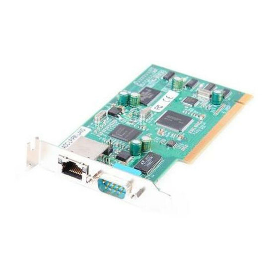
Chapter 2: Installation Chapter 2 Technical Specifications and Hardware Installation Configuration The AOC-1UIPMI-B, AOC-IPMI20-E and AOC-LPIPMI-LANG add-on cards share LAN1 on the motherboard for IPMI traffic. Components AOC-1UIPMI-B Figure 1-1: AOC-1UIPMI-B JPCIE1 Figure 1-2: AOC-1UIPMI-B Front Layout AOC-1UIPMI-B Front Component and LED Descriptions #1. - Page 13 AOC-IPMI User’s Manual Figure 1-3: AOC-1UIPMI-B Rear Layout #1: BMC Chip...
-
Page 14: Aoc-1Uipmi-Lang
Chapter 2: Installation AOC-1UIPMI-LANG Figure 1-4: AOC-1UIPMI-LANG Figure 1-5: AOC-1UIPMI-LANG Layout AOC-1UIPMI-LANG Front Component and LED Descriptions #1. NIC Connector... -
Page 15: Aoc-Ipmi20-E
AOC-IPMI User’s Manual AOC-IPMI20-E Figure 1-6: AOC-IPMI20-E D10 D9 Figure 1-7: AOC-IPMI20-E Layout AOC-IPMI20-E Front Component and LED Descriptions #1. BMC Chip #2. Activity LED #3. Processor Reset LED... -
Page 16: Aoc-Lpipmi-Lang
Chapter 2: Installation AOC-LPIPMI-LANG Figure 1-8: AOC-LPIPMI-LANG Figure 1-9: AOC-LPIPMI-LANG Layout AOC-LPIPMI-LANG Front Component and LED Descriptions #1. BMC Chip #2. Activity LED #3. Processor Reset LED #4. NIC Connector... -
Page 17: Led Descriptions
The LED will blink for a fraction of a second when the BMC card is reset. You can see this LED flash when you plug the power cable in. Block Diagram UART Interface (SOL) Supermicro Featured GPIO RENESAS H8S LPC Interface SMDATA SMCLK SMALT#... -
Page 18: Installation
Installation Safety Guidelines To avoid personal injury and property damage please carefully follow all the safety steps listed below when installing the AOC-1UIPMI-B, AOC-IPMI20-E or AOC- LPIPMI-LANG add-on card into your system. ESD Safety Guidelines Electrostatic Discharge (ESD) can damage electronic components. To prevent dam- age to your system, it is important to handle it very carefully. - Page 19 AOC-IPMI User’s Manual Notes...
-
Page 20: Chapter 3 Software Application And Usage
LAN. The necessary utilities for the access and configuration of the add-on card are included on the Supermicro bootable CDs that came with your card. This section provides information on the configuration and the access of the IPMI card on the network. -
Page 21: Bmc Firmware Update
AOC-IMPI User’s Manual BMC Firmware Update Shut down the system and unplug the AC power cord. Insert the BMC card. A: If you use a supplied CD-ROM, follow the steps below: • Turn on your computer and put the IPMI CD into the CD-ROM drive. •... - Page 22 Chapter 3: Troubleshooting Step 2. Select the firmware upgrade tool version. RMCP (Remote Management Control Protocol) is a request-response protocol that allows the transfer of IPMI messages and other types of payloads to an IPMI-based BMC over IP. RMCP+ is an enhanced protocol that offers enhanced authentication, encryption, discovery, and the ability to carry additional types of traffic payloads.
- Page 23 AOC-IMPI User’s Manual Step 1. Place the CD in your computer (Windows should have been installed). If you have autorun enabled, you will see the following screen (see below). Otherwise double click on the CD-ROM icon in your ‘My computer’ window, and it will bring up the screen below.
-
Page 24: Ipmicfg Usage
Note: When plugging or unplugging a BMC card, you must first unplug the AC power cord. IPMICFG usage: IPMICFG Version 1.07 (Build 080209) Copyright 2007 SuperMicro Computer Inc. Usage: IPMICFG params (Example: IPMICFG -m 192.168.1.123) Show IP and MAC -m IP Set IP (format: ###.###.###.###) -
Page 25: Software Installation Procedures
ASF (Alert Standard Forum) protocol. If the managed system is protected by a firewall, UDP port 623 must be opened. In Supermicro’s IPMI solution, a BMC shares the LAN1 NIC on the mainboard. The NIC will re-route the IPMI packet to the BMC instead of forwarding it to the upper layer network protocol stacks (as other protocol packets do). - Page 26 Chapter 3: Troubleshooting a) Installing the IPMIView: i) For Windows: Select “Install IPMIView” from auto-run windows to install IPMIView. You may also select IPMIView20setupwin32.exe” in the “IPMI SOLUTION/Windows/ Administrator” directory. ii) For Linux: Select “IPMIView20setuplinux.bin” in the “IPMI SOLUTION/Linux/Ad- ministrator” directory. Figure 1: Step 1 Figure 2: Step 2...
- Page 27 AOC-IMPI User’s Manual Figure 3: Step 3 Figure 4: Step 4...
- Page 28 Chapter 3: Troubleshooting Figure 5: Step 5 Figure 6: Step 6...
-
Page 29: System Management
Status Area: Shows messages regarding current status. • System View Sessions: IPMI View may manage up to 20 systems at the same time. The current managed system is indicated in the System View window. • Logo: Press Logo to visit Supermicro’s web site. 3-10... - Page 30 Chapter 3: Troubleshooting Figure 2-2 Step 1. As shown in Figure 2-3, click “File>New…>System” to add a new system to IPMI View. An “Add a new system…” dialog box will pop up as shown in Figure 2-4. Figure 2-3 3-11...
- Page 31 AOC-IMPI User’s Manual Figure 2-4 Step 2. As shown in Figure 2-4, in the “Add a new system” dialog box, type in the desired System Name for the managed system and the correct IP address, as well as a description. Then click OK. Figure 2-5 Step 3.
- Page 32 Chapter 3: Troubleshooting Figure 2-6 Step 4. As shown in Figure 2-6, IPMI View includes a function that allows the user to collect candidate system information in order to build their information into a System List (see Figure 2-6). User may specify the IP range to search any possible system that has either IPMI 1.5 or IPMI 2.0 capability.
-
Page 33: Reload Configuration
AOC-IMPI User’s Manual Figure 2-7 Step 5. As shown in Figure 2-7, Reload Configuration From the pull-down menu, click “File>Reload Configuration” to load the previous saved configuration. Save Configuration From the pull-down menu, click “File>Save Configuration” to save the current IPMI View configuration. -
Page 34: Modify System
Chapter 3: Troubleshooting Figure 2-8 Step 6. As shown in Figure 2-8, Modify System Select a system in the System Window you want to modify and then click “Edit>Modify…>System” from the pull-down menu shown in Figure 2-7 to modify You can also right click on a system in the System Window, and then select “Modify” in the pop-up menu to modify it. -
Page 35: Delete Group
AOC-IMPI User’s Manual Delete Group Select a group in the Group Window you want to delete and then click “Edit>Delete… >Group” from the pull-down menu shown in Figure 2-7 to delete it. You can also right click on a group in the Group Window, and then select ”Delete” in the pop-up menu to delete it. -
Page 36: Login
Chapter 3: Troubleshooting Or - right click on the system in the System Window you want to close and select “Close Session” in the pop-up menu to close it. When closing a session, a session will not be closed until 1) replies have been received for all outstanding packets or 2) all outstanding packets have timed out. - Page 37 AOC-IMPI User’s Manual Figure 3-0 Note: The default Login ID is “ADMIN”,,which has the default password of “ADMIN”. Both the Login ID and Password are case-sensitive. In the IPMI design, an MD5 algorithm will encrypt the password when it is transmit- ted through the network.
-
Page 38: Ipm Device
Chapter 3: Troubleshooting Figure 3-1 Note: In order to reduce overhead on the managed system, all pages will not refresh automatically. The user must refresh manually as needed. IPM Device Figure 3-2 3-19... -
Page 39: Device Information
AOC-IMPI User’s Manual Clicking the IPM Device tab of the IPMI View management session in the Viewing Window (shown in Figure 3-2) will display some information and functions of the system’s BMC firmware. Device Information This shows the revision levels of the BMC and IPMI firmware. ACPI System Power State This shows the managed system’s power state. -
Page 40: Chassis Power Control (Administrator And Operator Only)
Chapter 3: Troubleshooting The Power Cycle function will shut down the managed system for a few seconds and then power up the system. Graceful power control will send an event to the System Event Log (next section). If no more memory space is left for the incoming event, graceful power control will not function. -
Page 41: System Event Log
AOC-IMPI User’s Manual System Event Log Figure 3-3 Clicking on the Event Log tab of the IPMI View management session in the Viewing Window (shown in Figure 3-3) gives you detailed information on the System Event Log for the BMC. It shows the System Event Log version, number of log entries, free space for the System Event Log and the times of recently added and recently erased System Event Logs. -
Page 42: Timestamp
Chapter 3: Troubleshooting Timestamp The time the event happened. Sensor Type This could be health sensors or a system event. Event Type The event description. Because the BMC communicates with the NIC on the mainboard via a slow channel, requesting only the events you need to see is recommended. Choosing “all” to get hundreds of event entries will result in a very long delay. -
Page 43: Sensors
AOC-IMPI User’s Manual Sensors Figure 3-4 Clicking on the Sensors tab of the IPMI View management session in the Viewing Window (as shown in Figure 3-4) provides you with detailed information on the sensors monitored by the BMC. It shows the reading of supported voltages and fan speeds and temperatures monitored by the BMC. -
Page 44: Hide Inactive Item
Chapter 3: Troubleshooting Hide Inactive Item IPMI View gets predefined sensor information from the mainboard. Some items may be not installed for different configurations. For example, there will be no CPU fan if using a passive CPU heat sink, and only one CPU on a dual CPU mainboard that has only a single CPU installed. -
Page 45: Bmc Setting (Administrator Only)
AOC-IMPI User’s Manual Figure 3-6 BMC Setting (Administrator only) Figure 3-7 3-26... -
Page 46: Bmc Lan Configuration
Chapter 3: Troubleshooting Clicking on the BMC Setting tab of the IPMI View management session in the Viewing Window (as shown in Figure 3-7) gives you detailed information on the BMC LAN Configuration, SNMP trap configuration and serial communication port of the BMC. -
Page 47: 3-10 Users
AOC-IMPI User’s Manual text field and the IP address and MAC address in the SNMP Trap Receivers table in the SNMP group, and then click the Update button. The SNMP Trap may have multiple destinations. When any critical error occurs, an SNMP trap packet will be sent to all receivers in the list. -
Page 48: Fru
Chapter 3: Troubleshooting Figure 3-8 The user can find useful information about the board and product, such as the serial number, part number and part name of the board and product. 3-29... -
Page 49: Text Console Redirection (Sol, Serial Over Lan)
AOC-IMPI User’s Manual 3-11 Text Console Redirection (SOL, Serial Over LAN) Figure 3-9 On the Text Console tab of the IPMI View management session in the Viewing Window (as shown in Figure 3-9), there is a function for you to remotely control the managed system in a text mode console. -
Page 50: For Windows 2003
Chapter 3: Troubleshooting For Windows 2003: Enable Console Redirection in BIOS, and set it to COM 2 (or COM B) Modify boot.ini in C:\. Boot.ini is a hidden file. Below is an example of boot.ini [boot loader] redirect=com2 redirectbaudrate=19200 timeout=30 default=multi(0)di sk(0)rdisk(0)partition(1)\WINDOWS [operating systems] multi(0)disk(0)rdisk(0)parti tion(1)\WINDOWS=”Windows Server 2003, Standard”... - Page 51 AOC-IMPI User’s Manual OTES 3-32...
-
Page 52: Chapter 4 Troubleshooting
IPMI card? Answer: No driver installation is required on your host which has an IPMI card. Contacting Supermicro’s Technical Support If you still have problems after trying out all the recommended solutions, please contact our technical support at (408) 503-8000 or visit our web site at www. - Page 53 AOC-1UIPMI-B User’s Manual Notes...