Table of Contents
Advertisement
Quick Links
Advertisement
Table of Contents

Related Manuals for SMC Networks 8505T


Summary of Contents for SMC Networks 8505T
- Page 1 S M C 8 5 0 5 T X S M C 8 5 0 8 T X...
- Page 3 EZ Switch 10/100/1000 User Guide From SMC’s EZ line of low-cost workgroup LAN solutions 38 Tesla Irvine, CA 92618 July 2003 Phone: (949) 679-8000 Pub. # 150000005200H R01...
- Page 4 No license is granted by implication or otherwise under any patent or patent rights of SMC. SMC reserves the right to change specifications at any time without notice.
- Page 5 All SMC products carry a standard 90-day limited warranty from the date of purchase from SMC or its Authorized Reseller. SMC may, at its own discretion, repair or replace any product not operating as warranted with a similar or functionally equivalent product, during the applicable warranty term.
- Page 6 RIGHTS, WHICH MAY VARY FROM STATE TO STATE. NOTHING IN THIS WARRANTY SHALL BE TAKEN TO AFFECT YOUR STATUTORY RIGHTS. * SMC will provide warranty service for one year following discontinuance from the active SMC price list. Under the limited lifetime warranty, internal and external power supplies, fans, and cables are covered by a standard one-year warranty from date of purchase.
- Page 7 • Connect the equipment into an outlet on a circuit different from that to which the receiver is connected • Consult the dealer or an experienced radio/TV technician for help EC Conformance Declaration - Class B SMC contact for these products in Europe is: SMC Networks Europe, Edificio Conata II, Calle Fructuós Gelabert 6-8, 2 08970 - Sant Joan Despí,...
- Page 8 OMPLIANCES • Electrical fast transient/burst according to EN 61000-4-4:1995 (AC/DC power supply: ±1 kV, Data/Signal lines: ±0.5 kV) • Surge immunity test according to EN 61000-4-5:1995 (AC/DC Line to Line: ±1 kV, AC/DC Line to Earth: ±2 kV) • Immunity to conducted disturbances, Induced by radio-frequency fields: EN 61000-4-6:1996 (0.15 - 80 MHz with 1 kHz AM 80% Modulation: 3 V/m) •...
- Page 9 OMPLIANCES Wichtige Sicherheitshinweise (Germany) 1. Bitte lesen Sie diese Hinweise sorgfältig durch. 2. Heben Sie diese Anleitung für den späteren Gebrauch auf. 3. Vor jedem Reinigen ist das Gerät vom Stromnetz zu trennen. Verwenden Sie keine Flüssigoder Aerosolreiniger. Am besten eignet sich ein angefeuchtetes Tuch zur Reinigung. 4.
- Page 10 OMPLIANCES...
-
Page 11: Table Of Contents
ABLE OF ONTENTS About the EZ Switch 10/100/1000 ....1 Description of Hardware ........1 Front and Rear Panels . - Page 12 viii...
-
Page 13: About The Ez Switch 10/100/1000
BOUT THE EZ S 10/100/1000 WITCH The EZ Switch™ 10/100/1000, SMC8505T/SMC8508T are high-performance Gigabit Ethernet switches designed for the network core. It provides 5/8 full-duplex 1000BASE-T ports that can significantly improve the performance of your network’s backbone, and deliver the throughput needed to support a broad range of advanced network applications. -
Page 14: Front And Rear Panels
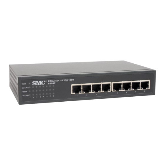
Internet access to multiple users. The following figures show the components of this switch: Front and Rear Panels SMC8505T EZSwitch 10/100/1000 EZSwitch 10/100/1000 8505T 8505T SMC8508T EZSwitch 10/100/1000 EZSwitch 10/100/1000 8508T 8508T... -
Page 15: Installing The Switch
• Appropriate DC power adapter • Rack-mount bracket kit • This User Guide • SMC Warranty Registration Card Mounting the Switch This switch can be placed directly on your desktop, or mounted in a rack. Before you start installing the switch, make sure you can provide the right operating environment, including power requirements, sufficient physical space, and proximity to other network devices that are to be connected. -
Page 16: Stacking Switches
NSTALLING THE WITCH • If you intend to mount the switch in a rack, make sure you have all the necessary mounting screws, brackets, bolts and nuts, and the right tools. • Check if network cables and connectors needed for installation are available. -
Page 17: Connecting The Switch System
ONNECTING THE WITCH YSTEM 4. Position the switch in the rack by lining up the holes in the brackets with the appropriate holes on the rack, and then use the rack-mount screws to mount the switch in the rack. Connecting the Switch System The EZ Switch 10/100/1000 provides 5/8 RJ-45 ports on this device. - Page 18 NSTALLING THE WITCH Ethernet connections. When inserting an RJ-45 plug, be sure the tab on the plug clicks into position to ensure that it is properly seated. Using the switch in a stand-alone configuration, you can network up to 8 end nodes. Caution: Do not plug a phone jack connector into any RJ-45 port.
-
Page 19: Powering On The Switch
OWERING N THE WITCH Powering On the Switch 1. Plug the power cord into the power socket at the rear of the switch, and the other end into a power outlet. 2. Check the LED marked Power on the front panel to see if it is on. The unit will automatically select the setting that matches the connected input voltage. -
Page 20: Verifying Port Status
NSTALLING THE WITCH Verifying Port Status The front panel of the switch provides status LEDs for “at-a-glance” system monitoring. The following table details the functions of the various indicators: EZSwitch 10/100/1000 EZSwitch 10/100/1000 8508T 8508T Port and System Status LEDs Condition Status Power... -
Page 21: Applications
PPLICATIONS LED indicator will light up for the corresponding port. If the port LED indicator fails to light when you connect a device to the switch, check the following items: • Be sure all network cables and connectors are properly attached to the connected device and the switch. - Page 22 00 0 00 /1 00 /1 10 /1 10 /1 itc h itc h EZ Sw EZ Sw 85 08 85 08 SMC-EZ109DT Link Activi WLAN Notebook SMC2804WBR Wireless Broadband Router Workstations With SMC9452TX Gigabit Workstations PCI Cards Notebook with...
-
Page 23: Product Specifications
RODUCT PECIFICATIONS Physical Characteristics Standards Conformance IEEE 802.3 IEEE 802.3u IEEE 802.3x IEEE 802.3ab Communication Rate 10/100/1000 Mbps Communication Mode Full or half duplex at 10/100 Mbps full duplex at 1000 Mbps Media Supported 10BASE-T - 100-ohm Category 3, 4, 5 twisted-pair 100BASE-TX - 100-ohm Category 5 twisted pair 1000BASE-T - 100-ohm Category 5 or 5e twisted-pair Number of Ports... -
Page 24: Emc/Safety Compliances
RODUCT PECIFICATIONS Weight SMC8505T: 0.59 kg (1.309 lbs) SMC8508T: 0.62 kg (1.378 lbs) MAC Address Table 8 K entries Memory Buffer 768 Kbits per unit Power Consumption SMC8505T: 12 Watts SMC8508T: 15 Watts Power Requirement DC input SMC8505T: 12 V, 1 A SMC8508T: 12 V, 1.25 A Temperature Operating: 0 ~ 40 ºC / 32 ~ 98 ºF... -
Page 25: Troubleshooting
IAGNOSING WITCH NDICATORS ROUBLESHOOTING Diagnosing Switch Indicators Symptom Power LED does not light after power on. Probable Causes Power outlet or power cord may be defective. Possible Solutions • Check for loose connections. • Check the power outlet by using it for another device. •... -
Page 26: Power And Cooling Problems
ROUBLESHOOTING Power and Cooling Problems If the power indicator does not turn on when the power cord is plugged in, you may have a problem with the power outlet, power cord, or internal power supply as explained in the previous section. However, if the unit powers off after running for a while, check for loose power connections, power losses or surges at the power outlet, and verify that the fans on the right side of the unit are unobstructed and running prior to shutdown. -
Page 27: Cables
EMC/S AFETY OMPLIANCES ABLES Cable Specifications Cable Types and Specifications Cable Type Max. Length Connector 10BASE-T Cat. 3, 4, 5 100-ohm UTP 100 m (328 ft) RJ-45 100BASE-TX Cat. 5 100-ohm UTP 100 m (328 ft) RJ-45 1000BASE-T Cat. 5 or Cat. 5e 100-ohm 100 m (328 ft) RJ-45 10BASE-T/100BASE-TX... -
Page 28: 1000Base-T Pin Assignments
ABLES The table below shows the 10BASE-T/100BASE-TX MDI-X and MDI port pinouts. MDI-X Signal Name MDI Signal Name Receive Data plus (RD+) Transmit Data plus (TD+) Receive Data minus (RD-) Transmit Data minus (TD-) Transmit Data plus (TD+) Receive Data plus (RD+) Transmit Data minus (TD-) Receive Data minus (RD-) 4,5,7,8... -
Page 29: 1000Base-T Cable Requirements
ABLE ESTING FOR XISTING ATEGORY ABLE 1000BASE-T Cable Requirements All Category 5 UTP cables that are used for 100BASE-TX connections should also work for 1000BASE-T, providing that all four wire pairs are connected. However, it is recommended that for all critical connections, or any new cable installations, Category 5e (enhanced Category 5) cable should be used. - Page 30 ABLES...
- Page 32 97 14 299 4466 Fax 97 14 299 4664 Thailand: 66 2 651 8733 Fax 66 2 651 8737 If you are looking for further contact information, please visit www.smc.com, www.smc-europe.com, or www.smc-asia.com. Model Number: SMC8505T, SMC8508T Pub. Number: 150000005200H E072003-R01...