Table of Contents
Advertisement
Available languages
Available languages
Advertisement
Table of Contents

Related Manuals for MSI MS-7235


Summary of Contents for MSI MS-7235
- Page 1 P965 Neo Series MS-7235 (V1.X) Mainboard G52-72351X5...
-
Page 2: Copyright Notice
If a problem arises with your system and no solution can be obtained from the user’s manual, please contact your place of purchase or local distributor. Alternatively, please try the following help resources for further guidance. Visit the MSI website for FAQ, technical guide, BIOS updates, driver updates, and other information: faq/esc_faq_list.php Contact our technical staff at: http://support.msi.com.tw... -
Page 3: Safety Instructions
Safety Instructions Always read the safety instructions carefully. Keep this User’s Manual for future reference. Keep this equipment away from humidity. Lay this equipment on a reliable flat surface before setting it up. The openings on the enclosure are for air convection hence protects the equip- ment from overheating. -
Page 4: Fcc-B Radio Frequency Interference Statement
This device complies with Part 15 of the FCC Rules. Operation is subject to the following two conditions: (1) this device may not cause harmful interference, and (2) this device must accept any interference received, including interference that may cause undesired operation. Micro-Star International MS-7235... -
Page 5: Weee (Waste Electrical And Electronic Equipment) Statement
WEEE (Waste Electrical and Electronic Equipment) Statement... -
Page 8: Table Of Contents
CONTENTS Copyright Notice ... ii Trademarks ... ii Revision History ... ii Technical Support ... ii Safety Instructions ... iii FCC-B Radio Frequency Interference Statement ... iv W EEE (Waste Electrical and Electronic Equipment) Statement ... v English ... En-1 Central Processing Unit: CPU ... -
Page 9: Installation Guide
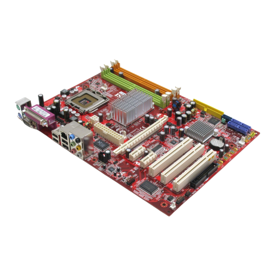
Specifications Processor Support ® - Intel Pentium 4, Pentium D, Core 2 series processors in LGA775 package For the latest information about CPU, please visit http://www.msi.com.tw/program/products/mainboard/mbd/ pro_mbd_cpu_support.php Supported FSB - 1066/ 800/ 533 MHz Chipset ® - North Bridge: Intel P965 chipset ®... - Page 10 M S-7235 M ainboard Layout of P965 Neo Series (MS-7235 v1.X) ATX Mainboard En-2...
-
Page 11: How To Use This Installation Guide
“How to use this Installation Guide?” This installation guide is designed for you to easily install the mainboard. Follow the steps below to use this guide: - Read the specifications of the mainboard first on page En-1. - Find out the component with the component number at your desire from the layout of the mainboard on page En-2. - Find out the component description and installing instructions with the “Components Index Table”... -
Page 12: Central Processing Unit: Cpu
® The mainboard supports Intel processor. The mainboard uses a CPU socket called Socket-775 for easy CPU installation. For the latest information about CPU, please visit http://www.msi.com.tw/program/products/mainboard/mbd/ pro_mbd_cpu_support.php. Important Overheating Overheating will seriously damage the CPU and system, always make sure the cooling fan can work properly to protect the CPU from overheating. -
Page 13: Memory
Memory Specification : 184-pin, 2.5v. Single channel definition : All DIMM slots are GREEN color. Dual channels definition : DIMM slot(s) on Channel A are marked in GREEN color. DIMM slot(s) on Channel B are marked in Purple color. 40x2=80 pin DDRII Specification : 240-pin, 1.8v. -
Page 14: Connectors, Jumper, Slots
M S-7235 M ainboard Connectors, Jumper, Slots Fan Power Connectors The fan power connectors support system cooling fan with +12V. The CPUFAN1 supports Smart FAN function. When connect the wire to the connectors, always take note that the red wire is the positive and should be connected to the +12V, the black wire is Ground and should be connected to GND. - Page 15 Front Panel Connectors These two front panel connectors are used for electrical connection to the front panel switches and LEDs. JFP1 is compliant ® with Intel Front Panel I/O Connectivity Design Guide. Power Power Switch JFP1 Reset Switch Front USB 2.0 Connector (Yellow) USB 2.0 technology increases data transfer rate up to a maximum throughput of 480Mbps, which is 40 times faster than USB 1.1, and is ideal for connecting high-speed USB interface peripherals such as USB HDD, digital cameras, MP3 players, printers, modems and the like.
- Page 16 M S-7235 M ainboard Front Panel Audio Connector The front panel audio connector allows you to connect to the front panel audio and ® is compliant with Intel Front Panel I/O Connectivity Design Guide. AUD_GND AUD_MIC AUD_MIC_BIAS AUD_VCC AUD_FPout_R AUD_RET_R HP_ON AUD_FPout_ L AUD_RET_L...
- Page 17 D-Bracket™ 2 Connector The connector is for you to connect D-Bracket™ 2. D-Bracket™ 2 is a external USB Bracket that support both USB1.1 & 2.0 spec. It integrates four LEDs and allows users to identify system problem through 16 various combinations of LED signals.
- Page 18 M S-7235 M ainboard Clear CMOS Button The CMOS RAM onboard has a power supply from external battery to keep the data of system configuration. With the CMOS RAM, the system can automatically boot OS every time it is turned on. If you want to clear the system configuration, use the Clear CMOS Button to clear data.
- Page 19 PCI Express Slots (x16/ x4/ x1) The PCI Express slot, as a high-bandwidth, low pin count, serial, interconnect technology. PCI Express architecture provides a high performance I/O infrastructure for Desktop Platforms with transfer rates starting at 2.5 Giga transfers per second over a PCI Express x1 lane for Gigabit Ethernet, TV Tuners, 1394 controllers, and general purpose I/O.
-
Page 20: Back Panel
M S-7235 M ainboard Back Panel Mouse/Keyboard Connector ® The standard PS/2 mouse/keyboard mini DIN connector for attaching a PS/2 mouse/keyboard directly into this connector. The connector location and pin assignments are as follows: Parallel Port Connector A parallel port is a standard printer port that supports Enhanced Parallel Port (EPP) and Extended Capabilities Parallel Port (ECP) mode. - Page 21 LAN (RJ-45) Jack The standard RJ-45 jack for connection to single Local Area Network (LAN). You can connect a network cable to it. Activity Indicator Color LED State Left Orange On (steady state) On (brighter & pulsing) Green Right Orange USB Connectors The OHCI (Open Host Controller Interface) Universal Serial Bus root for attaching USB devices such as keyboard, mouse, or other USB-compatible devices.
-
Page 22: Bios Setup
M S-7235 M ainboard BIOS Setup This chapter provides basic information on the BIOS Setup program and allows you to configure the system for optimum use. You may need to run the Setup program when: * An error message appears on the screen during the system booting up, and requests you to run BIOS SETUP. * You want to change the default settings for customized features. - Page 23 Installation Guide The Main Menu ® ® Once you enter AMI or AWARD BIOS CMOS Setup Utility, the Main Menu will appear on the screen. The Main Menu allows you to select from ten setup functions and two exit choices. Use arrow keys to select among the items and press <Enter>...
-
Page 24: Software Information
Utility menu - The Utility menu shows the software applications that the mainboard supports. WebSite menu- The WebSite menu shows the necessary websites. Important Please visit the MSI website to get the latest drivers and BIOS for better system performance. En-16 ) to highlight the Load Optimized Defaults field and press... - Page 25 Spezifikationen Prozessoren Unterstützt ® - Intel Pentium 4, Pentium D, Core 2 Series Prozessoren im LGA775 Package Um die neuesten Informationen zu unterstützten Prozessoren zu erhalten, besuchen Sie bitte http://www.msi. com.tw/program/products/mainboard/mbd/pro_mbd_cpu_support.php Unterstützt FSB - 1066/ 800/ 533 MHz Chipsatz ®...
- Page 26 M S-7235 M ainboard Layout of P965 Neo Series (MS-7235 v1.X) ATX Mainboard De-2...
- Page 27 “Wie Sie diese Installationsanleitung verwenden.” Diese Installationsanleitung wurde so gestaltet, dass Sie Ihnen die einfache Installation Ihres Mainboards ermöglicht. Folgen Sie den Schritten unten zur Nutzung dieser Anleitung: - Lesen Sie zunächst die Spezifikationen dieses Mainboards auf der Seite De-1 durch. - Identifizieren Sie die fragliche Komponente anhand der Nummerierung im Mainboardlayout auf der Seite De-2.
-
Page 28: Hauptprozessor: Cpu
M S-7235 M ainboard Hauptprozessor: CPU ® Das Mainboard unterstützt Intel Prozessoren und verwendet hierfür einen CPU Sockel mit der Bezeichnung Sockel- 775, um das Einsetzen der CPU zu erleichtern. wichtig Überhitzung Überhitzung beschädigt die CPU und das System nachhaltig, stellen Sie stets eine korrekte Funktionsweise des CPU Kühlers sicher, um die CPU vor Überhitzung zu schützen. -
Page 29: Speicher
Speicher Spezifikation : 184-Pin, 2,5V. Bestimmung Einkanalbetrieb : Alle DIMM Slots sind GRÜN. Bestimmung Zweikanalbetrieb : Die DIMM Slot(s) des Kanals A sind in GRÜN gehalten. Die DIMM Slot(s) des Kanals B sind LILA. 40x2=80 Pin DDR 2 Spezifikation : 240-Pin, 1,8V. Bestimmung Einkanalbetrieb : Alle DIMM Slots sind GRÜN. -
Page 30: Anschlüsse, Steckbrücken Und Slots
M S-7235 M ainboard Anschlüsse, Steckbrücken und Slots Stromanschlüsse für Lüfter Die Anschlüsseunterstützen aktive Systemlüfter mit + 12V. Der Anschluss CPU FAN (Prozessorlüfter) unterstützt die Smart FAN Funktionalität. Wenn Sie den Anschluss herstellen, sollten Sie immer darauf achten, dass der rote Draht der positive Pol ist, und mit +12V verbunden werden sollte, der schwarze Draht ist der Erdkontakt und sollte mit GND verbunden werden. - Page 31 Frontpaneel Anschlüsse Diese zwei Anschlüsse für das Frontpaneel dienen zum Anschluss der Schalter und LEDs des Frontpaneels. JFP1 erfüllt die Anforderungen des “Intel Front Panel I/O Connectivity Design Guide“. System System- schalter JFP1 Fest- Reset- platten schalter USB 2.0 Vorderanschluss (Gelb) Die USB 2.0 T echnologie erhöht den Datendurchsatz auf maximal 480Mbps, 40 mal schneller als USB 1.1, und ist bestens geeignet, Hochgeschwindigkeits- USB- Peripheriegeräte anzuschließen, wie z.B.
- Page 32 M S-7235 M ainboard Audioanschluss des Frontpaneels Der Audio Vorderanschluss ermöglicht den Anschluss von Audioein- und - ausgängen eines Frontpaneels. Der Anschluss entspricht den Richtlinien des “ ® Intel Front Panel I/O Connectivity Design Guide”. AUD_GND AUD_MIC AUD_MIC_BIAS AUD_VCC AUD_FPout_R AUD_RET_R HP_ON AUD_FPout_ L...
- Page 33 D-Bracket™ 2 Anschluss Das Mainboard verfügt über einen Anschluss für das D-Bracket™ 2. Das D-Bracket™ 2 ist ein USB Slotblech, das die Spezifikationen von USB1.1 und 2.0 erfüllt. Es beinhaltet vier LEDs und ermöglicht es dem Anwender Probleme zu identifizieren, in dem es 16 unterschiedliche Kombinationen von LED Signalen ausgibt.
- Page 34 M S-7235 M ainboard Taster zur Löschung des CMOS Auf dem Mainboard gibt es einen sogenannten CMOS Speicher (RAM), der über eine Batterie gespeist wird und die Daten der Systemkonfiguration enthält. Er ermöglicht es dem Betriebssystem, mit jedem Einschalten automatisch hochzufahren.
- Page 35 PCI Express Sockel (x16/ x4/ x1) Die PCI Express Slots verwenden eine serielle Anschlusstechnologie, die sich durch eine hohe Bandbreite und eine niedrige Anzahl an Pins auszeichnet. Die PCI Express Architektur stellt eine Hochleistungs- Ein-/Ausgabe - Infrastruktur für Desktop Plattformen mit Datendurchsätzen zur Verfügung, die bei 2,5 Giga- Übertragungen pro Sekunde über eine PCI Express x1 Leitung für Gigabit- Lan, TV -Karten, 1394 Kontroller und allgemeine Ein- und Ausgabe anfängt.
-
Page 36: Hinteres Anschlusspaneel
M S-7235 M ainboard Hinteres Anschlusspaneel Maus-/Tastaturanschluss Das Mainboard verfügt über einen Standard PS/2 anzuschliessen. Sie können hier direkt eine PS/2 Parallele Schnittstelle Die Parallele Schnittstelle ist eine Standard Druckerschnittstelle, die ebenso als Enhanced Parallel Port (EPP) und als Extended Capabilities Parallel Port (ECP) betrieben werden kann. Serielle Schnittstelle Bei der Seriellen Schnittstelle handelt es sich um eine 16550A Hochgeschwindigkeitskommunikationsschnittstelle, die 16 Bytes FIFOs sendet/empfängt. - Page 37 LAN (RJ-45) Buchse Das Mainboard bietet eine Standard RJ-45 Buchse zum Anschluss an ein Lokales Netzwerk (Local Area Network - LAN). Hier kann ein Netzwerkkabel angeschlossen werden. . Aktivitätsanzeige Farbe LED Status Links Orange An (Dauerleuchten) An (heller & pulsierend) Grün Rechts Orange...
-
Page 38: Bios Setup
M S-7235 M ainboard BIOS Setup Dieses Kapitel enthält Informationen über das BIOS Setup und ermöglicht es Ihnen, Ihr System optimal auf Ihre Anforderungen einzustellen. Notwendigkeit zum Aufruf des BIOS besteht, wenn: * Während des Bootvorgangs des Systems eine Fehlermeldung erscheint und Sie zum Aufruf des BIOS SETUP aufgefordert werden. - Page 39 Installationsanleitung Das Hauptmenü ® ® Nachdem Sie das AMI oder AWARD BIOS CMOS Setup Utility, aufgerufen haben, erscheint das Hauptmenü. Es weist zehn Setup- Funktionen und zwei Arten das Menü zu verlassen auf. Verwenden Sie die Pfeiltasten, um im Menü zu navigieren und drücken Sie die Eingabetaste (<Enter>), um ein Untermenü...
-
Page 40: Software Information
Das Softwaremenü (Utility menu) - Das Softwaremenü füht die Anwendungsprogramme auf, die das Mainboard unterstützt. WebSite Menü- Das Website Menü zeigt die notwendigen Webseiten an. wichtig Um bessere Systemleistung zu erzielen, besuchen Sie bitte die MSI Webseite, um die letzen Treiber und das aktuellste BIOS herunterzuladen. De-16 ), um den Menüpunkt Load... - Page 41 - DDRII 800 SDRAM module de mémoire de 1GB n’est pas supporté - 4 DIMMs DDRII(240pin / 1.8V) Pour plus d’informations pour télécharger le support des modules de mémoire, veuillez visiter http://www.msi com.tw/program/products/mainboard/mbd/pro_mbd_trp_list.php - Supporte PCI LAN 10/100/1000 Fast Ethernet par Realtek 8110SC Audio ®...
- Page 42 M S-7235 M ainboard Carte Mère P965 Neo Séries (MS-7235 v1.X) ATX Fr-2...
- Page 43 “Comment utiliser ce manuel?” Ce manuel de l’utilisateur fournit des instructions pour installer la carte Mère . Veuillez suivre les instructions - Voyez la spécificités de la Carte Mère à la page Fr-1. - Découvrez le tableau avec le nombre composant de la disposition de la carte mère à la page Fr-2. - Découvrez la description composante et instruction d’installation avec le T ableau d’index Composant - Réglez le BIOS et installez le pilote/ utilitaire selon vos besoins Tableau d’Index Composant...
-
Page 44: Unité Central De Traitement: Cpu
M S-7235 M ainboard Unité Central De Traitement: CPU La carte mère supporte les processeurs Intel chaque CPU. Pour une mise à jour sur les informations relatives au CPU, veuillez visiter http://www.msi.com.tw/program/products/ mainboard/mbd/pro_mbd_cpu_support.php. importante Surchauffe Une surchauffe peut sérieusement endommager le CPU et le système, assurez vous toujours que le système de reffroidissement fonctionne correctement pour protéger le CPU d’une s urchauffe. -
Page 45: Mémoire
Mémoire Spécification : 184-pin, 2.5v. Définition de canal unique : Tous les slots DIMM sont Verts. Définition de canaux double : Slot(s) DIMM sur le canal A est en Vert. Slot(s) DIMM sur le canal B est en violet . 40x2=80 pin DDR 2 Spécification : 240-pin, 1.8v. - Page 46 M S-7235 M ainboard Connecteurs, Jumper, Slots Connecteurs Fan Power Les connecteurs au ventilateur du système supportent la puissance du ventilateur avec +12V. Le VENTILATEUR de CPU supporte la fonction futée de VENTILATEUR(Smart FAN). Quand vous reliez le fil aux connecteurs, notez que le fil rouge est positif et doit être relié...
- Page 47 Connecteur Panneau Avant La carte mère possède deux connecteurs pour la connexion électrique du panneau avant (led, switch). JFP1 est compatible ® avec l’Intel Front Panel I/O Connectivity Design Guide. Power Power Switch JFP1 Rese et Switch Connecteur Front USB 2.0 (jaune) La technologie USB 2.0 augmente le taux de transfert jusqu’ą...
- Page 48 M S-7235 M ainboard Connecteur facade audio Le connecteur facade audio vous permet de connecter la facade audio qui est ® compatible avec l’Intel Front Panel I/O Connectivity Design Guide. AUD_GND AUD_MIC AUD_MIC_BIAS AUD_VCC AUD_FPout_R AUD_RET_R HP_ON AUD_FPout_ L AUD_RET_L 9 10 importante Si vous ne voulez pas vous relier à...
- Page 49 Connecteur D-Bracket™ 2 Le connecteur est utilisé pour connecter le D-Bracket™ 2. Le D-Bracket™ 2 est un bracket USB externe qui supporte les spécifications USB1.1 & 2.0. Le D-Bracket est pourvu de 4 LED et permet d’identifier les problèmes et ce à l’aide de 16 combinaisons de couleurs pour de plus amples renseignements sur ces 16 signaux.
- Page 50 M S-7235 M ainboard Clear CMOS Bouton La mémoire du Bios est alimentée à partir de la pile afin de conserver les données de la configuration du système. Avec la mémoire du Bios, le système peut automatiquement démarrer sur l’OS à chaque fois lorsqu’il est allumé. Si vous voulez effacer la configuration du Bios, utilisez le bouton Clear CMOS.
- Page 51 Slots PCI Express (x16/ x4/ x1) Le slot PCI Express, comme une largeur de bande et un pin basse, compte une publication sérielle, une technologie d’interconnexion. L’architecture PCI Express fournit un rendement élevé I/O infrastructure pour les plateformes de bureau avec un taux de transfert de 2.5 de Giga par seconde sur une voie PCI Express x1pour Gigabit Ethernet, TV Tuners, contrôleurs 1394, et IO général.
-
Page 52: Panneau Arrière
M S-7235 M ainboard Panneau Arrière Connecteur Souris/Clavier ® Le connecteur PS/2 souris/clavier mini DIN est conçu pour attacher un PS/2 ® directement un PS/2 souris/clavier dans ce connecteur. Les connecteurs et les pins sont ainsi: Connecteur port Parallèle Un port parallèle est un port d’imprimante standard qui supporte le port parallèle amélioré (EPP, Enhanced Parallel Port) et le mode d’ECP(Extended Capabilities Parallel Port) Connecteur Port Sériel Le port série est un port de communication 16550A à... - Page 53 LAN (RJ-45) Jack Le standard RJ-45 jack est utile pour le raccordement au Réseau de Région Local (LAN). Vous pouvez relier un câble de réseau à celui-ci. Indicateur d’Activité Couleur LED Statu Éteint Gauche Orange Allumé(steady state) Allumé(brighter & pulsing) Éteint Vert Droite...
-
Page 54: Installation Du Bios
M S-7235 M ainboard Installation du BIOS Ce chapitre vous informe sur le programme d’installation du BIOS et vous permet de configurer le système pour un usage optimum. Vous pouvez installer le programme lorsque: * Un message d’erreur apparaît sur l’écran pendant que le système initialise et vous demande de mettre en marche l’INSTALLATION de BIOS. - Page 55 Installation Matériel Menu Principal ® ® BIOS CMOS Setup Utility, le menu apparaît à l’écran. Le Menu permet Une fois entré dans le AMI ou AWARD de sélectionner dix fonctions et deux choix de sortie de l’utilitaire. Utilisez les flèches pour vous diriger et utilisez la touche ENTREE pour sélectionner un élément ou entrer dans le sous-menu..
-
Page 56: Information De Logiciel
Menu de services – Il montre les applications logicielles supportées par la carte mčre. Le menu du site Web – Il montre les sites Web nécessaires. importante Veuillez visiter le site Web de MSI pour obtenir les derniers pilotes et BIOS pour améliorer l’ exécution du système de votre ordinateur Fr-16 ) pour accentuer le champ de Load Optimized ) servent à...