Table of Contents
Advertisement
Advertisement
Table of Contents

Related Manuals for MSI 845GEM Series


Summary of Contents for MSI 845GEM Series
- Page 1 845GEM/845GVM Series MS-6714 (v5.X) M-ATX Mainboard G52-M6714X9...
-
Page 2: Fcc-B Radio Frequency Interference Statement
Manual Rev: 5.1 Release Date: May 2004 FCC-B Radio Frequency Interference Statement This equipment has been tested and found to comply with the limits for a class B digital device, pursuant to part 15 of the FCC rules. These limits are designed to provide reasonable protection against harmful interference when the equipment is operated in a commercial environment. -
Page 3: Copyright Notice
Copyright Notice The material in this document is the intellectual property of MICRO-STAR INTERNATIONAL. We take every care in the preparation of this document, but no guarantee is given as to the correctness of its contents. Our products are under continual improvement and we reserve the right to make changes without notice. -
Page 4: Technical Support
Alternatively, please try the following help resources for further guidance. Visit the MSI homepage & FAQ site for technical guide, BIOS updates, driver updates, and other information: http://www.msi.com.tw & http://www.msi. -
Page 5: Table Of Contents
CONTENTS FCC-B Radio Frequency Interference Statement ............ii Copyright Notice ......................iii Revision History ......................iii Technical Support ......................iv Safety Instructions ...................... iv Chapter 1. Getting Started ................... 1-1 Mainboard Specifications .................. 1-2 Mainboard Layout ....................1-4 Chapter 2. Hardware Setup ................. 2-1 Quick Components Guide .................. - Page 6 Front Panel Connectors: JFP1 & JFP2 ............. 2-15 Front Panel Audio Connector: JAUDIO1 ..........2-16 Front USB Connector: JUSB1 ..............2-16 SPDIF-Out Connector: JSPDIF1 (Optional) ..........2-17 Chassis Intrusion Switch Connector: JCASE1 ........2-17 Jumpers ......................2-18 Clear CMOS Jumper: JBAT1 ..............2-18 Slots ........................
-
Page 7: Chapter 1. Getting Started
Thank you for purchasing 845GEM/845GVM (MS-6714 v5. ® X) Micro ATX mainboard. The 845GEM/845GVM is based on Intel 845GE/GV & ICH4 chipsets and provides 6 USB 2.0 ports for high- speed data transmission and one optional SPDIF pinheader for dig- ital audio transmission. -
Page 8: Mainboard Specifications
! Supports Intel ® P4 Northwood / Prescott (Socket 478) processor. ! Supports FSB 800MHz (overclocking spec), 533MHz and 400MHz. ! Supports 3.06GHz (and up) speed P4 processor. (For the latest information about CPU, please visit http://www.msi.com.tw/program/ products/mainboard/mbd/pro_mbd_cpu_support.php) Chipset ! Intel ®... - Page 9 Getting Started - 1 LAN RJ45 connector Audio ! AC97 link controller integrated in Intel ICH4 southbridge. ! Realtek ALC 655 codec is compliant with AC97 2.1 Spec and meets PC2001 audio performance requirement. LAN (Optional) ! PCI local bus single-chip Fast Ethernet Controller, RealTek RTL8101L. - With external 10/100 Base-T Lan transformer.
-
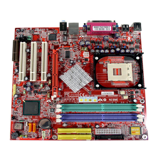
Page 10: Mainboard Layout
MS-6714 Micro-ATX Mainboard Mainboard Layout CPUFAN1 Top : mouse Bottom : keyboard USB ports Top : Parallel Port Bottom : COM1 VGA port JPW1 Top: LAN Jack Bottom : USB JCOM2 ports Intel (Optional) 845GE/GV Line-Out JCASE 1 Line-In Winbond AGP Slot (for 845GE only) W83627HF-AW BATT... -
Page 11: Chapter 2. Hardware Setup
Hardware Setup Chapter 2. Hardware Setup Hardware Setup This chapter tells you how to install the CPU, memory modules, and expansion cards, as well as how to setup the jumpers on the mainboard. Also, it provides the instructions on connecting the pe- ripheral devices, such as the mouse, keyboard, etc. -
Page 12: Quick Components Guide
MS-6714 Micro-ATX Mainboard Quick Components Guide CPUFAN1, p.2-13 CPU, p.2-3 JPW1, p.2-8 DDR DIMMs, p.2-6 CONN1, p.2-8 FDD1, p.2-13 Back Panel I/O, p.2-9 IDE1, IDE2, p.2-14 JCOM2, p.2-10 (optional) JCASE1, p.2-17 AGP Slot, p.2-19 BATT (for 845GE only) CD_IN1, p.2-14 PCI Slots, p.2-19 JBAT1, p.2-18 JSPDIF1, p.2-17... -
Page 13: Central Processing Unit: Cpu
If you do not find the heat sink and cooling fan, contact your dealer to purchase and install them before turning on the computer. For the latest information about CPU, please visit http://www.msi.com.tw/ program/products/mainboard/mbd/pro_mbd_cpu_support.php CPU Core Speed Derivation Procedure... -
Page 14: Cpu Installation Procedures For Socket 478
MS-6714 Micro-ATX Mainboard CPU Installation Procedures for Socket 478 Please turn off the power and unplug the power cord before installing the CPU. Open Lever Sliding 90 degree Plate Pull the lever sideways away from the socket. Make sure to raise the lever up to a 90-de- gree angle. -
Page 15: Installing The Cpu Fan
5. Connect the fan power cable from the mounted fan to the 3-pin fan power connector on the board. MSI Reminds You... fan power cable If your Intel Pentium 4 proces- sor supports 3.0GHz (and up), please be sure to use a... -
Page 16: Memory
DDR333 or DDR266 modules on the DDR DIMM slots (DDR 1~2). However, if you are using a CPU with FSB800 and you wish to overclock, you must install DDR400 modules. For the updated supporting memory modules, please visit http://www.msi. com.tw/program/products/mainboard/mbd/pro_mbd_trp_list.php. DDR DIMM Slots (DDR 1&2, from left to right) -
Page 17: Ddr Module Combination
2. Insert the DIMM memory module vertically into the DIMM slot. Then push it in until the golden finger on the memory module is deeply inserted in the socket. MSI Reminds You... You can barely see the golden finger if the module is properly inserted in the socket. -
Page 18: Power Supply
This 12V power connector is used to provide power to the CPU. CONN1 Pin Definition SIGNAL SIGNAL 3.3V 3.3V 3.3V -12V PS_ON PW_OK CONN1 5V_SB JPW1 Pin Definition SIGNAL JPW1 MSI Reminds You... Power supply of 300 (and up) watts is highly recommended for system stability. -
Page 19: Back Panel
Hardware Setup Back Panel The back panel provides the following connectors: Parallel Port Mouse Line In USB Ports Line Out Mic In Keyboard COM port VGA port USB Ports Mouse Connector The mainboard provides a standard PS/2 ® mouse mini DIN connector for at- ®... -
Page 20: Serial Port Connectors: Com1 & Jcom2 (Optional)
MS-6714 Micro-ATX Mainboard Serial Port Connectors: COM1 & JCOM2 (Optional) The mainboard offers one 9-pin male DIN connector as serial port COM1 and one optional serial port JCOM2. All ports are 16550A high speed communication ports that send/receive 16 bytes FIFOs. You can attach a serial mouse or other serial device directly to them. -
Page 21: Vga Connector
Hardware Setup VGA Connector The mainboard provides a DB 15-pin female connector to connect a VGA monitor. Signal Description Pin Signal Description GREEN BLUE VGA Connector Horizontal Sync Vertical Sync (DB 15-pin) RJ-45 LAN Jack The mainboard provides one standard RJ-45 jack for connection to Local Area Network (LAN). -
Page 22: Parallel Port Connector: Lpt1
MS-6714 Micro-ATX Mainboard Parallel Port Connector: LPT1 The mainboard provides a 25-pin female centronic connector as LPT. A parallel port is a standard printer port that supports Enhanced Parallel Port (EPP) and Extended Capabilities Parallel Port (ECP) mode. Pin Definition SIGNAL DESCRIPTION STROBE... -
Page 23: Connectors
+12V +12V SENSOR CPUFAN1 SYSFAN1 MSI Reminds You... 1. Always consult the vendors for proper CPU cooling fan. ® 2. Please refer to the recommended CPU fans at Intel official website. 3. If you want to overclock the CPU, it is strongly recommended to use a multi-direction fan for better heatsink. -
Page 24: Hard Disk Connectors: Ide1 & Ide2
IDE2 (Secondary IDE Connector) IDE2 can also connect a Master and a Slave drive. MSI Reminds You... If you install two hard disks on cable, you must configure the second drive to Slave mode by setting its jumper. Refer to the hard disk documentation supplied by hard disk vendors for jumper setting instructions. -
Page 25: Front Panel Connectors: Jfp1 & Jfp2
Hardware Setup Front Panel Connectors: JFP1 & JFP2 The mainboard provides two front panel connectors for electrical connection ® to the front panel switches and LEDs. JFP1 is compliant with Intel Front Panel I/O Connectivity Design Guide. Power Power Switch Speaker Power JFP1... -
Page 26: Front Panel Audio Connector: Jaudio1
Left channel audio signal to front panel AUD_RET_L Left channel audio signal return from front panel MSI Reminds You... If you don’t want to connect to the front audio header, pins 5 & 6, 9 & 10 have to be jumpered in order to have signal output directed to the rear audio ports. -
Page 27: Spdif-Out Connector: Jspdif1 (Optional)
Hardware Setup SPDIF-Out Connector: JSPDIF1 (Optional) This connector is used to connect SPDIF (Sony & Philips Digital Interconnect Format) interface for digital audio transmission. JSPDIF1 Pin Definition SIGNAL DESCRIPTION JSPDIF1 VCC5V SPDIF S/PDIF Output SPDIF Ground The JSPDIF1 supports SPDIF output only and can be connected to an external SPDIF Bracket for digital audio transmission. -
Page 28: Jumpers
JBAT1 Clear Data Keep Data MSI Reminds You... You can clear CMOS by shorting 1-2 pin while the system is off. Then return to 2-3 pin position. Avoid clearing the CMOS while the system is on; it will damage the mainboard. -
Page 29: Slots
Hardware Setup Slots The motherboard provides one optional AGP slot, three 32-bit PCI bus slots and one CNR slot. AGP (Accelerated Graphics Port) Slot (for 845GE only) The AGP slot allows you to insert the AGP graphics card. AGP is an interface specification designed for the throughput demands of 3D graphics. -
Page 30: Chapter 3. Bios Setup
SETUP. ! You want to change the default settings for customized features. MSI Reminds You... 1. The items under each BIOS category described in this chapter are under continuous update for better system performance. -
Page 31: Entering Setup
MS-6714 Micro-ATX Mainboard Entering Setup Power on the computer and the system will start POST (Power On Self Test) process. When the message below appears on the screen, press <DEL> key to enter Setup. P r e s s D E L e n t e r S E T U P If the message disappears before you respond and you still wish to enter... -
Page 32: The Main Menu
BIOS Setup The Main Menu Once you enter Award ® BIOS CMOS Setup Utility, the Main Menu (figure below) will appear on the screen. The Main Menu allows you to select from twelve setup functions and two exit choices. Use arrow keys to select among the items and press <Enter>... - Page 33 MS-6714 Micro-ATX Mainboard Load BIOS Setup Defaults Use this menu to load factory default settings into the BIOS for stable system perfor- mance operations. Set Supervisor Password Use this menu to set Supervisor Password. Set User Password Use this menu to set User Password. Save &...
-
Page 34: Standard Cmos Features
BIOS Setup Standard CMOS Features The items in Standard CMOS Features Menu includes some basic setup items. Use the arrow keys to highlight the item and then use the <PgUp> or <PgDn> keys to select the value you want in each item. Date The date format is <day>... - Page 35 MS-6714 Micro-ATX Mainboard Drive A/B This item allows you to set the type of floppy drives installed. Available options: [None], [360K, 5.25 in.], [1.2M, 5.25 in.], [720K, 3.5 in.], [1.44M, 3.5 in.], [2.88M, 3.5 in]. Video The setting controls the type of video adapter used for the primary monitor of the system.
-
Page 36: Advanced Bios Features
[Enabled] will increase the system performance. Settings: [Enabled], [Disabled]. Please disable this item if your operating system doesn’t support HT Function, or unreliability and instability may occur. MSI Reminds You... Enabling the functionality of Hyper-Threading Technology for your com- puter system requires ALL of the following platform Components: ®... - Page 37 The items allow you to set the sequence of boot devices where BIOS attempts to load the disk operating system. MSI Reminds You... Available settings for “1st/2nd/3rd Boot Device” vary depending on the bootable devices you have installed. For example, if you did not install a floppy drive, the setting “Floppy”...
- Page 38 BIOS Setup Option Description [Setup] The password prompt appears only when end users try to run Setup. [System] A password prompt appears every time when the computer is powered on or when end users try to run Setup. APIC Mode This field is used to enable or disable the APIC (Advanced Programmable Interrupt Controller).
-
Page 39: Advanced Chipset Features
MS-6714 Micro-ATX Mainboard Advanced Chipset Features MSI Reminds You... Change these settings only if you are familiar with the chipset. Configure DRAM Timing Selects whether DRAM timing is controlled by the SPD (Serial Presence Detect) EEPROM on the DRAM module. Setting to [By SPD] enables DRAM timings to be determined by BIOS based on the configurations on the SPD. - Page 40 BIOS Setup DRAM Frequency This setting allows you to set the bus frequency for installed DRAM. Settings: [Auto], [DDR266], [DDR333]. Delayed Transaction The chipset has an embedded 32-bit posted write buffer to support delayed transac- tions cycles so that transactions to and from the ISA bus are buffered and PCI bus can perform other transactions while the ISA transaction is underway.
-
Page 41: Integrated Peripherals
MS-6714 Micro-ATX Mainboard Integrated Peripherals OnChip IDE Device Press <Enter> and the following sub-menu appears: IDE HDD Block Mode Block mode is also called block transfer, multiple commands, or multiple sector read/write. If your IDE hard drive supports block mode (most new drives do), select [Enabled] for automatic detection of the optimal number of block read/ writes per sector the drive can support. - Page 42 BIOS Setup supports it and the operating environment includes a DMA driver (Windows ME, XP or a third-party IDE bus master driver). If your hard drive and your system software both support Ultra DMA/33, Ultra DMA/66, Ultra DMA/100 and Ultra DMA/133, select Auto to enable BIOS support.
- Page 43 MS-6714 Micro-ATX Mainboard POWER ON Function This controls how the PS/2 mouse or keyboard can power on the system. Settings: [Password], [Hot KEY], [Mouse Left], [Mouse Right], [Any KEY], [BUTTON ONLY], [Keyboard 98]. KB Power ON Password If POWER ON Function is set to [Password], then you can set a password in the field for the PS/2 keyboard to power on the system.
- Page 44 BIOS Setup IR Transmission Delay This setting determines whether the IR transmission rate will be delayed while converting to receiving mode. Setting options: [Disabled], [Enabled]. IR Duplex Mode This setting controls the operating mode of IR transmission/reception. Set- ting options: [Full], [Half]. Under [Full] mode, synchronous, bi-directional transmission/reception is allowed.
-
Page 45: Power Management Setup
MS-6714 Micro-ATX Mainboard Power Management Setup IPCA Function This item is to activate the IPCA (Advanced Configuration and Power Management Interface) Function. If your operating system is ACPI-aware, such as Windows 98SE/ 2000/ME, select [Enabled]. Settings: [Enabled] and [Disabled]. ACPI Standby State This item specifies the power saving modes for ACPI function. - Page 46 Settings: [Enabled], [Disabled]. MSI Reminds You... When the computer loses its power, the above functions - Wake Up On PME & USB Wakeup From S3 (S4) will be unavailable.
- Page 47 * Time (hh:mm:ss) Alarm The field specifies the time for Resume by Alarm. Format is <hour><minute> <second>. MSI Reminds You... S3-related functions described in this section are available only when your BIOS supports S3 sleep mode. ** Reload Global Timer Events ** Primary/Secondary Master/Slave IDE, FDC/COM/LPT Ports The global timer is the hardware timer that counts down to the power saving modes.
-
Page 48: Pnp/Pci Configuration
BIOS Setup PNP/PCI Configurations This section describes configuring the PCI bus system and PnP (Plug & Play) feature. PCI, or Peripheral Component Interconnect, is a system which allows I/O devices to operate at speeds nearing the speed the CPU itself uses when communi- cating with its special components. - Page 49 MS-6714 Micro-ATX Mainboard IRQ Resources list IRQ 3/4/5/7/9/10/11/12/14/15 for users to set each IRQ a type depending on the type of device using the IRQ. Settings are: [PCI Device] For Plug & Play compatible devices designed for PCI bus architecture. [Reserved] The IRQ will be reserved for further request.
-
Page 50: Pc Health Status
BIOS Setup PC Health Status This section shows the status of your CPU, fan, overall system status, etc. Monitor function is available only if there is hardware monitoring mechanism onboard. Chassis Intrusion Detect The field enables or disables the feature of recording the chassis intrusion status and issuing a warning message if the chassis is once opened. - Page 51 , then the CPU fan will speed up to [FF], which is the CPU full speed, to avoid overheating damage. MSI Reminds You... If you are using a CPU with FSB800, and you load High Performance Defaults, the CPU Fan Control is disabled.
-
Page 52: Frequency/Voltage Control
BIOS Setup Frequency/Voltage Control Use this menu to specify your settings for frequency/voltage control. CPU Ratio Selection This setting controls the multiplier that is used to determine the internal clock speed of the processor relative to the external or motherboard clock speed. It is available only when the processor supports this function. -
Page 53: Load High Performance/Bios Setup Defaults
Pressing <Enter> loads the default BIOS values that enable the best system performance but may lead to a stability issue. MSI Reminds You... If you have a DDR400 memory module (or more) installed on your system, and you are using a CPU with FSB 800MHz and you wish to overclock, you must load this High Performance Defaults. -
Page 54: Set Supervisor/User Password
Option is set to [System], the password is required both at boot and at entry to Setup. If set to [Setup], password prompt only occurs when you try to enter Setup. MSI Reminds You... About Supervisor Password & User Password: Supervisor password: Can enter and change the settings of the setup menu. -
Page 55: Appendix A: Using 2-, 4- & 6-Channel Audio Function
Using 2-, 4- & 6-Channel Audio Function Appendix A: Using 2-, 4- & 6-Channel Audio Function The mainboard is equipped with Realtek ALC655 chip, which provides sup- port for 6-channel audio output, including 2 Front, 2 Rear, 1 Center and 1 Subwoofer channel. -
Page 56: Installing The Audio Driver
2. Click Realtek AC97 Audio Drivers. Click here MSI Reminds You... The AC97 Audio Configuration s o f t w a r e u t i l i t y i s u n d e r continuous update to enhance audio applications. Hence, the program screens shown here in this appendix may be slightly different from the latest software utility and shall be held for reference only. - Page 57 Using 2-, 4- & 6-Channel Audio Function 3. Click Next to install the AC’ 9 7 Audio software. Click here 4. Click Finish to restart the system. Select this option Click here A - 3...
-
Page 58: Software Configuration
MS-6714 Micro-ATX Mainboard Software Configuration After installing the audio driver, you are able to use the 4-/6-channel audio feature now. Click the audio icon from the window tray at the lower-right corner of the screen to activate the AC97 Audio Configuration. Sound Effect Here you can select a sound effect you like from the Environment list. - Page 59 Using 2-, 4- & 6-Channel Audio Function Here it provides the Karaoke function which will automatically remove human voice (lyrics) and leave melody for you to sing the song. Note that this function applies only for 2-channel audio operation. Just check the Voice Cancellation box and then click OK to activate the Karaoke function.
-
Page 60: Equalizer
MS-6714 Micro-ATX Mainboard Equalizer Here you regulate each equalizer for current playing digital sound sources. You may choose the provided sound effects, and the equalizer will adjust automatically. If you like, you may also load an equalizer setting or make an new equalizer setting to save as an new one by using the buttons Load and Save. -
Page 61: Speaker Configuration
Using 2-, 4- & 6-Channel Audio Function Speaker Configuration In this tab, you can easily configure your multi-channel audio function and speakers. Select Synchronize the phonejack switch with the settings. Select a desired multi-channel operation from No. of Speakers. Headphone 2-Channel Mode for Stereo-Speaker Output 4-Channel Mode for 4-Speaker Output 6-Channel Mode for 5.1-Speaker Output... -
Page 62: Speaker Test
MS-6714 Micro-ATX Mainboard Speaker Test You can use this tab to test each connected speaker to ensure if 4- or 6- channel audio operation works properly. If any speaker fails to make sound, then check whether the cable is inserted firmly to the connector or replace the bad speakers with good ones. -
Page 63: Hrtf Demo
Using 2-, 4- & 6-Channel Audio Function MSI Reminds You... 1. 6 speakers appear on the “Speaker Test” tab only when you select “6-Channel Mode” in the “Number of Speakers” column in “Speaker Configuration” tab. If you select “4-Channel Mode”, only 4 speakers appear on the window. -
Page 64: General
MS-6714 Micro-ATX Mainboard General In this tab it provides some information about the AC97 Audio Configuration utility, including Audio Driver Version, DirectX Version, Audio Controller & AC97 Codec. You may also select the language of this utility by choosing from the Language list. A - 1 0... -
Page 65: Using 2-, 4- & 6-Channel Audio Function
Using 2-, 4- & 6-Channel Audio Function Using 2-, 4- & 6- Channel Audio Function Connecting the Speakers When you have set the Multi-Channel Audio Function mode properly in the software utility, connect your speakers to the correct phone jacks in accord- ance with the setting in software utility. - Page 66 MS-6714 Micro-ATX Mainboard ! 4-Channel Mode for 4-Speaker Output The audio jacks on the back panel always provide 2-channel analog audio output function, however these audio jacks can be transformed to 4- or 6- channel analog audio jacks by selecting the corresponding multi-channel operation from No.
- Page 67 Out function when 6-Channel Mode for 6-Speaker Output is selected. MSI Reminds You... If the audio signals coming from the Center and Subwoofer speaker are swapped when you play video or music on the computer, a con- verter may be required to exchange center and subwoofer audio signals.