Grizzly G0516 Owner's Manual
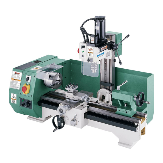
Combination lathe/mill
Hide thumbs
Also See for G0516:
- Instruction manual (72 pages) ,
- Parts list (16 pages) ,
- Owner's manual (64 pages)
Table of Contents
Advertisement
Quick Links
Download this manual
See also:
Instruction Manual
Advertisement
Table of Contents

Related Manuals for Grizzly G0516


Summary of Contents for Grizzly G0516
- Page 1 MODEL G0516 COMBINATION LATHE/MILL OWNER'S MANUAL COPYRIGHT © NOVEMBER, 2002 BY GRIZZLY INDUSTRIAL, INC. REVISED MARCH, 2008 (TR) WARNING: NO PORTION OF THIS MANUAL MAY BE REPRODUCED IN ANY SHAPE OR FORM WITHOUT THE WRITTEN APPROVAL OF GRIZZLY INDUSTRIAL, INC.
- Page 2 ���� ������ �������� �������� ������ ������������ �� ��� ������ ������ ���������� ����������� ��� ������� �� ���� ������������������ ������� �� ����� ���������� ��� ������ ��� ������������ ����� �� ���� ������ ��� ������ �� ������� �������� ������� ��������� ����������� ������������� �� ������ ���...
-
Page 3: Table Of Contents
Table of Contents SECTION 1: SAFETY ........2 SECTION 7: MILL/DRILL OPERATIONS ..30 Safety Instructions for Machinery ....2 Mill/Drill ............30 Additional Safety For Lathe/Mills ....4 Changing Chucks ........31 Installing Mill Table ........33 SECTION 2: CIRCUIT REQUIREMENTS ..5 110V Operation .......... -
Page 4: Section 1: Safety
����� ������� ���������� ������������ ���� ������������������������������������� ������������������� �� ����� ������� ��������� ���� �� ������ ���� � ����� �������� ����� �� ����� ��� ��������� �� ���������� ���� ��������� ����� �� �������� ������������������ ��������� ���� �������� ������ ������������������������������������ ������������������������������������������� ����������������������������������� G0516 Lathe/Mill... - Page 5 ��� �������� ��������� ���� ������ ��� ���� ������������ �������� ��� ������� ���� ����������������������������������������� ������������������������������������������� �������������������������������������������� ���� ����� ��� ����� ���� ���� �������� ��� ���� ������������������������������������� �������������������������������������������� ��� ���� ���� ������ ��� �� ����� ������������������ ��� ���� ��������� ������ ����� ���������� G0516 Lathe/Mill...
-
Page 6: Additional Safety For Lathe/Mills
DRILL CHUCK OR LATHE CHUCK. Like all power tools, there is danger asso- No list of safety guidelines can be complete. ciated with the Model G0516 Lathe/Mill. Every shop environment is different. Always Accidents are frequently caused by lack consider safety first, as it applies to your of familiarity or failure to pay attention. -
Page 7: Section 2: Circuit Requirements
SECTION 2: CIRCUIT REQUIREMENTS 110V Operation Power Connection Device The Model G0516 comes with a 5-15 plug, similar to Figure 1, to connect the machine to power. Serious personal injury could occur if you connect the machine to power before com- pleting the setup process. -
Page 8: Section 3: Introduction
Contact Info Foreword If you have any comments regarding this manual, We are proud to offer the Model G0516 Lathe/Mill. This machine is part of a growing Grizzly family of please write to us at the address below: fine metalworking machinery. When used accord- ing to the guidelines set forth in this manual, Grizzly Industrial, Inc. -
Page 9: Section 4: Identification
SECTION 4: IDENTIFICATION 10 11 Figure 2. The following is a list of controls and components on the Model G0516. Please take time to become familiar with each term and its location. These terms will be used throughout the manual and know- ing them is essential to understanding the instructions and terminology used in this manual. - Page 10 Figure 3. The picture above shows important accessories and tools that are included with the Model G0516. Please take some time to identify these items. Similar to the components and controls in Figure 2, these items are mentioned throughout the manual and knowing them is essential to understanding the instructions and terminology used in this manual.
-
Page 11: Section 5: Setup
Inside the crate you will find: This combination lathe/mill is shipped from the manufacturer in a carefully packed crate. If you • Model G0516 Lathe Unit ......... 1 discover the machine is damaged after you’ve • Mill/Drill Unit ............ 1 signed for delivery, and the truck and driver are •... -
Page 12: Clean Up
The machine must remain unplugged throughout entire assembly process. Failure Figure 4. Cleaner/degreaser available from to do this may result in Grizzly. serious personal injury. -10- G0516 Lathe/Mill... -
Page 13: Attach Mill/Drill To Lathe
Install the V-belt and cogged belt as shown in Figure 7. Figure 5. Threading nut onto bolt with mill/drill unit in place against mounting bracket. V-Belt Cogged Belt Figure 7. V-belt and cogged belt installed. G0516 Lathe/Mill -11-... -
Page 14: Mount Mill/Drill Eyeshield
Eyeshield Figure 8. Attaching eyeshield to the Figure 9. Eyeshield attached to lathe. mill/drill head. -12- G0516 Lathe/Mill... -
Page 15: Test Run Lathe
Note—If it is does not light up, unplug the machine and check the fuse, your power source, and the connec- tions on the machine before attempting to start the lathe. Call our Tech Support if you cannot easily resolve the issue. G0516 Lathe/Mill -13-... -
Page 16: Test Run Mill/Drill
15. Rotate the variable speed dial counterclock- wise as far as it will go. This should stop the drill chuck. 16. Press the mill/drill OFF button to turn the Figure 12. Mill/drill controls. mill/drill OFF. -14- G0516 Lathe/Mill... -
Page 17: Section 6: Lathe Operations
WE STRONGLY RECOMMEND that you read books, trade magazines, or get formal training to gain the skills needed to operate the lathe portion of your machine. G0516 Lathe/Mill -15-... -
Page 18: Removing Chuck
Place a piece of plywood over the bed-ways to protect your hands. or Faceplate ALWAYS place a piece The Model G0516 spindle nose mounting system of plywood over lathe uses a circular lock plate with slotted holes that bed-ways before remov- are oversized at one end (keyholes). -
Page 19: Installing Chuck
Faceplate Dead Center There are 2 dead centers included with the Model To install a chuck/faceplate: G0516. The smaller dead center is a MT#2 (Morse Taper) and fits in the tailstock barrel. Disconnect the lathe/mill from the power source! -
Page 20: Removing Tailstock Dead Center
The force of the center contacting a The tailstock on the Model G0516 clamps to the mounted workpiece will fully seat the taper bed with the nut shown in Figure 19. This nut when the handwheel is tightened. -
Page 21: Changing
Changing Tool Posts The Model G0516 comes with a turret tool post. Grizzly also offers quick change tool post as an optional accessory to the Model G0516. Both tool posts can be removed and replaced in the same manner. To change a tool post from the compound rest: Figure 21. -
Page 22: Adjusting
“0”, or your operation, remember to clear the back- lash before moving the cross slide forward to it will not be accurate. the “0” mark for the next cut. -20- G0516 Lathe/Mill... -
Page 23: Adjusting Carriage
Like most lathes, the longitudinal movement of When new, Model G0516 is geared for a car- the carriage (carriage feed) on the Model G0516 riage feed rate of .005" per revolution. -
Page 24: Understanding
Threading Charts—By arranging the gears as shown on the charts, you can set up the carriage Gear Charts feed to cut any of the thread pitches displayed. See Figure 27. The Model G0516 can be geared for a variety of �� � � �... - Page 25 Figure 31. Although the chart shows this as a blank spot, there should actually be a spacer in this position on the machine. This spacer is not listed on the chart, because the chart only reflects ACTIVE gear positions. G0516 Lathe/Mill -23-...
- Page 26 The boxes shaded in Figure 33 represent the actual gear combinations required to cut the thread pitches. 1" ⁄ In Mesh In Mesh Spacer Figure 33. The shaded boxes show specific gear Figure 35. Actual gear setup for .005" feed rate. setups. -24- G0516 Lathe/Mill...
-
Page 27: Changing Gears For Carriage Feed Rate
Disconnect the lathe/mill from the power source! Loosen the knurled knob shown in Figure 37, and open the drive cover. Drive Cover Knob Figure 39. Removing special lock washers from adjustable shaft. Figure 37. Knurled drive cover knob. G0516 Lathe/Mill -25-... - Page 28 Figure 41. Loosening gear bracket cap screw. the middle set of gears. 14. Pivot the gear bracket toward the drive gear so all the intended gears are in mesh. -26- G0516 Lathe/Mill...
-
Page 29: Reverse Threading
At this point, all gears should not be able to move out of position. The Model G0516 can be setup to turn left-hand- 16. Turn the the chuck by hand to make sure that ed threads by adding another fixed-shaft gear and all the gears turn smoothly. - Page 30 Spin the lathe chuck by hand to ensure that the gears do not bind. Replace the cover and test run the machine before proceeding with your specific opera- tion. Figure 46. Fixed-shaft gear mounted in position “C.” -28- G0516 Lathe/Mill...
-
Page 31: Changing Speeds
Move the pulley bracket away from the belt. Position the belt into the pulley sheaves that dictate the speed required for your opera- The Model G0516 features 6 speeds—150, 240, tion. 490, 750, 1200 & 2400 RPM. These speeds can... -
Page 32: Section 7: Mill/Drill Operations
The hub on the coarse downfeed handwheel ing to gain the skills needed for the operation must be engaged to use the micro downfeed of the mill/drill portion of your machine. knob. -30- G0516 Lathe/Mill... -
Page 33: Changing Chucks
Using a brass or wood hammer, tap the end of the draw nut as shown in Figure 55. The drill chuck should now become loose in the spindle. Figure 53. Removing mill/drill spindle cap. Figure 55. Tapping draw bolt loose with hammer. G0516 Lathe/Mill -31-... - Page 34 Firmly insert your collet chuck into the spindle taper. Insert the flat washer and thread the hex nut onto the end of the draw bolt. -32- G0516 Lathe/Mill...
-
Page 35: Installing Mill Table
6mm allen wrench with the table mounting cap screws. Figure 59 shows the milling table installed on the cross slide. The Model G0516 includes a milling table as an accessory. When the Model G0516 is shipped from the factory, the compound slide is mounted on the cross slide and must be removed before the milling table can be installed. -
Page 36: Section 8: Maintenance
Failure to Compound Slide Leadscrew Tailstock Barrel do this may result in seri- Tailstock Leadscrew ous personal injury. Right Leadscrew Support Figure 61. Ball fitting lubrication points. Figure 60. Lubrication ball fittings. -34- G0516 Lathe/Mill... -
Page 37: Checking V-Belt
8 hours of actual use. Carriage Rack—Apply a minimal amount directly on the rack every 8 hours of actual use. Mill/Drill Rack & Pinion—Apply a minimal amount directly on the rack every 8 hours of actual use. G0516 Lathe/Mill -35-... -
Page 38: Section 9: Service Adjustments
This section is provided for your convenience— Cross-slide Gib—The gib on the cross-slide it is not a substitute for the Grizzly Service is adjusted by tightening or loosening the 4 gib Department. If any adjustments arise that are not screws located on the right-hand side of the slide. - Page 39 See Figures 66 & 67. It is important the screws are tightened evenly. A slight drag should be detected while turning the hand crank at the end of the lathe. Figure 66. Front saddle gib screws. G0516 Lathe/Mill -37-...
-
Page 40: Aligning Tailstock
Aligning Tailstock The tailstock on the Model G0516 is aligned with the headstock at the factory. However, at times you may wish to misalign the tailstock for certain operations; then, realign it when you are finished. To align the tailstock: Center drill a 6'' long piece of round cold rolled stock on both ends. -
Page 41: Bearing Preload
Be careful not to move the tailstock out of position when tightening the adjustment screws. 10. Turn another .010'' off of the stock and check for taper. Repeat steps 7-9 as necessary until the desired amount of accuracy is achieved. G0516 Lathe/Mill -39-... -
Page 42: Machine Data Sheet
MACHINE DATA SHEET Customer Service #: (570) 546-9663 · To Order Call: (800) 523-4777 · Fax #: (800) 438-5901 MODEL G0516 COMBO LATHE W/ MILLING ATTACHMENT Product Dimensions: Weight................................397 lbs. Length/Width/Height..........................44 x 23 x 34 in. Foot Print (Length/Width)........................43 x 16-1/2 in. - Page 43 Quick Change Tool Post The information contained herein is deemed accurate as of 3/14/2008 and represents our most recent product specifications. Model G0516 PAGE 2 OF 2 Due to our ongoing improvement efforts, this information may not accurately describe items previously purchased.
- Page 44 -42- G0516 Lathe/Mill...
-
Page 45: Section 10: Parts
SECTION 10: PARTS G0516 Lathe/Mill -43-... - Page 46 P0516155 SMALL GEAR PROTECTOR P0516120 STEEL WASHER 30 X 16 X 4 P0516156 GREEN LAMP PS57M PHLP HD SCR M5-.8 X 14 P0516157 FUSE BOX P0516122 SWITCH LABEL P0516158 FUSE P0516123 SHAFT COVER P0516159 SELECTOR SWITCH P0516124 -44- G0516 Lathe/Mill...
- Page 47 ��� ��� ��� ��� ��� ��� ��� ��� ��� ��� ��� ��� ��� ��� ��� ��� ��� ��� ��� ��� ��� ��� ��� ��� ����� ��� ����� ��� ��� ��� ��� ����� ����� ��� ��� ����� ��� G0516 Lathe/Mill -45-...
- Page 48 COMBO WRENCH 12/14MM P0516232 3-JAW CHUCK D-125MM PWR810 WRENCH 8 X 10 232-1 P0516232-1 FACEPLATE 8-1/2" P0516264 WRENCH 5.5/7MM 232-2 P0516232-2 3-JAW CHUCK KEY P0516265 WRENCH 36MM 232-3 P0516232-3 OUTSIDE JAWS FOR 3-JAW CHUCK P0516266 TOOLPOST WRENCH -46- G0516 Lathe/Mill...
- Page 49 P0516326 BASE P0516312 HANDLE P0516327 ZERO POSITION SCALE P0516313 OIL CUP P0516328 SCALE RIVET P0516314 T-TAP FLAT KEY 12 X 12 X 7 P0516329 INDICATOR SCALE PS11M PHLP HD SCR M6-1 X 16 P0516330 TAILSTOCK CENTER MT2 G0516 Lathe/Mill -47-...
- Page 50 ��� P0516429 CARRIAGE HANDWHEEL P0516430 INDEX RING PS11M PHLP HD SCR M6-1 X 16 ��� P0516432 CYLINDER PIN 4 X 16 ��� ��� ��� ��� ��� ��� ��� ��� ��� ��� ��� ��� ��� ��� ��� ��� -48- G0516 Lathe/Mill...
- Page 51 MILLING TABLE PS39M PHLP HD SCR M8-1.25 X 10 PSB13M CAP SCREW M8-1.25 X 30 P0516520 GIB STRIP PRP58M ROLL PIN 6 X 45 P0516521 REAR-CLAMP PLATE P0516543 MILLING VISE PS56M PHLP HD SCR M4-.7 X 16 G0516 Lathe/Mill -49-...
- Page 52 P0516630 ROTATING SHAFT P0516614 INDEX RING P0516631 SHAFT SLEEVE P0516615 SMALL SHAFT SLEEVE P0516632 MOVING PLATE PRP73M ROLL PIN 4 X 30 PS07M PHLP HD SCR M4-.7 X 8 P0516617 SMALL GEAR SHAFT P0516634 CARRIAGE FEED NOTICE -50- G0516 Lathe/Mill...
- Page 53 G0516 Lathe/Mill -51-...
- Page 54 OPEN LOCK WASHER 25 X 7 X 5 PLABEL-27 MM CONVERSION CHART P6001 BALL BEARING 6001ZZ PN04M HEX NUT M4-.7 P0516822 GEAR Z:40 PS63M PHLP HD SCR M6-1 X 4 PR03M EXT RETAINING RING 12MM P0516851 HINGE P0516824 FRONT SHAFT SPACER P0516852 GEAR Z:65 -52- G0516 Lathe/Mill...
- Page 55 MAIN POWER SOCKET PR19M EXT RETAINING RING 28MM PLABEL-14 ELECTRICITY LABEL P0516923 PIVOT P0516949 QUICK CHANGE COLLET SET P0516924 PIVOT SPACER 949-1 P0516949-1 COLLET NUT PW04M FLAT WASHER 10MM 949-2 P0516949-2 COLLET SHAFT PN02M HEX NUT M10-1.5 G0516 Lathe/Mill -53-...
- Page 56 1153 1154 1151 1030 1132 1161 1065 1156 1155 1159 1067 1044 1163 1043 1041 1068 1068 1045 1040 1040-1 1162 1157 1042 1070 1071 1072 1200 1017 1039 1039-1 1201 1039-2 1202 1203 1204 1205 1206 -54- G0516 Lathe/Mill...
- Page 57 ���� ���� ���� ���� ���� ���� ���� ���� ���� ���� ���� ���� ���� ���� ���� ���� ���� ���� ���� ���� ���� ���� ���� ���� ���� ���� ���� ���� ���� ����� ���� ���� ���� ���� ���� ���� ���� G0516 Lathe/Mill -55-...
- Page 58 GUIDE FINGER 1097 PS17M PHLP HD SCR M4-.7 X 6 1062 PSB06M CAP SCREW M6-1 X 25 1098 P8689098 DUST COVER SUPPORT 1063 P05161063 SPINDLE BOX SEAT 1099 PS40M PHLP HD SCR M5-.8 X 16 1064 P05161064 WEDGE -56- G0516 Lathe/Mill...
- Page 59 PHLP HD SCR M6-1 X 8 1136 P05161136 LATHE FUSE F25A 250V 1204 P05161204 SUPPORT 1136A P05161136A MILL FUSE F5A L 250V 1205 P05161205 SUPPORT BOLT 25.4 X 16 X 140 1137 P05161137 STOP SWITCH 1206 P05161206 SUPPORT PLATE G0516 Lathe/Mill -57-...
- Page 60 �������� ���� ����� ���� REF PART # DESCRIPTION REF PART # DESCRIPTION 1301 P0516843 G0516 MACHINE ID LABEL 1310 P05161168 DEPTH STOP NOTICE 1302 P0516844A GEAR/SPEED CHANGE LABEL 1311 PLABEL-27 INCH/MM CONVERSION CHART 1303 P05161303 FEED SPEED LABEL 1312 P0516634...
- Page 61 �������� ���� ���������������������������������������������������������������������������������� � ������������������������������������������������������������������������������������ ����� ����������������������� ������ � ������������������������ ���� ��������������������� ���������������������������� ������ ������������������������ ���������� � ���������������� ���������������������������� ������������������������������� ��������������������������� ��� ��������� ����������� �� ����� �� � ��������� ������ �� ���� �� ���� ��� ��������� �������� �� ���� �� ������� ������...
- Page 62 ���������������������� ����� ����� ���� ������� ����������� ���� ���� ��� ���� ����������� �� ���������� ���������������������� ����������������������������������� ����������������������������������� ������������������������������������� �������������������������������������� ��������������������������������������...
-
Page 63: Warranty And Returns
WARRANTY AND RETURNS �������� ��� ������� �������������������������������������������������������������������������� ������������������������������������ ����������������������������������������������������������������������������������������������������������� �������������������������������������������������������������������������������������������������������������� ������������������������������������������������������������������������������������������������������������� ������������������������������������������������������������������������������������������������������������� ���������������������������������������������������������������������������������������������������������� ������������������������������������������������������������������������������������������������������������� ������������������������������������������������������������������������������������������������������� ������������������������������������������������������������������������������������������������������������������ �������������������������������������������������������������� ���������������������������������������������������������������������������������������������������������� ������ ���� �� �������� ���������� ������ ����� ��� �������� ������� ��� ���� �������� ��� ����� ��� ���� ������� ��� ���� �������� ��� ����� ���� ������� ���� ����� ����� �������� ����� �������� ������ ��� ��������� ����� ���������� ���� �������������... - Page 64 ��� ������ ��� ���� ���� ������� � �������� ������ ��� � ����� ������ � ����� ��� ������� ����� ��� �������� ��� ������� �� ��� �������� ������� � � ������ �������� � ������ ������� ������ �� ����� � ������ �������� ������ ��� ���� ����...