Table of Contents
Advertisement
Quick Links
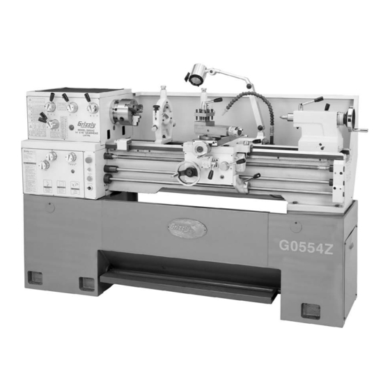
MODEL G0554Z
14" X 40" GEAR-HEAD
FLOOR LATHE
OWNER'S MANuAL
Copyright © MAy, 2009 By grizzly industriAl, inC., rEVisEd July, 2010 (tr)
WARNiNG: NO pORTiON OF THiS MANuAL MAy bE REpRODucED iN ANy SHApE
OR FORM WiTHOuT THE WRiTTEN AppROvAL OF GRiZZLy iNDuSTRiAL, iNc.
(For ModEls MAnuFACturEd sinCE 1/09) #ts11209 printEd in ChinA
Advertisement
Table of Contents

Related Manuals for Grizzly G0554Z


Summary of Contents for Grizzly G0554Z
- Page 1 14" X 40" GEAR-HEAD FLOOR LATHE OWNER'S MANuAL Copyright © MAy, 2009 By grizzly industriAl, inC., rEVisEd July, 2010 (tr) WARNiNG: NO pORTiON OF THiS MANuAL MAy bE REpRODucED iN ANy SHApE OR FORM WiTHOuT THE WRiTTEN AppROvAL OF GRiZZLy iNDuSTRiAL, iNc.
- Page 2 This manual provides critical safety instructions on the proper setup, operation, maintenance, and service of this machine/tool. Save this document, refer to it often, and use it to instruct other operators. Failure to read, understand and follow the instructions in this manual may result in fire or serious personal injury—including amputation, electrocution, or death.
-
Page 3: Table Of Contents
... 10 unpacking ... 10 inventory ... 11 Cleanup ... 12 site Considerations ... 13 placing & Assembling lathe ... 14 Mounting to shop Floor ... 16 Checking gear oil ... 16 test run ... 16 spindle Break-in ... 19 recommended Adjustments ... -
Page 4: Introduction
Machine For your convenience, we post all available man- uals and manual updates for free on our website at www.grizzly.com. Any updates to your model of machine will be reflected in these documents as soon as they are complete. -
Page 5: Identification
Work light G. Follow rest H. Coolant nozzle Compound slide Model g0554z (Mfg 01/09+) identification Figure 1. Model g0554z identification. tailstock (refer to Tailstock controls on page 23 for details) K. Carriage rack longitudinal leadscrew M. Feed rod N. spindle Control rod O. -
Page 6: Machine Data Sheet
Machine Data Sheet Customer Service #: (570) 546-9663 · To Order Call: (800) 523-4777 · Fax #: (800) 438-5901 MODEL G0554Z 14" X 40" GEAR-HEAD FLOOR LATHE Product Dimensions: Weight... 2750 lbs. Length/Width/Height... 75 x 28 x 46 in. Foot Print (Length/Width)... 74-1/2 x 19-1/4 in. - Page 7 The information contained herein is deemed accurate as of 1/3/2011 and represents our most recent product specifications. Model G0554Z Due to our ongoing improvement efforts, this information may not accurately describe items previously purchased. Model g0554z (Mfg 01/09+) PAGE 2 OF 3...
-
Page 8: Section 1: Safety
Extended exposure to this noise without hearing protection can cause permanent hearing loss. MENTAL ALERTNESS. Be mentally alert when running machinery. Never operate under the influence of drugs or alcohol, when tired, or when distracted. Model g0554z (Mfg 01/09+) - Page 9 Keep work area clean, dry, and well lighted to mini- mize risk of injury. Model g0554z (Mfg 01/09+) APPROVED OPERATION. Untrained operators can be seriously hurt by machinery. Only allow trained or properly supervised people to use machine.
-
Page 10: Additional Safety Instructions For Metal Lathes
Model g0554z (Mfg 01/09+) -
Page 11: Section 2: Circuit Requirements
Minimum Circuit size ... 20 Amps Model g0554z (Mfg 01/09+) Minimum cord Requirements use a stranded-copper flexible cord that meets the minimum requirements listed below, does not exceed 50 ft., and has an insulation type that... -
Page 12: Section 3: Setup
Wear safety glasses dur- ing the entire setup pro- cess! The Model G0554Z is a heavy machine. Serious personal injury may occur if safe moving methods are not used. To be safe, get assistance and use power equipment rated for at least 3500 lbs. -
Page 13: Inventory
Model g0554z (Mfg 01/09+) Figure 3. Model g0554z inventory 1. Figure 4. Model g0554z inventory 2. SuFFOcATiON HAZARD! immediately discard all plas-... -
Page 14: Cleanup
(Do not use a metal scraper or you may scratch your machine.) Repeat Steps 2–3 as necessary until clean, then coat all unpainted surfaces with a quality metal protectant to prevent rust. Model g0554z (Mfg 01/09+) inhaled. -
Page 15: Site Considerations
Only install in an access restricted location. 30" 38" Model g0554z (Mfg 01/09+) Physical Environment The physical environment where your machine is operated is important for safe operation and the longevity of its components. For best results,... -
Page 16: Placing & Assembling Lathe
& Assembling Lathe The Model G0554Z is a heavy machine. Serious personal injury may occur if safe moving methods are not used. To be safe, get assistance and use power equipment rated for at least 3500 lbs. to move the shipping crate and machine. - Page 17 Figure 10. Machine mounting holes. With assistance to balance the load, move it to the prepared location and lower it in place. Model g0554z (Mfg 01/09+) NOTICE For accurate turning results and to prevent cracking or warping of the cast iron bed and ways, the lathe MuST be made level from side-to-side and from front-to-back.
-
Page 18: Mounting To Shop Floor
Lubrication sec- tion on page 52 for detailed instructions. - Page 19 Center (neutral) position Figure 13. Carriage controls correctly setup for the Test Run. Model g0554z (Mfg 01/09+) push the emergency stop button in, then twist it clockwise until it pops out. When the emergency stop button pops out, the switch is reset and ready for operation (see Figures 14–15).
- Page 20 Call tech support for help. 20. Close the side door and secure it with the three cap screws. After successfully completing the Test Run pro- cedure, proceed to Spindle break-in. Model g0554z (Mfg 01/09+)
-
Page 21: Spindle Break-In
Make sure the carriage is disengaged from the leadscrew and feed rod (refer to Step 6 on page 17 for instructions). set the lathe to a spindle speed of 60 rpM (refer to Setting Spindle Speed on page 38 for detailed instructions). -
Page 22: Section 4: Operations
OMMEND that you read books, trade maga- zines, or get formal training before begin- ning any projects. Regardless of the con- tent in this section, Grizzly industrial will not be held liable for accidents caused by lack of training. NOTICE... -
Page 23: Basic Controls
Model g0554z (Mfg 01/09+) Headstock controls Figure 18. headstock controls. A. Feed Rate & Thread charts: show the con-... -
Page 24: Gearbox Controls
R. Half-Nut Lever: Engages the half-nut for longitudinal power feed and threading opera- tions. S. Spindle Lever: starts, stops, and reverses direction of spindle rotation. power Feed Lever: Engages the power feed for longitudinal or cross travel. Figure 20. Carriage controls. Model g0554z (Mfg 01/09+) -
Page 25: Tailstock Controls
Slide: Moves back-and-forth across the spindle center line and supports the com- pound rest. Model g0554z (Mfg 01/09+) Tailstock controls Figure 21. tailstock controls. Quill Handwheel: Moves the quill toward or away from the spindle. -
Page 26: Chuck & Faceplate Mounting
Foot brake the Model g0554z lathe comes equipped with a foot brake (see Figure 22). the foot brake is intended to be used primarily as a time saving tool. the best method for using the foot brake is to turn the spindle OFF with the spindle lever, then apply even and moderate pressure to the foot brake to slow the spindle to a stop. -
Page 27: Mounting Chuck Or Faceplate
Cam-lock stud Figure 25. Example of removing the 3-jaw chuck from the spindle nose. Model g0554z (Mfg 01/09+) Mounting chuck or Faceplate disConnECt lAthE FroM poWEr! lay a chuck cradle or a protective layer of plywood under the chuck or faceplate and... -
Page 28: 3-Jaw Chuck
Wrench 8mm ... 1 To reverse the jaw: disConnECt lAthE FroM poWEr! remove the two cap screws that secure each top jaw, as shown in Figure 29, then remove the top jaw. Figure 29. loosening the jaw cap screws. Model g0554z (Mfg 01/09+) -
Page 29: Mounting Workpiece
FroM poWEr! place the piece of plywood on the bedway below the chuck to protect it. Model g0554z (Mfg 01/09+) use the chuck key to open the jaws so that the workpiece lays flat against the chuck face, jaw steps, or fits into the spindle hole. -
Page 30: 4-Jaw Chuck
(see Figure 33 for an example). Figure 33. non-concentric workpiece correctly mounted on the 4-jaw chuck. Workpiece Center Point Model g0554z (Mfg 01/09+) -
Page 31: Faceplate
Failure to heed this warning could lead to serious personal injury, death or property damage. Model g0554z (Mfg 01/09+) With assistance, place the workpiece onto the faceplate and clamp it in place with a min- imum of three independent clamping devices (see Figure 34 for an example). -
Page 32: Centers
Dead center in Spindle When mounting the workpiece between cen- ters, install a lathe dog on the spindle end of the workpiece and insert the tail of the dog into the chuck or faceplate to keep the workpiece and center rotating together during operation (see Figure 36 for an example). - Page 33 Model g0554z (Mfg 01/09+) using a center in the Tailstock When mounting long, slender workpieces that extend more than 2 ⁄...
-
Page 34: Offsetting Tailstock
Alternately loosen and tighten the set screws on either side of the tailstock until the desired offset is indicated on the offset scale (see Figure 38). set screw (1 of 2) Figure 38. tailstock offset controls. Model g0554z (Mfg 01/09+) offset scale... -
Page 35: Tailstock Alignment
60° point, as shown in Figure 39. Figure 39. turning a dead center. Model g0554z (Mfg 01/09+) Note: As long as this dead center remains in the chuck, the point of the center will remain true to the spindle center line. -
Page 36: Drilling With Tailstock
Figure 43. inserting an Mt#3 drill chuck into the tailstock quill. Figure 44. inserting an Mt#3 drill shank into the tailstock quill. Model g0554z (Mfg 01/09+) -
Page 37: Coolant System
Coolant pump switch Figure 45. Coolant system controls and components. Model g0554z (Mfg 01/09+) Running the coolant pump without ade- quate coolant in the coolant reservoir may permanently damage the coolant system on your lathe. This action is considered abuse and is not covered by the warrant. -
Page 38: Steady Rest
Lubricate the finger tips with an anti-seize grease during operation. lock nut After prolonged use, the fingers will show wear. Either mill or file the tips for a new con- tact surface. rest. Model g0554z (Mfg 01/09+) -
Page 39: Follow Rest
Model g0554z as a guide to help judge when to stop the carriage movement. Tools Needed hex Wrench 5mm ... -
Page 40: Four-Way Tool Post
For carbide cutting tools, double the aver- age speed. These values are a guideline only. Refer to the MACHINERY’S HANDBOOK for more detailed information. Figure 51. Cutting speed table. NOTICE Average Tool Speed (sfm) Rough Cuts Finish Cuts Model g0554z (Mfg 01/09+) - Page 41 480 / 1" (diameter of workpiece) = 480 Result: the correct spindle speed is 480 rpM. Model g0554z (Mfg 01/09+) Examine the chart in Figure 52 or on the front of the headstock to determine the avail- able spindle speed closest to your calculated speed.
-
Page 42: Power Feed
Feed power feed on the Model g0554z uses the machine to move the tooling rather than manual rotation of the handwheels. When the feed rod is engaged, the carriage or cross slide moves. threading operations use powered rotation of the longitudinal leadscrew with the half-nut engaged. - Page 43 A–B Feed rate lever Column C–F Feed rate Knob Column A–B Feed rate lever Column Figure 55. Model g0544z feed rate and threading configuration charts. Model g0554z (Mfg 01/09+) 1 2 3 4 5 6 7 8 ⁄ ⁄ ⁄ .0294 .0261 .0235...
- Page 44 0.0082 ipr (inches per spindle revolution). to set the lathe up for this task, you will need to: set the spindle speed that is correct for this feed rate.
- Page 45 Figure 55 on page 41 or on the front of the headstock to determine the con- figuration for the feed rate lever and knobs. Model g0554z (Mfg 01/09+) set the feed rate lever and knobs as directed in the charts.
-
Page 46: Quick Change Gears
Model g0554z lathe ships with the 25t installed in the top position, the 120t/127t in the middle position, and the 50t installed in the bot- tom position, as shown in Figure 60. this configu- ration of gears will cover most feed rates and inch threading. - Page 47 To engage the power feed for non-threading operations: Make sure the spindle is OFF and has come to a complete stop. Model g0554z (Mfg 01/09+) use the power feed direction lever to select the rotation direction of the feed rod (see the illustration in Figure 61).
-
Page 48: Threading Controls
projects. - Page 49 5-1/2 6-1/2 1-1/2 5-3/4 Figure 65. Model g0554z thread dial chart. Model g0554z (Mfg 01/09+) For example, to cut a tpi of 11, engage the half- nut when the thread dial points to any number between 1 and 4. to cut a tpi of 4 half-nut on 1 or 3.
-
Page 50: Section 5: Accessories
ACCEssoriEs SEcTiON 5: AccESSORiES T10096—Taper Attachment for Model G0554Z H5948—collet Attachment for Model G0554Z H8257—primrose Armor plate with Moly-D Machine and Way Oil 1 Quart this superior machine and way lubricant prevents stick slip and chatter due to anti-friction capa- bilities resulting in greater precision machining capabilities. - Page 51 A "must have" reference for all metal lathe owners. 260 pages. Figure 71. h6879 lathe operation & Maintenance Book. Model g0554z (Mfg 01/09+) G0688—Tool post Grinder this tool post grinder has what it takes to make your project to spec and look good, too! the...
-
Page 52: Section 6: Maintenance
Make sure the bedways are level from side- to-side and front-to-back (page 15). cleaning & protecting Cleaning the Model g0554z is relatively easy. Vacuum excess metal chips, then wipe off built- up grime. protect the unpainted metal surfaces with regular applications of products such as... -
Page 53: Lubrication
Model g0554z (Mfg 01/09+) Figure 74. location of the nine ball oilers on the disconnect Figure 75. tailstock and leadscrew/feed rod... - Page 54 Figure 79. headstock drain plug, and gearbox fill and drain plugs. Apron Fill plug Apron drain plug Figure 80. Apron fill plug, sight glass, and drain plug. Model g0554z (Mfg 01/09+) gearbox Fill plug Apron sight glass...
-
Page 55: Tensioning/Replacing V-Belts
& Bolts Motor Mounting plate Figure 81. Motor adjustment hex nuts and bolts. Model g0554z (Mfg 01/09+) Check the deflection of the V-belts by apply- ing moderate pressure midway between the pulleys, as illustrated in Figure 82. When... -
Page 56: Checking/Cleaning Coolant System
Always use non-flammable water-based coolant to avoid explosions when the fluid comes in contact with hot metal chips from the milling operation. For best results, always follow the coolant manufacturer's recom- mendations for coolant/water ratios. drain Chute Model g0554z (Mfg 01/09+) - Page 57 Follow Federal, State, and the coolant manu- facturer's requirements to properly dispose of used coolant. Model g0554z (Mfg 01/09+) cleaning coolant Tank the coolant tank of your lathe holds approximately three gallons of coolant. replace the coolant every 30 days or sooner if it gives off a foul odor, which is due to the growth of dangerous microbes.
-
Page 58: Section 7: Service
2. refer to rpM feed rate chart for appropriate rates. 3. sharpen or replace the cutting tool. 4. re-adjust the quick change gear setup with a small amount of backlash so the gears move freely and smoothly when the spindle is rotated by hand. Model g0554z (Mfg 01/09+) - Page 59 1. Quill lock lever is tightened. not feed out of tailstock. Model g0554z (Mfg 01/09+) possible solution 1. Adjust for proper spindle speed and feed rate. 2. use sharp tools; use correct tool for the operation. 3. reduce depth of cut and take more passes.
-
Page 60: Cross Slide Backlash Adjustment
-58- Gib Adjustments the Model g0554z has four gib adjustments: the cross slide gib, the compound gib, the saddle gib, and the tailstock gib. When adjusting gibs, the goal is to remove unnec- essary sloppiness from the movement of the slid- ing surfaces without causing them to bind. -
Page 61: Tailstock Lock Adjustment
Step 4 until you are satisfied with the results, then re-tighten the hex nuts without moving the set screws. Model g0554z (Mfg 01/09+) Tailstock Gib the tailstock gib is adjusted in the same man- ner as the cross and compound slide gibs (see Figure 89). -
Page 62: Shear Pin Replacement
Note: Keep in mind that the shear pin hole is tapered and must be properly aligned to accept a new tapered shear pin. re-install a new tapered shear pin. re-install the leadscrew end bracket Model g0554z (Mfg 01/09+) -
Page 63: Brake Pads
Figure 92. top pulley Cap screw Figure 92. top pulley and cap screw. Model g0554z (Mfg 01/09+) step off the foot brake to release the brakes, then remove the pulley to expose the brake pads, as shown in Figure 93. -
Page 64: Spindle Bearing Preload
Figure 95. Note: Record the orientation of the oil drain chute on the inside of the end cap so that you can properly re-install the cap later. spindle nut Figure 95. spindle nut exposed. Model g0554z (Mfg 01/09+) - Page 65 Figure 96. introducing detectable spindle end- play. Model g0554z (Mfg 01/09+) 10. place a dial indicator on the cross slide and move the carriage toward the spindle until the contact point of the indicator just touches the spindle face, then zero out the dial, as shown in Figure 97.
-
Page 66: Gap Removal
⁄ -64- Gap Removal the Model g0554z comes equipped with a gap section below the spindle that can be removed for turning large diameter parts or when using a large diameter faceplate. the gap is installed, then ground at the factory during lathe assembly for precise fit and align- ment. -
Page 67: Section 8: Wiring
You can view these pages in color at www.grizzly.com. Model g0554z (Mfg 01/09+) MODiFicATiONS. using aftermarket parts or modifying the wiring beyond what is shown in the diagram may lead to unpredictable results, including serious injury or fire. -
Page 68: Electrical Overview
Electrical Cabinet Side Door Safety left rear View Switch Main Power Switch Brake Switch Motor Electrical Box (page 68) Main power switch (page 69) power Junction Box (page 70) 220V single- phase power source (page 70) Model g0554z (Mfg 01/09+) -
Page 69: Electrical Cabinet Identification
Electrical cabinet identification Fuses Contactor Contactor Contactor Contactor overload relays relay transformer grounding plate terminal Block Figure 100. Electrical cabinet identification. READ ELECTRICAL SAFETY -67- Model g0554z (Mfg 01/09+) ON PAGE 65! -
Page 70: Electrical Cabinet Wiring Diagram
Electrical cabinet Wiring Diagram Fuse Fuse READ ELECTRICAL SAFETY -68- ON PAGE 65! 500VAC 2MFD Capacitor Model g0554z (Mfg 01/09+) -
Page 71: Electrical Components (A)
Figure 101. halogen lamp. side door safety switch Figure 102. side door safety switch. Main power switch Figure 103. Main power switch. Model g0554z (Mfg 01/09+) Halogen Lamp Electrical Cabinet (page 68) Side Door Safety Switch Electrical Cabinet (page 68) Main Power Switch... -
Page 72: Electrical Components (B)
READ ELECTRICAL SAFETY -70- ON PAGE 65! Brake Switch Electrical Cabinet (page 68) Electrical Cabinet (page 68) Motor Power Junction Box Power Source 220V Single-Phase NEMA 6-20 Plug (As Recommended) (Not Included) Model g0554z (Mfg 01/09+) Main power switch (page 69) -
Page 73: Electrical Components (C)
Figure 107. Coolant pump. Control panel (viewed from rear) spindle switches Figure 108. spindle switches and control panel (viewed from the rear). Model g0554z (Mfg 01/09+) Coolant Pump Electrical Cabinet (page 68) Spindle Switches Electrical Cabinet (page 68) Control Panel... -
Page 74: Section 9: Parts
SEcTiON 9: pARTS Headstock Shifting breakdown 30 21 52 53 -72- 57 58 21 22 Model g0554z (Mfg 01/09+) - Page 75 PHLP HD SCR M3-.5 X 6 P0554Z0028 HUB SCREW PFH02M FLAT HD SCR M6-1 X 12 P0554Z0030 END CAP P5960083 O-RING 19 X 2.65 Model g0554z (Mfg 01/09+) REF PART # DESCRIPTION P0554Z0032 GEAR SHAFT 22T P0554Z0033 GEAR SHAFT 17T P0554Z0034 END CAP...
-
Page 76: Headstock Gearing
Headstock Gearing breakdown -74- Left Side Profile Model g0554z (Mfg 01/09+) - Page 77 GEAR 43T P0554Z0082 BALL BEARING 6204/P5 P0554Z0083 SPACER P0554Z0084 GEAR 57T P0554Z0085 GEAR SHAFT 20T PR25M INT RETAINING RING 47MM Model g0554z (Mfg 01/09+) REF PART # DESCRIPTION P0554Z0087 O-RING 40 X 2.65 P0554Z0088 CASTING PLUG P0554Z0089 END CAP P0554Z0090 GASKET...
-
Page 78: Headstock Spindle
Headstock Spindle breakdown -76- 149 133 Model g0554z (Mfg 01/09+) - Page 79 CAP SCREW M6-1 X 25 PK42M KEY 6 X 6 X 30 PK123M KEY 10 X 10 X 55 PSB27M CAP SCREW M6-1 X 14 P0554Z0129 COMPRESSION SPRING Model g0554z (Mfg 01/09+) REF PART # DESCRIPTION P0554Z0130 BEVELED PIN P0554Z0131 CAMLOCK P0554Z0132 SPINDLE...
-
Page 80: Gearbox Shifting
Gearbox Shifting breakdown -78- 223 241 Model g0554z (Mfg 01/09+) - Page 81 P0554Z0229 SHAFT P0554Z0230 LOCATING PLATE P0554Z0231 CONTROL PLATE PSB26M CAP SCREW M6-1 X 12 P0554Z0233 OIL FILL PLUG Model g0554z (Mfg 01/09+) REF PART # DESCRIPTION P0554Z0234 SHIFT HUB PK05M KEY 4 X 4 X 10 P0554Z0236 SHAFT P0554Z0238 GEAR SHAFT 26T...
-
Page 82: Gearbox Gearing
Gearbox Gearing breakdown -80- Model g0554z (Mfg 01/09+) - Page 83 P0554Z0288 GEAR WASHER P0554Z0289 GEAR 22T P0554Z0290 GEAR WASHER P0554Z0291 GEAR 20T P0554Z0292 GEAR WASHER P0554Z0293 GEAR 18T Model g0554z (Mfg 01/09+) REF PART # DESCRIPTION P0554Z0294 GEAR WASHER P0554Z0295 GEAR 16T P0554Z0296 GEAR 26T P0554Z0297 SPLINE SHAFT PK19M KEY 5 X 5 X 14...
-
Page 84: Apron Controls
HANDLE LEVER CAP SCREW M6-1 X 45 PLUG CAP SCREW M6-1 X 16 OIL DRAIN PLUG END CAP KEY 5 X 5 X 56 PIN 3 X 5 WORM LOCK COLLAR SET SCREW M5-.8 X 10 Model g0554z (Mfg 01/09+) -
Page 85: Apron Gearing
P0554Z0449 SLEEVE P0554Z0450 CLUSTER GEAR 50T/20T PSS20M SET SCREW M8-1.25 X 8 P0554Z0452 COMPRESSION SPRING P0554Z0410 STEEL BALL 6MM P0554Z0454 SHAFT Model g0554z (Mfg 01/09+) Apron Gearing REF PART # P0554Z0455 P0554Z0456 P0554Z0457 P0554Z0458 PR06M P0554Z0460 P0554Z0461 PK20M P0554Z0463 PSB01M... -
Page 86: Saddle & Cross Slide
Saddle & cross Slide breakdown Cross slide Backlash Adjustment Cap screw -84- 553 554 Model g0554z (Mfg 01/09+) - Page 87 P0554Z0528 INDEX PLATE P0554Z0529 BEARING HOUSING PSB29M CAP SCREW M6-1 X 40 P8102 THRUST BEARING 8102 P0554Z0532 END CAP Model g0554z (Mfg 01/09+) REF PART # DESCRIPTION PS09M PHLP HD SCR M5-.8 X 10 P0554Z0534 GRADUATED DIAL P0554Z0535 HANDWHEEL P0554Z0536...
-
Page 88: Compound Slide & Tool Post
HANDWHEEL SCREW SET SCREW M6-1 X 25 CAP SCREW M5-.8 X 40 HANDLE STEEL BALL 6MM COMPRESSION SPRING SET SCREW M6-1 X 16 GIB ADJUSTMENT SCREW COMPOUND SLIDE GIB HEX NUT M8-1.25 SWIVEL SLIDE FLAT WASHER 8MM Model g0554z (Mfg 01/09+) -
Page 89: Tailstock
TAILSTOCK CASTING P0554Z0410 STEEL BALL 6MM P0554Z0666 COMPRESSION SPRING P0554Z0667 HANDWHEEL PSS28M SET SCREW M6-1 X 30 P0554Z0669 HANDWHEEL SCREW P0554Z0670 HANDLE SCREW Model g0554z (Mfg 01/09+) Tailstock REF PART # P0554Z0671 PSB128M P0554Z0673 P0554Z0674 PB140M PW06M P0554Z0677 P0554Z0678 P0554Z0679 PN02M... -
Page 90: Follow Rest
CAP SCREW M6-1 X 45 -88- REF PART # P0554Z0751 P0554Z0752 P0554Z0753 P0554Z0754 P0554Z0755 P0554Z0756 PSB30M Thread Dial DESCRIPTION DIAL PIN 3 X 12 SHAFT PIN 3 X 20 GEAR 32T THREAD DIAL BODY CAP SCREW M6-1 X 45 Model g0554z (Mfg 01/09+) -
Page 91: Steady Rest
P0554Z0706 BRASS FINGER P0554Z0807 UPPER STEADY REST CASTING P0554Z0808 PIN 8 X 40 PSS25M SET SCREW M6-1 X 20 PN01M HEX NUT M6-1 Model g0554z (Mfg 01/09+) Steady Rest REF PART # P0554Z0811 P0554Z0812 PN09M PW06M P0554Z0815 PW06M PB141M P0554Z0818... -
Page 92: Change & End Gears
GEAR 32T GEAR 40T FRONT COVER CAP SCREW M6-1 X 20 DOOR BRACKET PIN 6 X 25 UPPER HINGE HINGE PIN LOWER HINGE SIDE DOOR CAP SCREW M5-.8 X 10 BRACKET PHLP HD SCR M6-1 X 8 Model g0554z (Mfg 01/09+) -
Page 93: Bed & Shaft
& Shaft breakdown -91- Model g0554z (Mfg 01/09+) - Page 94 P0554Z0953 STOP STUD M12-1.75 X 40 P0554Z0954 GRADUATED DIAL P0554Z0955 PIN 3 X 6 P0554Z0956 SHAFT P0554Z0957 BRACKET PSS01M SET SCREW M6-1 X 10 P0554Z0959 CLAMP PLATE PSB02M CAP SCREW M6-1 X 20 P0554Z0961 SHEAR PIN 5 X 40 Model g0554z (Mfg 01/09+)
-
Page 95: Stand & Brake
1023 1024 1039 1056 1038 1037 1026 1027 1028 1029 1036 1035 1030 1031 1034 1032 1033 1025 1002 Model g0554z (Mfg 01/09+) 1003 1001 1007 1008 1011 1010 1002 1045 1044 1048 1043 1042 1040 1041 1002 1057 1058... - Page 96 KILL SWITCH 1057 P0554Z1057 HALOGEN LAMP ASSEMBLY 1058 PS15M PHLP HD SCR M6-1 X 14 1059 PSB31M CAP SCREW M8-1.25 X 25 1060 P0554Z1060 COOLANT NOZZLE 1061 P0554Z1061 COOLANT ON/OFF VALVE 1062 P0554Z1062 COOLANT TANK HOSE Model g0554z (Mfg 01/09+)
-
Page 97: Electrical
Electrical breakdown 1106 1107 1108 1053 1053-1 1053-5 1053-2 1053-4 1053-3 1054 1126 1113 1114 1128 Model g0554z (Mfg 01/09+) 1101 1102 17.6A 1122 1121 1109 1110 1111 1118 1053-6 1057-6 1112 1115 1116 1125 1124 1129 1127 1123 1103... - Page 98 MAIN POWER SWITCH 1124 P0554Z1124 MAIN POWER SWITCH CORD 1125 P0554Z1125 POWER TERMINAL BOX 1126 P0554Z1126 POWER TERMINAL BOX COVER 1127 P0554Z1127 TERMINAL BLOCK 8-POST 1128 P0554Z1128 PHLP HD SCR M8-1.25 X 25 1129 P0554Z1129 POWER CORD Model g0554z (Mfg 01/09+)
-
Page 99: Accessories
1211 P0554Z1211 WRENCH 9/11 1212 PWR1012 WRENCH 10/12 1213 PWR1214 WRENCH 12/14 1214 PWR1417 WRENCH 14/17 1215 P0554Z1215 SPINDLE LOCK KEY Model g0554z (Mfg 01/09+) Accessories 1202 1205 1206 1209 1210 1217 1233 1227 1230 1228 1229 PART # 1217... -
Page 100: Label Placement
MuST maintain the original location and readability of the labels on the machine. if any label is removed or becomes unreadable, REpLAcE that label before using the machine again. contact Grizzly at (800) 523-4777 or www.grizzly.com to order new labels. -98-... -
Page 101: Warranty Card
Do you think your machine represents a good value? Would you recommend Grizzly Industrial to a friend? Would you allow us to use your name as a reference for Grizzly customers in your area? Note: We never use names more than 3 times. - Page 102 FOLD ALONG DOTTED LINE FOLD ALONG DOTTED LINE Send a Grizzly Catalog to a friend: Name_______________________________ Street_______________________________ City______________State______Zip______ GRIZZLY INDUSTRIAL, INC. P.O. BOX 2069 BELLINGHAM, WA 98227-2069 TAPE ALONG EDGES--PLEASE DO NOT STAPLE Place Stamp Here...
-
Page 103: Warranty And Returns
WARRANTY AND RETURNS Grizzly Industrial, Inc. warrants every product it sells for a period of 1 year to the original purchaser from the date of purchase. This warranty does not apply to defects due directly or indirectly to misuse, abuse, negligence, accidents, repairs or alterations or lack of maintenance. - Page 104 Buy Direct and Save with Grizzly – Trusted, Proven and a Great Value! ® ~Since 1983~ Visit Our Website Today For Current Specials! ORDER 24 HOURS A DAY! 1-800-523-4777...