Table of Contents
Advertisement
Quick Links
Download this manual
See also:
Manual
GA-8I955X Royal/
GA-8I955X Pro
Intel
Pentium
®
®
Intel
Pentium
®
®
User's Manual
Rev. 1105
12ME-8I955XRO-1105
* The WEEE marking on the product indicates this product must not be disposed of with user's other household waste
and must be handed over to a designated collection point for the recycling of waste electrical and electronic equipment!!
* The WEEE marking applies only in European Union's member states.
Processor Extreme Edition
D / Pentium
4 LGA775 Processor Motherboard
®
Advertisement
Table of Contents

Related Manuals for Gigabyte GA-8I955X Pro


Summary of Contents for Gigabyte GA-8I955X Pro
- Page 1 GA-8I955X Royal/ GA-8I955X Pro Intel Pentium Processor Extreme Edition ® ® Intel Pentium D / Pentium 4 LGA775 Processor Motherboard ® ® ® User's Manual Rev. 1105 12ME-8I955XRO-1105 * The WEEE marking on the product indicates this product must not be disposed of with user's other household waste and must be handed over to a designated collection point for the recycling of waste electrical and electronic equipment!! * The WEEE marking applies only in European Union's member states.
- Page 4 Gigabyte's prior written permission. Specifications and features are subject to change without prior notice. Product Manual Classification In order to assist in the use of this product, Gigabyte has categorized the user manual in the following: For quick installation, please refer to the "Hardware Installation Guide" included with the product.
-
Page 5: Table Of Contents
Table of Contents GA-8I955X Royal/GA-8I955X Pro Motherboard Layout ..........7 Block Diagram ........................ 8 Chapter 1 Hardware Installation ..................9 Considerations Prior to Installation ..............9 Feature Summary ..................10 Installation of the CPU and Heatsink .............. 12 1-3-1 Installation of the CPU ..................12 1-3-2 Installation of the Heatsink .................. - Page 6 Chapter 3 Drivers Installation ..................49 Install Chipset Drivers ..................49 Software Applications ..................50 Driver CD Information ..................50 Hardware Information ..................51 Contact Us ..................... 51 Chapter 4 Appendix ....................53 Unique Software Utilities ................53 4-1-1 EasyTune 5 Introduction ..................54 4-1-2 Xpress Recovery2 Introduction .................
-
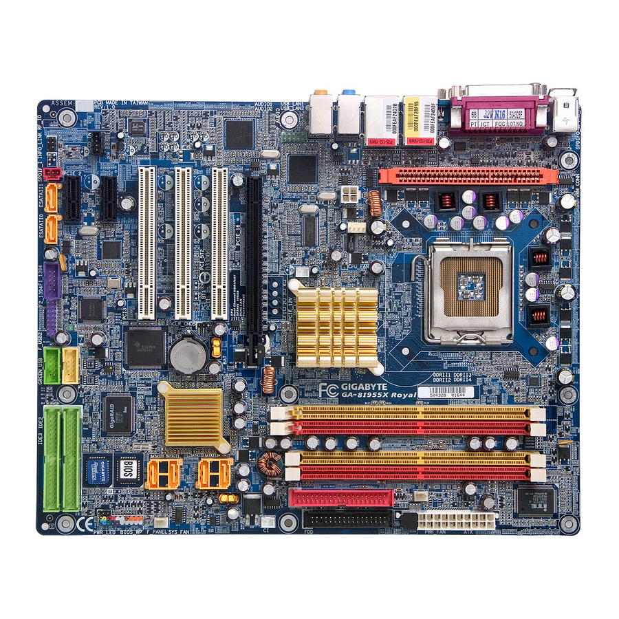
Page 7: Ga-8I955X Royal/Ga-8I955X Pro Motherboard Layout
GA-8I955X Royal/GA-8I955X Pro Motherboard Layout CPU_FAN IT8712F KB_MS VRM_CONN SPDIF_O SPDIFO_OPT LGA775 ATX_12V_2X4 AUDIO1 Intel ® 955X AUDIO2 NB_FAN Broadcom 5751 phy IDE1 F_AUDIO PCIE_16 Broadcom 5751 / 5789 phy SATAII3 PCI1 SATAII2 Intel ® CLR_CMOS PCI2 ICH7R BATTERY SATAII1... -
Page 8: Block Diagram
PCICLK(33MHz) (Note 1) DDR II memory can be overclocked to 888MHz (must be used with a 1066MHz FSB processor) through overclocking in BIOS. Go to GIGABYTE's website for more information about the supported DDR II memory modules for this feature. -
Page 9: Chapter 1 Hardware Installation
2. Damage as a result of violating the conditions recommended in the user manual. 3. Damage due to improper installation. 4. Damage due to use of uncertified components. 5. Damage due to use exceeding the permitted parameters. 6. Product determined to be an unofficial Gigabyte product. - 9 - Hardware Installation... -
Page 10: Feature Summary
Out (Rear Speaker Out) ; Center/Subwoofer Speaker Out ; Side Speaker Out connection (Note 1) For further CPU support information, please go to GIGABYTE's website. (Note 2) Due to standard PC architecture, a certain amount of memory is reserved for system usage and therefore the actual memory size is less than the stated amount. - Page 11 Over Voltage via BIOS (FSB/DDR II/PCIE/CPU) Over Clock via BIOS (CPU/DDR II/PCIE) Form Factor ATX form factor; 30.5cm x 24.4cm (Note 6) EasyTune 5 functions may vary depending on different motherboards. Only for GA-8I955X Royal. Only for GA-8I955X Pro. - 11 - Hardware Installation...
-
Page 12: Installation Of The Cpu And Heatsink
(Grasping the CPU firmly between your thumb and forefinger, carefully place it into the socket in a straight and downwards motion. Avoid twisting or bending motions that might cause damage to the CPU during installation.) GA-8I955X Royal/GA-8I955X Pro Motherboard - 12 -... -
Page 13: Installation Of The Heatsink
1-3-2 Installation of the Heatsink Male Push Pin The top of Female Push Pin Female Push Pin Fig.1 Fig. 2 Please apply an even layer of heatsink paste on (Turning the push pin along the direction of arrow is the surface of the installed CPU. to remove the heatsink, on the contrary, is to install.) Please note the direction of arrow sign on the male push pin doesn't face inwards before installation. -
Page 14: Installing/Removing Cool-Plus (Northbridge Cooling Fan)
The motherboard supports DDR II memory modules, whereby BIOS will automatically detect memory capacity and specifications. Memory modules are designed so that they can be inserted only in one direction. The memory capacity used can differ with each slot. Notch DDR II GA-8I955X Royal/GA-8I955X Pro Motherboard - 14 -... - Page 15 Fig.1 The DIMM socket has a notch, so the DIMM memory module can only fit in one direction. Insert the DIMM memory module vertically into the DIMM socket. Then push it down. Fig.2 Close the plastic clip at both edges of the DIMM sockets to lock the DIMM module.
-
Page 16: Installation Of Expansion Cards
PCI Express x 16 slot. When you try uninstall the VGA card, please gently press the latch as the picture to the left shows to release the card. GA-8I955X Royal/GA-8I955X Pro Motherboard - 16 -... -
Page 17: Installation Of U-Plus Dps (Universal Plus Dual Power System)
Installation of U-Plus DPS (Universal Plus Dual Power System) The U-Plus Dual Power System (U-Plus D.P.S.) is a revolutionary eight-phase power circuit built for ultimate system protection. Designed to withstand varying current levels and changes, the U-Plus DPS provides an immensely durable and stable power circuit to the CPU for solid system stability. These characteristics make it the ideal companion with the latest LGA775 Intel Pentium 4 Processor as well... -
Page 18: I/O Back Panel Introduction
Surround Speaker Out (Rear Speaker Out) The default Surround Speaker Out (Rear Speaker Out) jack. Rear surround speakers can be connected to Surround Speaker Out (Rear Speaker Out) jack. Only for GA-8I955X Royal. GA-8I955X Royal/GA-8I955X Pro Motherboard - 18 -... -
Page 19: Connectors Introduction
Center/Subwoofer Speaker Out The default Center/Subwoofer Speaker Out jack. Center/Subwoofer speakers can be connected to Center/Subwoofer Speaker Out jack. Side Speaker Out The default Side Speaker Out jack. Surround side speakers can be connected to Side Speaker Out jack. In addition to the default speakers settings, the audio jacks can be reconfigured to perform different functions via the audio software. - Page 20 Pin No. Definition 3.3V 3.3V 3.3V -12V PS_ON(soft On/Off) Power Good 5V SB(stand by +5V) +12V +12V(Only for 24-pin ATX) +5V (Only for 24-pin ATX) 3.3V(Only for 24-pin ATX) GND(Only for 24-pin ATX) GA-8I955X Royal/GA-8I955X Pro Motherboard - 20 -...
- Page 21 3/4/5) CPU_FAN / SYS_FAN/ PWR_FAN (Cooler Fan Power Connector) The cooler fan power connector supplies a +12V power voltage via a 3-pin/4-pin (only for CPU_FAN) power connector and possesses a foolproof connection design. Most coolers are designed with color-coded power connector wires. A red power connector wire indicates a positive connection and requires a +12V power voltage.
- Page 22 Master and the other as Slave (for information on settings, please refer to the instructions located on the IDE device). To ensure that an IDE CD-ROM drive can work properly, please attach it to the IDE 1 connector. IDE1 IDE2/3 GA-8I955X Royal/GA-8I955X Pro Motherboard - 22 -...
-
Page 23: F_Panel (Front Panel Jumper)
9) SATAII0/1/2/3 (SATA 3Gb/s Connectors, Controlled by ICH7R) 10) ESATAII0/1 (SATA 3Gb/s Connectors, Controlled by Sil3132) SATA 3Gb/s can provide up to 300MB/s transfer rate. Please refer to the BIOS setting for the SATA 3Gb/s and install the proper driver in order to work properly. Pin No. -
Page 24: Front Audio Connector
Page 82 about the software settings. 13) CD_IN (CD IN) Connect CD-ROM or DVD-ROM audio out to the connector. Pin No. Definition CD-L CD-R GA-8I955X Royal/GA-8I955X Pro Motherboard - 24 -... - Page 25 14) SPDIF_I (SPDIF In) Use SPDIF IN feature only when your device has digital output function. Be careful with the polarity of the SPDIF_I connector. Check the pin assignment carefully while you connect the SPDIF cable, incorrect connection between the cable and connector will make the device unable to work or even damage it.
- Page 26 You may clear the CMOS data to its default values by this header. To clear CMOS, temporarily short 1-2 pin. Default doesn't include the jumper to prevent from improper use of this header. Open: Normal Short: Clear CMOS GA-8I955X Royal/GA-8I955X Pro Motherboard - 26 -...
- Page 27 18) RF_ID This connector allows you to connect external devices to use extra function. Check the pin assignments before you connect the external device cable. Please contact your nearest dealer for the optional GIGABYTE external device. Pin No. Definition Power...
- Page 28 (Or you can use a metal object to connect the positive and nega- tive pins in the battery holder to makethem short for one minute.) 3. Re-install the battery. 4. Plug the power cord and turn ON the computer. GA-8I955X Royal/GA-8I955X Pro Motherboard - 28 -...
-
Page 29: Chapter 2 Bios Setup
BIOS needs to be reset to its original settings. If you wish to upgrade to a new BIOS, either GIGABYTE's Q-Flash or @BIOS utility can be used. Q-Flash allows the user to quickly and easily update or backup BIOS without entering the operating system. -
Page 30: The Main Menu (For Example: Bios Ver. : Ga-8I955X Royal F6C)
This setup page is control CPU clock and frequency ratio. Select Language This setup page is to select multi languages. Load Fail-Safe Defaults Fail-Safe Defaults indicates the value of the system parameters which the system would be in safe configuration. GA-8I955X Royal/GA-8I955X Pro Motherboard - 30 -... - Page 31 Load Optimized Defaults Optimized Defaults indicates the value of the system parameters which the system would be in best performance configuration. Set Supervisor Password Change, set, or disable password. It allows you to limit access to the system and Setup, or just to Setup.
-
Page 32: Standard Cmos Features
Cylinder Number of cylinders Head Number of heads Precomp Write precomp Landing Zone Landing zone Sector Number of sectors If a hard disk has not been installed, select NONE and press <Enter>. GA-8I955X Royal/GA-8I955X Pro Motherboard - 32 -... - Page 33 Drive A / Drive B The category identifies the types of floppy disk drive A or drive B that has been installed in the computer. None No floppy drive installed. 360K, 5.25" 5.25 inch PC-type standard drive; 360K byte capacity. 1.2M, 5.25"...
-
Page 34: Advanced Bios Features
The system will not boot and will not access to Setup page if the correct password is not entered at the prompt. (Note) This item will show up when you install a processor that supports this function. GA-8I955X Royal/GA-8I955X Pro Motherboard - 34 -... - Page 35 CPU Hyper-Threading Enabled Enables CPU Hyper Threading Feature. Please note that this feature is only working for operating system with multi processors mode supported. (Default value) Disabled Disables CPU Hyper Threading. Limit CPUID Max. to 3 Enabled Limit CPUID Maximum value to 3 when use older OS like NT4. Disabled Disables CPUID Limit for windows XP.(Default value) No-Execute Memory Protect...
-
Page 36: Integrated Peripherals
Serial ATA features such as Native Command Queuing and hot plug. For more details about AHCI, please visit Intel's website. Disabled Set the onboard SATA controller to IDE mode. Only for GA-8I955X Royal. GA-8I955X Royal/GA-8I955X Pro Motherboard - 36 -... - Page 37 On-Chip SATA Mode Disabled Disable this function. Auto BIOS will detect automatically. (Default value) Combined Set On-Chip SATA mode to Combined, you can use up to 4 HDDs on the motherboard; 2 for SATA and the other for PATA IDE. Enhanced Set On-Chip SATA mode to Enhanced, the motherboard allows up to 6 HDDs to use.
- Page 38 ECP+EPP Using Parallel port as ECP & EPP mode. ECP Mode Use DMA Set ECP Mode Use DMA to 3. (Default value) Set ECP Mode Use DMA to 1. Only for GA-8I955X Royal. GA-8I955X Royal/GA-8I955X Pro Motherboard - 38 -...
-
Page 39: Power Management Setup
Power Management Setup CMOS Setup Utility-Copyright (C) 1984-2005 Award Software Power Management Setup ACPI Suspend Type [S1(POS)] Item Help Soft-Off by PWR-BTTN [Instant-Off] Menu Level PME Event Wake Up [Enabled] Power On by Ring [Enabled] [S1] Resume by Alarm [Disabled] Set suspend type to x Date (of Month) Alarm Everyday... -
Page 40: Pnp/Pci Configurations
Auto assign IRQ to PCI 2. (Default value) 3,4,5,7,9,10,11,12,14,15 Set IRQ 3,4,5,7,9,10,11,12,14,15 to PCI 2. PCI 3 IRQ Assignment Auto Auto assign IRQ to PCI 3. (Default value) 3,4,5,7,9,10,11,12,14,15 Set IRQ 3,4,5,7,9,10,11,12,14,15 to PCI 3. GA-8I955X Royal/GA-8I955X Pro Motherboard - 40 -... -
Page 41: Pc Health Status
PC Health Status CMOS Setup Utility-Copyright (C) 1984-2005 Award Software PC Health Status Reset Case Open Status [Disabled] Item Help Case Opened Menu Level Vcore DDRV +3.3V +12V Current CPU Temperature Current CPU FAN Speed 4687 RPM Current POWER FAN Speed Current SYSTEM FAN Speed CPU Warning Temperature [Disabled]... - Page 42 In fact, the Voltage option can be used for CPU fans with 3-pin or 4-pin power cables. However, some 4-pin CPU fan power cables are not designed following Intel 4-wire fans PWM control specifications. With such CPU fans, selecting PWM will not effectively reduce the fan speed. GA-8I955X Royal/GA-8I955X Pro Motherboard - 42 -...
-
Page 43: Mb Intelligent Tweaker(M.i.t.)
MB Intelligent Tweaker(M.I.T.) CMOS Setup Utility-Copyright (C) 1984-2005 Award Software MB Intelligent Tweaker(M.I.T.) C.A.M. (Note) [High] Item Help CPU Clock Ratio (Note) [15X] Menu Level Robust Graphics Booster [Auto] C.I.A. 2 [Disabled] CPU Adjustable Multipli CPU Host Clock Control [Disabled] x CPU Host Frequency(Mhz) x PCI Express Frequency(Mhz) Auto... - Page 44 Memory Frequency = Host clock X 3.33. 3.00 Memory Frequency = Host clock X 3.00. 4.00 Memory Frequency = Host clock X 4.00. Auto Set Memory frequency by DRAM SPD data. (Default value) GA-8I955X Royal/GA-8I955X Pro Motherboard - 44 -...
- Page 45 Memory Frequency (Mhz) The values depend on CPU Host Frequency(Mhz) and System Memory Multiplier setting. DIMM OverVoltage Control Normal Set DIMM OverVoltage Control to Normal. (Default value) +0.1V Set DIMM OverVoltage Control to +0.1V. +0.2V Set DIMM OverVoltage Control to +0.2V. +0.3V Set DIMM OverVoltage Control to +0.3V.
-
Page 46: Select Language
Esc: Quit F3: Change Language F8: Dual BIOS/Q-Flash F10: Save & Exit Setup Load Optimized Defaults Selecting this field loads the factory defaults for BIOS and Chipset Features which the system automati- cally detects. GA-8I955X Royal/GA-8I955X Pro Motherboard - 46 -... -
Page 47: Set Supervisor/User Password
2-11 Set Supervisor/User Password CMOS Setup Utility-Copyright (C) 1984-2005 Award Software Standard CMOS Features Select Language Advanced BIOS Features Load Fail-Safe Defaults Integrated Peripherals Load Optimized Defaults Power Management Setup Set Supervisor Password PnP/PCI Configurations Set User Password Enter Password: PC Health Status Save &... -
Page 48: Save & Exit Setup
F3: Change Language F8: Dual BIOS/Q-Flash F10: Save & Exit Setup Abandon all Data Type "Y" will quit the Setup Utility without saving to RTC CMOS. Type "N" will return to Setup Utility. GA-8I955X Royal/GA-8I955X Pro Motherboard - 48 -... -
Page 49: Chapter 3 Drivers Installation
Chapter 3 Drivers Installation Pictures below are shown in Windows XP. Insert the driver CD-title that came with your motherboard into your CD-ROM drive, the driver CD-title will auto start and show the installation guide. If not, please double click the CD-ROM device icon in "My computer", and execute the Run.exe. -
Page 50: Software Applications
Software Applications This page displays all the tools that Gigabyte developed and some free software, you can choose anyone you want and press "install" to install them. Driver CD Information This page lists the contents of software and drivers in this CD-title. -
Page 51: Hardware Information
Hardware Information This page lists all device you have for this motherboard. Contact Us Please see the last page for details. - 51 - Drivers Installation... - Page 52 GA-8I955X Royal/GA-8I955X Pro Motherboard - 52 -...
-
Page 53: Chapter 4 Appendix
Motherboard Intelligent Tweaker (M.I.T.) allows user to access and change BIOS feature settings with relative speed and ease. Through GIGABYTE M.I.T. feature the user is no longer required to switch into different modes within BIOS setup in order to change system settings such as the CPU system bus, memory timings or to enabled Gigabyte's unique C.I.A. -
Page 54: Easytune 5 Introduction
Toggles between Easy and Advance Mode Display screen Display panel of CPU frequency Function display LEDs Shows the current functions status GIGABYTE Logo Log on to GIGABYTE website Help button Display EasyTune 5 Help file Exit or Minimize button Quit or Minimize EasyTune... -
Page 55: Xpress Recovery2 Introduction
4-1-2 Xpress Recovery2 Introduction Xpress Recovery2 is designed to provide quick backup and restora- tion of hard disk data. Supporting Microsoft operating systems including Windows XP/2000/NT/98/Me and DOS, and file systems including FAT16, FAT32, and NTFS, Xpress Recovery2 is able to back up data on hard disks on PATA and SATA IDE controllers. - Page 56 (As this is a BIOS-related issue, it can be solved by BIOS update) GA-K8NXP-9 GA-8N-SLI Royal GA-K8U GA-K8N Ultra-9 GA-8N-SLI Pro GA-K8U-9 GA-K8NF-9 (PCB Ver. 1.0) GA-8N-SLI GA-K8NXP-SLI GA-K8NE (PCB Ver. 1.0) GA-K8N Ultra-SLI GA-K8NMF-9 GA-K8N Pro-SLI GA-8I955X Royal/GA-8I955X Pro Motherboard - 56 -...
-
Page 57: Flash Bios Method Introduction
4-1-3 Flash BIOS Method Introduction A. What is Dual BIOS Technology? Dual BIOS means that there are two system BIOS (ROM) on the motherboard, one is the Main BIOS and the other is Backup BIOS. Under the normal circumstances, the system works on the Main BIOS. If the Main BIOS is corrupted or damaged, the Backup BIOS can take over while the system is powered on. - Page 58 The means that the Backup BIOS works normally and could automatically recover the Main BIOS. (This auto recovery utility is set by system automatically and can’t be changed by user.) Load Default Settings Load dual BIOS default value. Save Settings to CMOS Save revised setting. GA-8I955X Royal/GA-8I955X Pro Motherboard - 58 -...
-
Page 59: Q-Flash Utility
Updating BIOS with Q-Flash Utility on Dual BIOS Motherboards. Some of Gigabyte motherboards are equipped with dual BIOS. In the BIOS menu of the motherboards supporting Q-Flash and Dual BIOS, the Q-Flash utility and Dual BIOS utility are combined in the same screen. - Page 60 Contains the names of four tasks. Blocking a task and pressing Enter key on your keyboard to enable execu- tion of the task. Action bar: Contains the names of four actions needed to operate the Q-Flash/Dual BIOS utility. Pressing the buttons mentioned on your keyboards to perform these actions. GA-8I955X Royal/GA-8I955X Pro Motherboard - 60 -...
- Page 61 Using the Q-Flash utility: This section tells you how to update BIOS using the Q-Flash utility. As described in the "Before you begin" section above, you must prepare a floppy disk having the BIOS file for your motherboard and insert it to your computer.
- Page 62 Primary Master : FUJITSU MPE3170AT ED-03-08 Primary Slave : None Secondary Master : CREATIVEDVD-RM DVD1242E BC101 Secondary Slave : None Press DEL to enter SETUP / Dual BIOS / Q-Flash / F9 For Xpress Recovery 09/23/2003-i875P-6A79BG03C-00 GA-8I955X Royal/GA-8I955X Pro Motherboard - 62 -...
- Page 63 Press Del to enter BIOS menu after system reboots. When you are in BIOS menu, move to Load Fail-Safe Defaults item and press Enter to load BIOS Fail-Safe Defaults. Normally the system redetects all devices after BIOS has been upgraded. Therefore, we highly recommend reloading the BIOS defaults after BIOS has been upgraded.
- Page 64 F10:Power Off After BIOS file is read, you'll see a confirmation dialog box asking you "Are you sure to update BIOS?" Please do not take out the floppy disk when it begins flashing BIOS. GA-8I955X Royal/GA-8I955X Pro Motherboard - 64 -...
- Page 65 Press Y button on your keyboard after you are sure to update BIOS. Then it will begin to update BIOS. The progress of updating BIOS will be shown at the same time. Q-Flash Utility V1.30 Flash Type/Size.........SST 49LF003A 256K Keep DMI Data Enable Do not trun off power or Updating BIOS Now...
-
Page 66: @Bios Utility
Please select "All Files" in dialog box while opening the old file. Please search for BIOS unzip file, downloading from internet or any other methods (such as: 8I955XRO.F1). Complete update process following the instruction. GA-8I955X Royal/GA-8I955X Pro Motherboard - 66 -... - Page 67 III. In method I, if the BIOS file you need cannot be found in @BIOS server, please go onto Gigabyte's web site for downloading and updating it according to method II. IV. Please note that any interruption during updating will cause system unbooted.
-
Page 68: Serial Ata Bios Setting Utility Introduction
After replacing the failed drive, you can rebuild the data from the remaining data and parity. Only one drive can be safely crash without any data loss. GA-8I955X Royal/GA-8I955X Pro Motherboard - 68 -... - Page 69 More information on steps 4 and 5 is provided. (For more detailed setup information, please visit "Support\ Motherboard\ Technology Guide section" on our website at http:\\www.gigabyte.com.tw to read or download the information you need.) Sections below introduce the steps to configure Intel and Promise RAID BIOS A.
- Page 70 ]-Change [TAB]-Next [ESC]-Previous Menu [ENTER]-Select There are four RAID levels: RAID0(Stripe), RAID1(Mirror), RAID 0+1 (Striping + Mirroring) and RAID5. After selecting the RAID level, press Enter to select Strip Size. GA-8I955X Royal/GA-8I955X Pro Motherboard - 70 -...
- Page 71 The KB is a unit of Strip Size. You can set disk block size with this item. The disk block size can be set from 4KB to 128KB. After you set disk block size, press Enter to set disk Capacity. Intel(R) Matrix Storage Manager option ROM V5.0.0.1011 ICH7R wRAID5 Copyright(C) 2003-04 Intel Corporation.
- Page 72 WARNING : ALL DATA ON SELECTED DISKS WILL BE LOST. [ HELP ] Are you sure you want to creat this volume? (Y/N) : Press "ENTER" to Create the specified volume ]-Change [TAB]-Next [ESC]-Previous Menu [ENTER]-Select GA-8I955X Royal/GA-8I955X Pro Motherboard - 72 -...
- Page 73 After the completion, you will see the detailed information about the RAID, such as RAID level, disk block size, disk name and disk capacity, etc. Intel(R) Matrix Storage Manager option ROM V5.0.0.1011 ICH7R wRAID5 Copyright(C) 2003-04 Intel Corporation. All Rights Reversed. [ MAIN MENU ] 1.
- Page 74 Windows once for that hard drive. After that, the driver will not have to be installed.) (Note 1): For users without a startup disk. Use an alternative system and insert the GIGABYTE motherboard driver CD-ROM. From the CD-ROM drive (example: D:\) double click the MENU.exe file in the BootDrv folder. A command prompt window will open similar to that in Fig.
-
Page 75: Introduction Of Designed For Dolby Master Studio Tm
4-1-5 Introduction of Designed for Dolby Master Studio ® Motherboards that feature the Designed for Dolby Master Studio deliver the ultimate Dolby audio presentation capabilities. The Designed for Dolby Master Studio logo helps consumers identify motherboards ® that have been developed and tested to meet Dolby Laboratories' rigorous audio specifications, ensuring they can deliver the highest-quality Dolby audio entertainment experience, rivaling entertainment experiences from advanced consumer electronics. - Page 76 Dolby control button as shown below. Click the button to enable the feature you need. If you wish to access advanced controls for each Dolby effect, please click the tool button Dolby Control Button GA-8I955X Royal/GA-8I955X Pro Motherboard - 76 -...
-
Page 77: 4- / 6- / 8- Channel Audio Function Introduction
4-1-6 2- / 4- / 6- / 8- Channel Audio Function Introduction This motherboard provides 6 audio connector. You are able to use 2-/4-/6-/8-channnels audio feature by audio software selection. The default speaker settings for the 6 audio jacks are as shown in the picture to the right. - Page 78 Control Panel). Double- click the icon to open the Audio Control Panel. STEP 2: In the Audio Control Panel, click the Audio I/O tab. In the upper left list, click 4CH Speaker. GA-8I955X Royal/GA-8I955X Pro Motherboard - 78 -...
- Page 79 STEP 3: After plugging in 4-channel speakers to the rear speaker jacks, a small window will pop up and ask you what type of equipment is connected. Choose a device depending on the type of speaker connected (4-channel audio consists of Front Speaker Out (Line Out) and Rear Speaker Out) and then click OK.
- Page 80 Choose a device depending on the type of speaker connected (8-channel audio consists of Front Speaker Out (Line Out), Rear Speaker Out, Cen- ter/Subwoofer Speaker Out, and Side Speaker Out) then click OK. The 8-channel audio setup is completed. GA-8I955X Royal/GA-8I955X Pro Motherboard - 80 -...
- Page 81 Sound Effect Configuration: At the Sound Effect menu, users can adjust sound option settings as desired. AC'97 Audio Configuration: To enable the front panel audio connector to sup- port AC97 Audio mode, go to the Audio Control Panel and click the Audio I/O tab. In the ANA- LOG area, click the Tool icon and then select the Disable front panel jack detection check box.
-
Page 82: Troubleshooting
Below is a collection of general asked questions. To check general asked questions based on a specific motherboard model, please log on to www.gigabyte.com.tw Question 1: I cannot see some options that were included in previous BIOS after updating BIOS. Why? Answer: Some advanced options are hidden in new BIOS version. - Page 83 - 83 - Appendix...
- Page 84 GA-8I955X Royal/GA-8I955X Pro Motherboard - 84 -...
- Page 85 - 85 - Appendix...
- Page 86 GA-8I955X Royal/GA-8I955X Pro Motherboard - 86 -...
- Page 87 Contact Us Taiwan (Headquarters) Japan GIGA-BYTE TECHNOLOGY CO., LTD. NIPPON GIGA-BYTE CORPORATION Address: No.6, Bau Chiang Road, Hsin-Tien, Taipei 231, WEB address : http://www.gigabyte.co.jp Taiwan Singapore TEL: +886-2-8912-4888 GIGA-BYTE SINGAPORE PTE. LTD. FAX: +886-2-8912-4003 Tech. Support : Tech. Support : http://tw.giga-byte.com/TechSupport/ServiceCenter.htm...
- Page 88 Tech. Support : WEB address : http://www.giga-byte.com.au France http://tw.giga-byte.com/TechSupport/ServiceCenter.htm GIGABYTE TECHNOLOGY FRANCE S.A.R.L. Non-Tech. Support(Sales/Marketing) : http://ggts.gigabyte.com.tw/nontech.asp Tech. Support : WEB address: http://www.gigabyte.com.ro http://tw.giga-byte.com/TechSupport/ServiceCenter.htm Non-Tech. Support(Sales/Marketing) : http://ggts.gigabyte.com.tw/nontech.asp WEB address : http://www.gigabyte.fr GA-8I955X Royal/GA-8I955X Pro Motherboard - 88 -...