Table of Contents
Advertisement
GA-8I915ME Series
Intel
Pentium
®
®
User's Manual
Rev. 1003
12ME-I915MES-1003
* The WEEE marking on the product indicates this product must not be disposed of with user's other household waste
and must be handed over to a designated collection point for the recycling of waste electrical and electronic equipment!!
* The WEEE marking applies only in European Union's member states.
4 LGA775 Processor Motherboard
Advertisement
Table of Contents

Related Manuals for Gigabyte GA-8I915ME Series


Summary of Contents for Gigabyte GA-8I915ME Series
- Page 1 GA-8I915ME Series Intel Pentium 4 LGA775 Processor Motherboard ® ® User's Manual Rev. 1003 12ME-I915MES-1003 * The WEEE marking on the product indicates this product must not be disposed of with user's other household waste and must be handed over to a designated collection point for the recycling of waste electrical and electronic equipment!!
- Page 3 Gigabyte's prior written permission. Specifications and features are subject to change without prior notice. Product Manual Classification In order to assist in the use of this product, Gigabyte has categorized the user manual in the following: For detailed product information and specifications, please carefully read the "Product User Manual".
-
Page 4: Table Of Contents
GA-8I915ME Series Motherboard Layout ... 6 Block Diagram ... 7 Chapter 1 Hardware Installation ... 9 Considerations Prior to Installation ... 9 Feature Summary ... 10 Installation of the CPU and Heatsink ... 12 1-3-1 Installation of the CPU ... 12 1-3-2 Installation of the Heatsink ... - Page 5 Chapter 3 Install Drivers ... 51 Install Chipset Drivers ... 51 Software Applications ... 52 Driver CD Information ... 52 Hardware Information ... 53 Contact Us ... 53 Chapter 4 Appendix ... 55 Unique Software Utilities ... 55 4-1-1 EasyTune 5 Introduction ... 56 4-1-2 Xpress Recovery2 Introduction ...
-
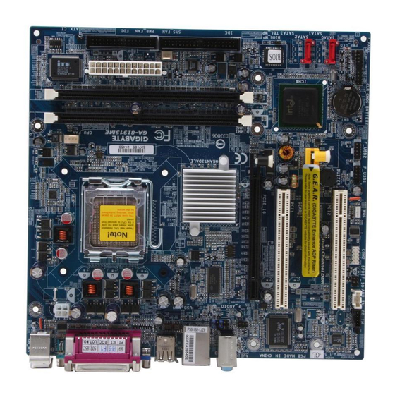
Page 6: Ga-8I915Me Series Motherboard Layout
GA-8I915ME Series Motherboard Layout KB_MS ATX_12V R_USB AUDIO1 PCIE_16 SUR_CEN PCI1 RTL8100C RTL8110S PCI2 CODEC CD_IN AUX_IN Only for GA-8I915ME-GV. Only for GA-8I915ME-GL. Only for GA-8I915ME-C. Only for GA-8I915ME-G. LGA775 Intel 915GV Intel 915GL Intel 910GL Intel 915G GEAR BUZZER... -
Page 7: Block Diagram
Block Diagram PCI-ECLK (100MHz) PCI Express x16 PCI Express x4 PCI Bus RTL8100C RTL8110S 2 PCI RJ45 1 G.E.A.R. PCICLK (33MHz) Only for GA-8I915ME-GV. Only for GA-8I915ME-GL. Only for GA-8I915ME-C. Only for GA-8I915ME-G. CPUCLK+/-(200 LGA775 Processor Host Interface Intel Intel 915GV Intel 915GL Intel 910GL GMCHCLK (200/133MHz) - Page 8 - 8 -...
-
Page 9: Chapter 1 Hardware Installation
2. Damage as a result of violating the conditions recommended in the user manual. 3. Damage due to improper installation. 4. Damage due to use of uncertified components. 5. Damage due to use exceeding the permitted parameters. 6. Product determined to be an unofficial Gigabyte product. - 9 - Hardware Installation... -
Page 10: Feature Summary
Feature Summary Motherboard GA-8I915ME Series motherboard -GA-8I915ME-GV / GA-8I915ME-GL / GA-8I915ME-C / GA-8I915ME-G Supports the latest Intel Supports 800 L2 cache varies with CPU Chipset Northbridge: Intel Southbridge: Intel Supported on the Win 2000/XP operating systems Memory 2 DDR DIMM memory slots (supports up to 4GB memory) Supports dual channel DDR400/333 DIMM Supports 2.5V DDR DIMM... - Page 11 Hardware Monitor System voltage detection CPU temperature detection CPU / System fan speed detection CPU warning temperature CPU / System fan failure warning CPU smart fan control BIOS Use of licensed AWARD BIOS Supports Q-Flash Additional Features Supports @BIOS Supports EasyTune 5 (only supports Hardware Monitor function) Overclocking Over Clock via BIOS (DDR) Form Factor...
-
Page 12: Installation Of The Cpu And Heatsink
Avoid twisting or bending motions that might cause damage to the CPU during installation.) GA-8I915ME Series Motherboard Fig. 2 Remove the plastic covering on the CPU socket. -
Page 13: Installation Of The Heatsink
1-3-2 Installation of the Heatsink Fig.1 Please apply an even layer of heatsink paste on the surface of the installed CPU. Fig. 3 Place the heatsink atop the CPU and make sure the push pins aim to the pin hole on the motherboard.Pressing down the push pins diagonally. -
Page 14: Installation Of Memory
DIMM slot. Then push it down. 3. Close the plastic clip at both edges of the DIMM slots to lock the DIMM module. Reverse the installation steps when you wish to remove the DIMM module. GA-8I915ME Series Motherboard Notch - 14 -... - Page 15 Dual Channel DDR GA-8I915ME-GV/GA-8I915ME-GL/GA-8I915ME-C/GA-8I915ME-G supports the Dual Channel Technology. After operating the Dual Channel Technology, the bandwidth of Memory Bus will add double. GA-8I915ME-GV/GA-8I915ME-GL/GA-8I915ME-C/GA-8I915ME-G includes 2 DIMM sockets, and each Channel has two DIMM sockets as following: Channel A : DIMM1 Channel B : DIMM2 If you want to operate the Dual Channel Technology, please note the following explanations due to the limitation of Intel chipset specifications.
-
Page 16: Installation Of Expansion Cards
Power on the computer, if necessary, setup BIOS utility of expansion card from BIOS. 8. Install related driver from the operating system. Installing a PCI Express x 16/G.E.A.R. expansion card: GA-8I915ME Series Motherboard Please carefully pull out the small white- drawable bar at the end of the PCI Express x 16/G.E.A.R. -
Page 17: What Is G.e.a.r
3. G.E.A.R. interface is created through PCI interface signal and voltage switching to AGP interface, due to this technical specification difference, it might cause AGP graphics card life-span shortens. 4. Please view the graphics cards support list currently validated by GIGABYTE enginneers. For more updated information, please logon to GIGABYTE website at http://www.gigabyte.com.tw 1-5-2 Graphics Card Support List (The items below are all supported under the Windows XP operating system. - Page 18 Graphics Chip Maker Nvidia Gigabyte Gigabyte Gigabyte Gigabyte Gigabyte Gigabyte Gigabyte Gigabyte Gigabyte Gigabyte Gigabyte A S U S GA-8I915ME Series Motherboard Model Name GV-AR64DL-T-SI GV-AR64S-H GV-AP64D GV-AP64DH GV-AP128DG-H GV-AF128D-GH SiS315 64MB V3500 Model Name GV-N57L128D G V-N59X128D V9180TD V9480-TVD...
- Page 19 Figure 3. PCI Express x16 Card Graphics Chip Maker Gigabyte Gigabyte Gigabyte Gigabyte Gigabyte Gigabyte Gigabyte Gigabyte A S U S A S U S Model Name GV-RX30S128D GV-RX60P128D GV-RX60X128V GV-RX70128D GV-RX70P128D GV-RX80T256V G V-RX80L256V G V-RX80256D AX800XT AX700PRO RX600 XT-TD128...
-
Page 20: I/O Back Panel Introduction
Connect the stereo speakers, earphone or front surround speakers to this connector. MIC In Microphone can be connected to MIC In jack. You can use audio software to configure 2-/4-/6- channel audio functioning. Only for GA-8I915ME-GV. Only for GA-8I915ME-GL. Only for GA-8I915ME-C. Only for GA-8I915ME-G. GA-8I915ME Series Motherboard - 20 -... -
Page 21: Connectors Introduction
Connectors Introduction ATX_12V ATX (Power Connector) CPU_FAN SYS_FAN SATA0 / SATA2 F_PANEL PWR_LED F_AUDIO CD_IN AUX_IN F_USB1 / F_USB2 COM2 SUR_CEN SPIDF_IO CLR_CMOS BIOS_WP - 21 - Hardware Installation... - Page 22 If you use a 24-pin ATX power supply, please remove the small cover on the power connector on the motherboard before plugging in the power cord ; Otherwise, please do not remove it. GA-8I915ME Series Motherboard Pin No. Pin No.
- Page 23 3/4) CPU_FAN / SYS_FAN (Cooler Fan Power Connector) The cooler fan power connector supplies a +12V power voltage via a 3-pin/4-pin (only for CPU_FAN) power connector and possesses a foolproof connection design. Most coolers are designed with color-coded power connector wires. A red power connector wire indicates a positive connection and requires a +12V power voltage.
- Page 24 7) SATA0/SATA2 (Serial ATA Connector, Controlled by ICH6) Serial ATA can provide up to 150MB/s transfer rate. Please refer to the BIOS setting for the Serial ATA and install the proper driver in order to work properly. GA-8I915ME Series Motherboard Pin No. Definition...
-
Page 25: Front Panel Jumper
8) F_PANEL (Front Panel Jumper) Please connect the power LED, PC speaker, reset switch and power switch etc of your chassis front panel to the F_PANEL connector according to the pin assignment below. HD (IDE Hard Disk Active LED) SPEAK (Speaker Connector) RES (Reset Switch) PW (Power Switch) MSG(Message LED/Power/Sleep LED) - Page 26 F_AUDIO connector on the motherboard. To find out if the chassis you are buying support front audio panel connector, please contact your dealer. If you want to use "Front Audio" connector, you must remove the jumpers on pin 5-6, 9-10. GA-8I915ME Series Motherboard Pin No. Definition...
- Page 27 12) CD_IN (CD IN) Connect CD-ROM or DVD-ROM audio out to the connector. 13) AUX_IN (AUX In Connector) Connect other device (such as PCI TV Tuner audio out) to the connector. Pin No. Pin No. Definition AUX-L AUX-R - 27 - Hardware Installation Definition CD-L...
- Page 28 Be careful with the polarity of the COM connector. Check the pin assignment carefully while you connect the COM cable, incorrect connection between the cable and connector will make the device unable to work or even damage it. For optional COM cable, please contact your local dealer. GA-8I915ME Series Motherboard Pin No. Definition Power...
- Page 29 16) SUR_CEN Please contact your nearest dealer for optional SUR_CEN cable. 17) SPDIF_IO (SPDIF In/ Out) The SPDIF output is capable of providing digital audio to external speakers or compressed AC3 data to an external Dolby Digital Decoder. Use this feature only when your stereo system has digital input function.
- Page 30 19) CLR_CMOS (Clear CMOS) You may clear the CMOS data to its default values by this jumper. To clear CMOS, temporarily short 1-2 pin. Default doesn't include the "Shunter" to prevent from improper use this jumper. GA-8I915ME Series Motherboard Pin No. Definition...
- Page 31 20) BIOS_WP (BIOS Write Protect) 21) BAT(Battery) Danger of explosion if battery is incorrectly replaced. Replace only with the same or equivalent type recommended by the manufacturer. Dispose of used batteries according to the manufacturer's instructions. Open: Normal Short :Write Protect If you want to erase CMOS...
- Page 32 GA-8I915ME Series Motherboard - 32 -...
-
Page 33: Chapter 2 Bios Setup
BIOS needs to be reset to its original settings. If you wish to upgrade to a new BIOS, either Gigabyte's Q-Flash or @BIOS utility can be used. Q-Flash allows the user to quickly and easily update or backup BIOS without entering the operating system. -
Page 34: The Main Menu
This setup page is control CPU clock and frequency ratio. Load Fail-Safe Defaults Fail-Safe Defaults indicates the value of the system parameters which the system would be in safe configuration. GA-8I915ME Series Motherboard Load Fail-Safe Defaults Load Optimized Defaults Set Supervisor Password Set User Password Save &... - Page 35 Load Optimized Defaults Optimized Defaults indicates the value of the system parameters which the system would be in best performance configuration. Set Supervisor Password Change, set, or disable password. It allows you to limit access to the system and Setup, or just to Setup. Set User Password Change, set, or disable password.
-
Page 36: Standard Cmos Features
Number of heads Precomp Write precomp Landing Zone Landing zone Sector Number of sectors If a hard disk has not been installed, select NONE and press <Enter>. GA-8I915ME Series Motherboard Standard CMOS Features Mon, Mar 28 2005 22:31:24 [None] [None] [None] [None] [1.44M, 3.5"]... - Page 37 Drive A / Drive B The category identifies the types of floppy disk drive A or drive B that has been installed in the computer. None No floppy drive installed 360K, 5.25" 5.25 inch PC-type standard drive; 360K byte capacity. 1.2M, 5.25"...
-
Page 38: Advanced Bios Features
The system will not boot and will not access to Setup page if the correct password is not entered at the prompt. (Note3) This item will show up when you install a processor which supports this function. GA-8I915ME Series Motherboard Advanced BIOS Features [Press Enter]... - Page 39 CPU Hyper-Threading Enabled Enables CPU Hyper Threading Feature. Please note that this feature is only working for operating system with multi processors mode supported. (Default value) Disabled Disables CPU Hyper Threading. Limit CPUID Max. to 3 Enabled Limit CPUID Maximum value to 3 when use older OS like NT4. Disabled Disables CPUID Limit for windows XP.(Default value) Init Display First...
-
Page 40: Integrated Peripherals
Disable USB Controller. USB 2.0 Controller Disable this function if you are not using onboard USB 2.0 feature. Enabled Enable USB 2.0 Controller. (Default value) Disabled Disable USB 2.0 Controller. GA-8I915ME Series Motherboard Integrated Peripherals [Enabled] [Enhanced] Ch.0 Master/Slave Ch.2 Master/Slave [Enabled]... - Page 41 USB Keyboard Support Enabled Enable USB Keyboard Support. Disabled Disable USB Keyboard Support. (Default value) USB Mouse Support Enabled Enable USB Mouse Support. Disabled Disable USB Mouse Support. (Default value) AC97 Audio Auto Auto detect AC97 audio function. (Default value) Disabled Disable AC97 audio function.
-
Page 42: Power Management Setup
Time (hh: mm: ss) Alarm : (0~23) : (0~59) : (0~59) Power On By Mouse Disabled Disable this function. (Default value) Double Click Double click on PS/2 mouse left button to power on the system. GA-8I915ME Series Motherboard Power Management Setup [S1(POS)] [Instant-off] [Enabled] [Enabled]... - Page 43 Power On By Keyboard Password Enter from 1 to 5 characters to set the Keyboard Power On Password. Disabled Disabled this function. (Default value) Keyboard 98 If your keyboard have "POWER Key" button, you can press the key to power on the system. KB Power ON Password When "Power On by Keyboard"...
-
Page 44: Pnp/Pci Configurations
CPU Warning Temperature CPU FAN Fail Warning SYSTEM FAN Fail Warning CPU Smart FAN Control CPU Smart FAN Mode : Move Enter: Select F5: Previous Values GA-8I915ME Series Motherboard PnP/PCI Configurations [Auto] [Auto] [Auto] +/-/PU/PD: Value F10: Save ESC: Exit... - Page 45 Reset Case Open Status Disabled Don't reset case open status. (Default value) Enabled Clear case open status at next boot. Case Opened If the case is closed, "Case Opened" will show "No". If the case have been opened, "Case Opened" will show "Yes". If you want to reset "Case Opened"...
-
Page 46: Frequency/Voltage Control
Set Memory frequency by DRAM SPD data. (Default value) Memory Frequency (Mhz) The values depend on "System Memory Multiplier" item. (Note) This item will show up when you install a processor which supports this function. GA-8I915ME Series Motherboard Frequency/Voltage Control [16X] [Auto] +/-/PU/PD: Value... -
Page 47: Load Fail-Safe Defaults
Load Fail-Safe Defaults CMOS Setup Utility-Copyright (C) 1984-2005 Award Software Standard CMOS Features Advanced BIOS Features Integrated Peripherals Power Management Setup PnP/PCI Configurations PC Health Status Frequency/Voltage Control ESC: Quit F8: Q-Flash Fail-Safe defaults contain the most appropriate values of the system parameters that allow minimum system performance. -
Page 48: Set Supervisor/User Password
Setup Menu. If you select "Setup" at "Password Check" in Advance BIOS Features Menu, you will be prompted only when you try to enter Setup. GA-8I915ME Series Motherboard Load Fail-Safe Defaults Load Optimized Defaults... -
Page 49: Save & Exit Setup
2-11 Save & Exit Setup CMOS Setup Utility-Copyright (C) 1984-2005 Award Software Standard CMOS Features Advanced BIOS Features Integrated Peripherals Power Management Setup PnP/PCI Configurations PC Health Status Frequency/Voltage Control ESC: Quit F8: Q-Flash Type "Y" will quit the Setup Utility and save the user setup value to RTC CMOS. Type "N"... - Page 50 GA-8I915ME Series Motherboard - 50 -...
-
Page 51: Chapter 3 Install Drivers
Chapter 3 Install Drivers Pictures below are shown in Windows XP. Insert the driver CD-title that came with your motherboard into your CD-ROM drive, the driver CD-title will auto start and show the installation guide. If not, please double click the CD-ROM device icon in "My computer", and execute the Run.exe. -
Page 52: Software Applications
Software Applications This page displays all the tools that Gigabyte developed and some free software, you can choose anyone you want and press "install" to install them. Driver CD Information This page lists the contents of software and drivers in this CD-title. -
Page 53: Hardware Information
Hardware Information This page lists all device you have for this motherboard. Contact Us Please see the last page for details. - 53 - Install Drivers... - Page 54 GA-8I915ME Series Motherboard - 54 -...
-
Page 55: Chapter 4 Appendix
Motherboard Intelligent Tweaker (M.I.T.) allows user to access and change BIOS feature settings with relative speed and ease. Through GIGABYTE M.I.T. feature the user is no longer required to switch into different modes within BIOS setup in order to change system settings such as the CPU system bus, memory timings or to enabled Gigabyte's unique C.I.A. -
Page 56: Easytune 5 Introduction
Enters the PC Health setting page Confirmation and Execution button Toggles between Easy and Advance Mode Display panel of CPU frequency Shows the current functions status Log on to GIGABYTE website Display EasyTune 5 Help file Quit or Minimize EasyTune 5 software... -
Page 57: Xpress Recovery2 Introduction
4-1-2 Xpress Recovery2 Introduction Xpress Recovery2 is designed to provide quick backup and restora- tion of hard disk data. Supporting Microsoft operating systems including Windows XP/2000/NT/98/Me and DOS, and file systems including FAT16, FAT32, and NTFS, Xpress Recovery2 is able to back up data on hard disks on PATA and SATA IDE controllers. - Page 58 GA-K8NF-9 (PCB Ver. 1.0) GA-K8NXP-SLI GA-K8NE (PCB Ver. 1.0) GA-K8N Ultra-SLI GA-K8NMF-9 GA-K8N Pro-SLI GA-8I915ME Series Motherboard 1. RESTORE: Restore the backed-up data to your hard disk. (This button will not appear if there is no backup file.) 2. BACKUP: Back up data from hard disk.
-
Page 59: Q-Flash Utility
Updating BIOS with Q-Flash Utility on Dual BIOS Motherboards. Some of Gigabyte motherboards are equipped with dual BIOS. In the BIOS menu of the motherboards supporting Q-Flash and Dual BIOS, the Q-Flash utility and Dual BIOS utility are combined in the same screen. -
Page 60: Flash Bios Method Introduction
Action bar: Contains the names of four actions needed to operate the Q-Flash/Dual BIOS utility. Pressing the buttons mentioned on your keyboards to perform these actions. GA-8I915ME Series Motherboard Select Language Load Fail-Safe Defaults Load Optimized Defaults... - Page 61 Using the Q-Flash utility: This section tells you how to update BIOS using the Q-Flash utility. As described in the "Before you begin" section above, you must prepare a floppy disk having the BIOS file for your motherboard and insert it to your computer.
- Page 62 Primary Slave : None Secondary Master : CREATIVEDVD-RM DVD1242E BC101 Secondary Slave : None Press DEL to enter SETUP / Dual BIOS / Q-Flash / F9 For Xpress Recovery 09/23/2003-i875P-6A79BG03C-00 GA-8I915ME Series Motherboard Dual BIOS Utility Main Bios Disable Boot From Main Bios...
- Page 63 Press Del to enter BIOS menu after system reboots. When you are in BIOS menu, move to Load Fail-Safe Defaults item and press Enter to load BIOS Fail-Safe Defaults. Normally the system redetects all devices after BIOS has been upgraded. Therefore, we highly recommend reloading the BIOS defaults after BIOS has been upgraded.
- Page 64 After BIOS file is read, you'll see a confirmation dialog box asking you "Are you sure to update BIOS?" Please do not take out the floppy disk when it begins flashing BIOS. GA-8I915ME Series Motherboard Q-Flash Utility V1.30 Keep DMI Data...
- Page 65 Press Y button on your keyboard after you are sure to update BIOS. Then it will begin to update BIOS. The progress of updating BIOS will be shown at the same time. Flash Type/Size...SST 49LF003A >>>>>>>>>>>>>>>>>>>... Enter : Run Don't Turn Off Power or Reset System Press any keys to return to the Q-Flash menu when the BIOS updating procedure is completed.
-
Page 66: @Bios Utility
Please select "All Files" in dialog box while opening the old file. Please search for BIOS unzip file, downloading from internet or any other methods (such as: 8I915ME.F2). Complete update process following the instruction. GA-8I915ME Series Motherboard Utility Fig 2. Installation Complete and Run @BIOS Click Sart/ Programs/ GIGABYTE/ @BIOS Fig 4. - Page 67 Otherwise, your system won't boot. III. In method I, if the BIOS file you need cannot be found in @BIOS Gigabyte's web site for downloading and updating it according to method II. IV. Please note that any interruption during updating will cause system unbooted.
-
Page 68: 4- / 6- Channel Audio Function Introduction
Click the icon to select the function. STEP 3: On the AC97 Audio Configuration menu, click the Speaker Configuration tab and select the 2-channel mode for stereo speaker output check box. GA-8I915ME Series Motherboard - 68 -... - Page 69 4 Channel Analog Audio Output Mode STEP 1: Connect the front channels to "Line Out," the rear channels to "Line In." STEP 2: After installing the audio driver, you'll find a Sound Effect icon on the lower right hand taskbar. Click the icon to select the function.
- Page 70 STEP 3: On the AC97 Audio Configuration menu, click the Speaker Configuration tab and select the 6-chan- nel mode for 5.1 speaker output check box. Clear the Only SURROUND-KIT check box and press OK. GA-8I915ME Series Motherboard - 70 -...
- Page 71 Center/Subwoofer channels. It is the best solution if you need 6 channel output, Line In and MIC at the same time. "SURROUND-KIT" is included in the GIGABYTE unique "Audio Combo Kit" as picture. STEP 1: Secure the metal bracket of the"Surround Kit" to the chassis back panel with a screw.
- Page 72 Basic & Advanced 6 Channel Analog Audio Output Mode Notes: When the Environment setting is None, the sound would be performed as stereo mode (2-channel output). Please select the other settings for 6 channels output. GA-8I915ME Series Motherboard - 72 -...
- Page 73 SPDIF Output Device (Optional Device) A "SPDIF output" device is an optional device. The SPDIF_IO cable with rear bracket could link to the "SPDIF_IO" connector (As picture.) For the further linkage to decoder, rear bracket provides coaxial cable and Fiber connecting port. STEP 1: Secure the metal bracket of the SPDIF Output device to the chassis back panel with a screw.
-
Page 74: Jack-Sensing Introduction
Please connect the devices to the right jacks as above. A window will appear as right picture if you setup the devices properly. Please note that 3D audio function will only appear when 3D audio inputs. GA-8I915ME Series Motherboard - 74 -... - Page 75 If you set wrong with the connectors, the warning message will come out as right picture. Manual setting: If the device picture shows different from what you set, please press "Manual Selection" to set. - 75 - Appendix...
-
Page 76: Troubleshooting
Below is a collection of general asked questions. To check general asked questions based on a specific motherboard model, please log on to http://www.gigabyte.com.tw Question 1: I cannot see some options that were included in previous BIOS after updating BIOS. Why? Answer: Some advanced options are hidden in new BIOS version. - Page 77 - 77 - Appendix...
- Page 78 GA-8I915ME Series Motherboard - 78 -...
- Page 79 Address: No.6, Bau Chiang Road, Hsin-Tien, Taipei 231, Taiwan TEL: +886-2-8912-4888 FAX: +886-2-8912-4003 Tech. Support : http://tw.giga-byte.com/TechSupport/ServiceCenter.htm Non-Tech. Support(Sales/Marketing) : http://ggts.gigabyte.com.tw/nontech.asp WEB address (English): http://www.gigabyte.com.tw WEB address (Chinese): http://chinese.giga-byte.com U.S.A. G.B.T. INC. TEL: +1-626-854-9338 FAX: +1-626-854-9339 Tech. Support : http://tw.giga-byte.com/TechSupport/ServiceCenter.htm Non-Tech.
- Page 80 China NINGBO G.B.T. TECH. TRADING CO., LTD. Tech. Support : http://tw.giga-byte.com/TechSupport/ServiceCenter.htm Non-Tech. Support(Sales/Marketing) : http://ggts.gigabyte.com.tw/nontech.asp WEB address : http://www.gigabyte.com.cn Shanghai TEL: +86-021-63410999 FAX: +86-021-63410100 Beijing TEL: +86-10-62102838 FAX: +86-10-62102848 Wuhan TEL: +86-27-87851061 FAX: +86-27-87851330 GuangZhou TEL: +86-20-87586074 FAX: +86-20-85517843 Chengdu...