E-Mu 1212M Owner's Manual
Digital audio systems
Hide thumbs
Also See for 1212M:
- Owner's manual (142 pages) ,
- Quick start manual (108 pages) ,
- Manual (64 pages)
Table of Contents
Advertisement
Advertisement
Table of Contents

Related Manuals for E-Mu 1212M


Summary of Contents for E-Mu 1212M
- Page 1 1820 1820 O w n e r ’ s M a n u a l O w n e r ’ s M a n u a l...
- Page 2 IRELAND E-MU Japan Asia Pacific, Africa, Middle East Creative Media K K Creative Technology Ltd. Kanda Eight Bldg, 3F 31 International Business Park 4-6-7 Soto-Kanda Creative Resource, Singapore 609921 Chiyoda-ku, Tokyo 101-0021 SINGAPORE JAPAN E-MU 1820M/1820/1212M PCI Digital Audio System...
-
Page 3: Table Of Contents
Notes for Installation ....................11 Safety First! ......................... 12 Connector Types ......................12 Installing the E-MU 1010 PCI Card .................. 13 Install the Sync Daughter Card or 0202 Daughter Card..........14 E-MU 0202 & AudioDock ..................15 Rubber Feet ......................... 16 Rack Mounting the AudioDock .................. - Page 4 Overview of the Mixer......................27 Mixer Window ........................ 28 Mixer Block Diagram ..................... 28 Pre Fader or Post Fader ....................28 E-MU Icon in the Windows Taskbar ................. 29 The Toolbar ........................29 The Session ......................... 30 New Session ........................30 Open Session ........................
- Page 5 Effect ........................... 50 Input ........................... 51 Output ........................51 Auxiliary Effects & Returns .................... 52 Sidechain Diagram ..................... 52 Sync/Sample Rate Indicators ..................52 Output Section ....................... 53 Main Inserts ........................ 53 Main Output Fader ..................... 53 Output Level Meters ....................53 Monitor Output Level ....................
- Page 6 E-MU 1820 System at 88.2k/96k (1010 PCI Card & AudioDock) ......111 E-MU 1212M System at 88.2k or 96k (1010 PCI Card & I/O Card) ......112 E-MU 1820 System at 176.4kHz or 192kHz (1010 PCI Card & AudioDock) ..113 E-MU 1212 System at 176.4k/192k (1010 PCI Card &...
- Page 7 7 - Appendix ..............117 Sync Daughter Card Supplement ..................117 SMPTE Conversion ...................... 117 SMPTE Features ......................117 SMPTE Options ......................117 SMPTE Modes of Operation ..................118 Host Mode ........................ 118 External Mode ......................118 Flywheel Mode ......................118 Flywheel Modes ......................
- Page 8 E-MU 1820M/1820/1212M PCI Digital Audio System...
-
Page 9: 1- Introduction
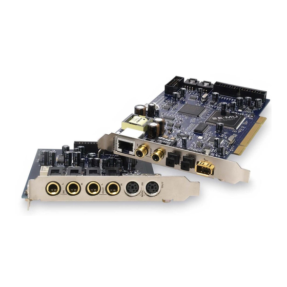
(1) SMPTE (LTC) In & Out All Systems Include: The E-MU 1010 PCI Card is the heart of all three systems. Its powerful hardware DSP processor allows you to use over 16 simultaneous hardware-based effects, which place minimal load on your computer’s CPU. The Firewire port provides high-speed connec- tivity to the Creative NOMAD®... -
Page 10: E-Mu 1212M System
The Sync Daughter Card comes standard with the 1820M system and can be purchased as an optional upgrade to the 1820 and 1212M systems. The Sync Card adds Word Clock in and out for sample-synchronizing outboard digital equipment and SMPTE longitudinal time code in/out for syncing other recording equipment. -
Page 11: Installation
• Multiple Digital Audio System sound cards are not supported. Please read the following sections as they apply to your system as you install the E-MU 1010, paying special attention to the various warnings they include. Prior to installing the hardware, take a few moments to write down the 18-digit serial number, which is located on the back of the box and on the 1010 PCI Card. -
Page 12: Safety First
Firewire Connector Interfaces to Firewire peripherals Warning: The E-MU 1010 PCI Card has been designed to use readily available and inexpensive standard computer system cables to make it easy for you to find replacement cables if your original cables become damaged or lost. However, because these standard cables types are used for other purposes, you must use caution to avoid connecting the cables incorrectly. -
Page 13: Installing The E-Mu 1010 Pci Card
Align the E-MU 1010 PCI card with the slot and press gently but firmly down into the slot as shown in figure 2. Do not force the E-MU 1010 card into the slot. Make sure that the gold finger connector of the card is aligned with the PCI bus connector on the motherboard before you insert the card into the PCI slot. -
Page 14: Install The Sync Daughter Card Or 0202 Daughter Card
firmly down into the slot as shown in figure 2 on the preceding page. Do not force the E-MU Card into the slot. Make sure that the tab at the rear of the card is aligned with the PCI bus connector on the motherboard before you insert the card into the PCI slot. -
Page 15: E-Mu 0202 & Audiodock
Install the Sync Daughter Card or 0202 Daughter Card E-MU 0202 & AudioDock If you have both the E-MU 0202 I/O card and the AudioDock, you are advised not to connect both to the same E-MU 1010 PCI card using this version of software. There are known issues with doing this what will be addressed in a future software update. -
Page 16: Rubber Feet
2 - Installation Install the Sync Daughter Card or 0202 Daughter Card Rubber Feet Four rubber feet were included with the AudioDock. These feet should be used if you’re not going to rack mount the AudioDock. If you are going to rack mount the AudioDock, leave the feet off. -
Page 17: Software Installation
Software Installation Installing the E-MU 1010 Drivers The first time you restart your PC after installing the E-MU 1010 PCI card, you will need to install the PatchMix DSP software and E-MU 1010 PCI card drivers. Windows XP , Windows XP x64, Windows Vista, Windows Vista x64 The software is not compatible with other versions of Windows. -
Page 18: Note About Windows Logo Testing
2 - Installation Software Installation Note About Windows Logo Testing When you install the Digital Audio System drivers, you will see a dialog box informing you either that the driver has not been certified by Windows Hardware Quality Labs (WHQL), or that the driver is signed by Creative Labs, Inc, and you will be asked if you would like to continue with the installation. -
Page 19: Pci Card & Interfaces
3 - PCI Card & Interfaces The E-MU 1010 PCI Card The E-MU 1010 PCI card is the heart of the system and contains E-MU’s powerful E-DSP chip. The powerful hardware DSP on this card leaves more power free on your CPU for additional software plug-ins and other tasks. -
Page 20: Ieee1394 Firewire
The 0202 Daughter Card The 0202 Daughter card is the companion card for E-MU 1010 systems which don’t include the AudioDock. The 0202 Daughter card provides one pair of 24-bit balanced analog inputs and one pair of 24-bit balanced analog outputs, plus MIDI in and out. -
Page 21: The Audiodock
3 - PCI Card & Interfaces The AudioDock The AudioDock The AudioDock connects to the E-MU 1010 PCI card via the EDI cable. The AudioDock provides (6) balanced analog inputs, a pair of microphone preamp The AudioDock is inputs, (8) balanced line-level analog outputs, (4) 1/8” outputs for connecting powered completely “hot... -
Page 22: Front Panel Connections
3 - PCI Card & Interfaces The AudioDock Front Panel Connections Insert 1/4" Signal/Clip Phantom S/PDIF Plug for Line Level Indicators Power On/Off Optical Out Indicators -10dB to +25dB Gain Insert XLR Plug Input Gain MIDI #1 Headphone Headphone for Mic Level Controls I/O Jacks Output... -
Page 23: The Audiodock Front Panel Indicators
(i.e. abrupt sample rate change or unplugging of physical master source). the E-MU 1010 is tolerant to minor drifting within the supported rates of 44.1k, 48k, 88k, 96k, 176k and 192k, but if the sample rate drifts out of range (1%) the “Lock” LED will be extinguished. -
Page 24: Rear Panel Connections
(configured as 3 stereo pairs) Outputs In/Out E-MU 1010 Card Line Level Analog Inputs Six balanced 24-bit, line-level, analog inputs are provided (1-3). These can be used to input any line level signal from keyboards, CD-players, cassette decks, etc. The analog inputs are assigned to mixer strips in the mixer application. -
Page 25: Computer Speaker Analog Outputs
A second, independent set of MIDI input and output ports which can be assigned in your specific MIDI application. EDI Connector (Card) Connects to the AudioDock to the E-MU 1010 PCI card using a CAT5 computer cable. The cable supplied with the AudioDock is specially shielded to prevent unwanted RF emissions. -
Page 26: The Sync Daughter Card
The Sync Daughter Card The Sync Daughter Card The Sync Daughter card (included in the E-MU 1820M system and available as an option for other systems) provides word clock in and out, SMPTE (LTC) in and out and an additional MIDI output for transmitting MIDI Time Code (MTC). MIDI Time Code is a special rendering of SMPTE that can be transmitted over MIDI cables. -
Page 27: The Patchmix Dsp Mixer
Rate Indicators Solo/Mute Buttons Monitor User Volume/Balance Definable /Mute Controls Main Current Main Mix Scribble Strip WAVE Strip Inserts Session Output Volume Controls Windows Source Audio Name & Meters (Direct Sound, Windows Media, etc.) E-MU 1820M/1820/1212M PCI Digital Audio System... -
Page 28: Mixer Window
4 - The PatchMix DSP Mixer Overview of the Mixer Mixer Window The Mixer consists of four main sections. Application Toolbar Lets you manage sessions and show/hide the various views. Main Section Controls all the main levels, aux buses, and their inserts. This section also has a “TV”... -
Page 29: E-Mu Icon In The Windows Taskbar
Calls up the Global Preferences window. Sync Settings Calls up the SMPTE window. (if Sync Card is installed) About PatchMix DSP Right-Click on the E-MU logo to view the “About PatchMix DSP” screen, which provides the software and firmware version numbers and other information. -
Page 30: The Session
4 - The PatchMix DSP Mixer The Session The Session The current state of the PatchMix DSP mixer (fader settings, effects routings…every- thing!) can be saved as a Session. Whenever you create or modify a mixer setup, all you have to do is Save it to be able to recall it at a later time. Before you begin using PatchMix DSP, you need to set it up to be compatible with the other software applications you may be running. -
Page 31: Open Session
88.2kHz/96kHz, and 176.4kHz/192kHz. You can create your own templates by simply copying or saving sessions into the “Session Templates” folder (Program Files\Creative Professional\E-MU PatchMix DSP\Session Templates). The system model number in parenthesis (1820) or (1212) must precede the template name in order to be recognized as a template. -
Page 32: Using External Clock
4 - The PatchMix DSP Mixer The Session The System Settings include the following: Note: if set to “External” without an • Internal/External Clock Selects between internal or external word clock source external clock present, as the master clock source for the system PatchMix DSP defaults to •... -
Page 33: I/O Settings
Input too weak? Use -10 Input setting. Output too weak? Use +4 Output setting Input Level Output Level Settings Settings E-MU 1010 E-MU 1010 Optical Input Optical Select Output Select S/PDIF Output Format Select E-MU Digital Audio System... - Page 34 4 - The PatchMix DSP Mixer The Session • Inputs +4 or -10 Selects between Consumer level (-10dBV) or Professional level (+4dBu) inputs. (Use the -10dBV setting if your input is too weak.) • Outputs +4 or -10 Selects between Consumer level (-10dBV) or Professional level (+4dBu) outputs.
-
Page 35: Input Mixer Strips
This screen shows a mono strip on the left and a Scribble Strips stereo strip on the right. Click inside the scribble strip and type a name of up to eight characters. E-MU Digital Audio System... -
Page 36: Mixer Strip Creation
24-bit mono or stereo analog input from the AudioDock. Physical: PCI Card S/PDIF 2 channel digital audio from the S/PDIF input on the E-MU 1010 card. Physical: PCI Card ADAT 2 channel digital audio from the ADAT input on the E-MU 1010 card... -
Page 37: Multichannel Wave Files
Rear Left / Rear Right 2L = RL 2R = RR 2 (Tip = RL Ring = RR) E-DSP WAVE 7/8 Side Left / Side Right 4L =SL 4R = SR 4 (Tip = SL Ring = SR) E-MU Digital Audio System... -
Page 38: Insert Section
4 - The PatchMix DSP Mixer Mixer Strip Creation Insert Section The Insert Section is next in line. PatchMix DSP effects can be selected from the Effects Palette and dropped into the insert locations. See “The Effects Palette”. Any number of effects can be inserted in series. -
Page 39: The Insert Menu
Right-Click over the Insert section. A pop-up dialog box appears. Select “Insert Send/Return (Physical Output and Input)” from the list of options. The following dialog box appears. E-MU Digital Audio System... -
Page 40: Using External Sends & Returns
4 - The PatchMix DSP Mixer Mixer Strip Creation If the source or Input destination you want to use is not available in the To Physical Output Insert list, they are probably Send/Return From Physical Input already being used elsewhere. Check the Panning input Strips, Inserts and Output Assignments. -
Page 41: Asio Direct Monitor Send/Return
Choose one of the Send Outputs. Click on a destination to select it. Choose one of the Return Inputs. Click on a source to select it. Click OK to select the Send and Return, or Cancel to cancel the operation. E-MU Digital Audio System... -
Page 42: Meter Inserts
4 - The PatchMix DSP Mixer Mixer Strip Creation Meter Inserts Keeping track of signal levels is important in any audio system, be it analog or digital. You want to keep the signal levels running as close to maximum in order to achieve high resolution and low noise. -
Page 43: Making The Best Possible Recording
first place. Trim Pots can be used in emergency situations if there's no other way to get a hot signal in, but they were designed to adjust levels feeding effect plug-ins. E-MU Digital Audio System... -
Page 44: Trim Pot Insert
4 - The PatchMix DSP Mixer Mixer Strip Creation Trim Pot Insert The Trim Pot Insert allows you to adjust the level of a signal in an insert location. The trim pot provides up to ±30dB of gain or attenuation and a phase inverter. The trim pot also has a built-in stereo peak meter after the control. -
Page 45: Managing Your Inserts
Click on the Effect (in the Insert section) and select Effect in the TV display. Click the Solo button. Method #2 Right-Click over the Effect you want to Solo (in the Insert section). A pop-up dialog box appears. Select Solo Insert from the list of options. E-MU Digital Audio System... -
Page 46: Aux Section
4 - The PatchMix DSP Mixer Mixer Strip Creation Aux Section The Auxiliary Sends tap the signal from the channel strips and sum them together before sending the mix to the Auxiliary Effects section. In a traditional mixing console, aux sends are used to send part of the signal to outboard effect devices, then return the effected signal back into the mix using the effect returns. -
Page 47: Pre Or Post Fader Aux Sends
Post-Fader Aux Send Volume Fader & Mute affects both Aux Send Levels Fader Mute Send Return Amount Amount Side Chain Aux Bus 1 Send Return Amount Amount Side Chain Aux Bus 2 Main / Monitor Bus Output E-MU Digital Audio System... -
Page 48: Level, Pan, Solo & Mute Controls
4 - The PatchMix DSP Mixer Mixer Strip Creation Level, Pan, Solo & Mute Controls The Pan control comes before the Level Control and Aux Sends in the signal flow. On stereo strips Pan Controls we use an unconventional pan section with two pan pots –... -
Page 49: Main Section
There is a stereo peak meter that indicates the signal strength for the main mix. The Monitor section has a volume, balance, and a mute control to cut off the monitor output. E-MU Digital Audio System... -
Page 50: Tv Screen & Selectors
4 - The PatchMix DSP Mixer Main Section TV Screen & Selectors The “TV screen” at the top of the main section is a multi-function display and control center for the input and output routings and effect controls. The three buttons at the top of the display select the current function of the display—Effect, Inputs or Outputs. -
Page 51: Input
(or break) a connection. The Host Output screen displays and allows you to view the Host (ASIO or WAVE) outputs of the mixer. See “Insert Section” for information on how to connect the inserts. E-MU Digital Audio System... -
Page 52: Auxiliary Effects & Returns
4 - The PatchMix DSP Mixer Main Section Auxiliary Effects & Returns The section immediately below the TV Screen is where you assign the Auxiliary Effects. The Wet/Dry mix In a traditional mixing console, auxiliary effects sends are used to send part of the signal setting in the effect should normally be set to to outboard effect devices, then return the effected signal back into the mix using the... -
Page 53: Output Section
This button completely cuts off the monitor output and provides a convenient way to instantly kill all sound without having to re-adjust the monitor level later. When the telephone rings, just hit the monitor mute to cut the noise. E-MU Digital Audio System... - Page 54 4 - The PatchMix DSP Mixer Main Section Creative Professional...
-
Page 55: Effects
Chains, see “FX Insert Chains” on page 56. New Folder Icon Import/Export FX Effect Categories Core Effects Multi-Effects Distortion Lo-fi Drums & Percussion Environment Equalization Guitar Morpher Multi Effects Reverb Synths & Keys Vocal E-MU 1820M/1820/1212M PCI Digital Audio System... -
Page 56: Fx Insert Chains
5 - Effects The Effects Palette To Select an Effect Click the FX button to bring up the Effects Palette. The effect palette contains numerous folders containing effects presets. Click on any folder to open it. Select the effect you wish to use by clicking on it with the left mouse button and The order of effects in while continuing to hold the mouse button, drag the effect into the desired location a chain can have a big... -
Page 57: The Order Of Effects
Right-click on the category folder you wish to rename. A pop-up selection box appears. Select “Rename Category”. A pop-up dialog box appears, asking you to “Enter New Category Name.” Click OK to rename the folder or Cancel to cancel the operation. E-MU Digital Audio System... -
Page 58: Importing And Exporting Core Fx Presets And Fx Insert Chains
You can share presets with your friends or download new presets from the Internet. To Import Core FX Presets This option imports complete folders of Core FX presets into the E-MU PatchMix DSP folder (normally located here: “C:\Program Files\Creative Professional\E-MU PatchMix DSP\Core Effects”). -
Page 59: Fx Edit Screen
Inserts can also be soloed. Solo bypasses all the other inserts in the strip and allows you to hear only the soloed effect. This feature is very useful when adjusting the effect parameters. Method #1 Click on the Insert Effect (in the Insert section). Click the Solo button in the TV display. E-MU Digital Audio System... -
Page 60: User Preset Section
5 - Effects FX Edit Screen Method #2 Right-click over the Insert Effect you want to Solo (in the Insert section). A pop-up menu appears. Select “Solo Insert” from the list of options. The other Insert Effect names in the strip will “gray-out”... -
Page 61: Core Effects And Effects Presets
Core Effects and Effects Presets The Core Effects cannot be removed or copied. Effect presets (stored in “C:\Program Files\Creative Professional\Digital Audio System\E-MU PatchMix DSP\Effect Presets”) can be copied, e-mailed or shared like any other computer file. Hint: You can open the effects presets with “NotePad” or other word processor to view and edit the name and parameters. -
Page 62: List Of Core Effects
5 - Effects List of Core Effects List of Core Effects Stereo Reverb Rotary Mono Delay 250 Lite Reverb Phase Shifter Mono Delay 500 RFX Compressor Frequency Shifter Mono Delay 750 Compressor Auto-Wah Mono Delay 1500 Reshaper Vocal Morpher Mono Delay 3000 gate 1-Band Para EQ Stereo Delay 100... -
Page 63: Core Effects Descriptions
Sets the amount of cut (-) or boost (+) of the shelf. Range: -15dB to +15dB Corner Frequency Sets the frequency where the signal begins getting cut or boosted with the Gain control. Range: 80Hz to 16kHz E-MU Digital Audio System... -
Page 64: 3-Band Eq
5 - Effects Core Effects Descriptions 3-Band EQ This versatile equalizer provides two shelving filters at the high and low ends of the frequency range and a fully parametric band in the center. Up to ±24 dB of boost or cut is provided for each band. -
Page 65: 4-Band Eq
Sets the amount of cut (-) or boost (+) of the low frequency shelf. Range: -24dB to +24dB Low Corner Freq. Sets the frequency where the signal begins getting cut or boosted with the Low Gain control. Range: 50Hz to 800Hz E-MU Digital Audio System... -
Page 66: Auto-Wah
5 - Effects Core Effects Descriptions Auto-Wah This effect creates the sound of a guitar wah-wah pedal. The “Wah” filter sweep is automatically triggered from the amplitude envelope of the input sound. Auto-wah works well with percussive sounds such as guitar or bass. The Auto-Wah is a bandpass filter whose frequency can be swept up or down by an envelope follower, which extracts the volume contour of the input signal. -
Page 67: Chorus
This level is called the Threshold, which just happens to be the most important control on the compressor. Delay Level Control Threshold Post Gain Ratio Attack Release E-MU Digital Audio System... -
Page 68: Basic Controls
5 - Effects Core Effects Descriptions Basic Controls The three main controls of a compressor are the Ratio control, the Threshold control and the Gain control. If the signal falls below the Threshold, no processing will take place. Signals exceeding the Threshold will have gain reduction applied as set by the ratio control. -
Page 69: Distortion
Sets the output volume of the effect. Range: -60dB to 0dB Post EQ Center Freq. Sets the frequency of the output bandpass filter. Range: 80Hz to 24kHz Post EQ Bandwidth Sets the width of the output bandpass filter. Range: 80Hz to 24kHz E-MU Digital Audio System... -
Page 70: Flanger
5 - Effects Core Effects Descriptions Flanger A flanger is a very short delay line whose output is mixed back together with the original sound. Mixing the original and delayed signals results in multiple frequency cancella- tions known as a comb filter. Since the flanger is a type of filter, it works best with harmonically rich sounds. -
Page 71: Freq Shifter
Sets the number of Hz that will be added or subtracted with every harmonic in the signal. Range: .01Hz to 24kHz Left Direction Sets pitch shift up or down for the left channel. Right Direction Sets pitch shift up or down for the right channel. E-MU Digital Audio System... -
Page 72: Leveling Amp
5 - Effects Core Effects Descriptions Leveling Amp The first compressors developed in the 1950’s were based on a slow-acting optical gain cells which were able to control the signal level in a very subtle and musical way. This effect is a digital recreation of the leveling amps of yesteryear. The leveling amp uses a large amount of “lookahead delay”... -
Page 73: Lite Reverb
Range: 0% to 100% Early Reflections Sets the volume of the initial wall reflections. Range: 0% to 100% Reverberance Sets the amount of scattering of the early reflections and the reverberation cloud. Range: 0% to 100% E-MU Digital Audio System... -
Page 74: Mono Delays - 100, 250, 500, 750, 1500, 3000
5 - Effects Core Effects Descriptions Mono Delays - 100, 250, 500, 750, 1500, 3000 A delay line makes a copy of the incoming audio, holds it in memory, then plays it back after a predetermined time. The delay number refers to the maximum delay time that can be produced by the delay line. -
Page 75: Phase Shifter
The Rotary incorporates acceleration and deceleration as you switch between the two speeds. Parameter Description Speed Switches between slow or fast rotor speeds with acceleration and deceleration as the speed changes. E-MU Digital Audio System... -
Page 76: Speaker Simulator
5 - Effects Core Effects Descriptions Speaker Simulator The Speaker Simulator provides realistic guitar speaker responses and is designed for use with guitar, bass or synthesizer. Twelve popular guitar amp speaker cabinets are modeled. There is only one parameter on this effect. Just select the speaker you want and listen. Normally this effect should be used with the Mix control set to 100%. -
Page 77: Stereo Delays - 100, 250, 500, 750, 1500
Range: 1 millisecond to 1.5 seconds Feedback Sets the amount of delayed signal that will be recirculated through the delay line. Range: 0% to 100% High Freq. Rolloff Damps high frequencies in the feedback path. Range: 0% to 100% E-MU Digital Audio System... - Page 78 5 - Effects Core Effects Descriptions Stereo Reverb Reverberation is a simulation of a natural space such as a room or hall. The stereo reverb algorithm is designed to simulate various halls, rooms and reverberation plates. Decay time defines the time it takes for the reflected sound from the room to decay or die away.
-
Page 79: Vocal Morpher
Adjusts the frequency of Phoneme B up or down 2 octaves in Tuning semitone intervals. Range: -24 semitones to +24 semitones LFO Rate Controls how fast the phonemes morph back and forth. Range: .01Hz to 10Hz LFO Waveform Selects the waveform for the morph: Sinusoid, Triangle, Sawtooth E-MU Digital Audio System... -
Page 80: Gate
5 - Effects Core Effects Descriptions Gate This stereo noise gate is useful both for background noise reduction applications and also for special effects. The gate uses an envelope follower and threshold detector to turn on its output when the input signal is above the turn-on threshold, and shut down its output when the signal falls below the shut-off threshold. -
Page 81: Parameters
Gate turns on. However, this is actually implemented by adding a 1 millisecond delay to the signal through the gate. For appli- cations where this additional 1 millisecond latency is a problem, the Lookahead can be turned Off. E-MU Digital Audio System... -
Page 82: Level Meter
5 - Effects Core Effects Descriptions Level Meter This meter represents the input signal level in dB, and is in fact the output of the Gate's envelope follower. Since the envelope follower is driven by the greater of the left or right channel, this monophonic meter represents the greater of the two input signals. -
Page 83: Reshaper
Release Level where it remains until the another input transient triggers the next Attack phase. 0 dB Threshold Release Threshold Original Waveform 0 dB Sustain Level Release Level Attack Decay Hold Release Time Time Time Time Reshaped Waveform E-MU Digital Audio System... - Page 84 5 - Effects Core Effects Descriptions Attack, Decay and Release times are all adjustable, and the shape of each of these segments is selectable between exponential, linear, or logarithmic. An additional Hold Time can be used to extend the Sustain phase past the point where the signal has passed the Release Threshold.
- Page 85 Release Curve This parameter selects gain curves exactly as for the Attack Curve parameter, except that the selected curves apply to both the Decay and Release phases of the ADSR. E-MU Digital Audio System...
-
Page 86: Multimode Eq
5 - Effects Core Effects Descriptions Multimode EQ The Multimode EQ is a flexible stereo filter that is capable of implementing a range of powerful filter topologies. It is useful both for utility EQ applications and also for special effects. The Multimode EQ is built from an array of filter sections that can be configured to support: •... -
Page 87: Parameters
The frequency response of the highpass filter looks something like the diagram below: In this mode, the Highpass filter can have up to a 48dB/octave rolloff slope. The Highpass Rolloff, Highpass Frequency and Highpass Resonance parameters are available for editing the filter response. E-MU Digital Audio System... -
Page 88: Highpass -> Lowpass
5 - Effects Core Effects Descriptions Highpass -> Lowpass In this mode, the Lowpass and Highpass filters are connected in series and both sets of Lowpass and Highpass parameters are exposed and independently editable to create the overall filter response. The maximum rolloff slope of each filter is limited to 24dB/ octave in this mode. -
Page 89: Band Pass
Lowpass and Highpass filters. In this mode the rolloff slope on the high and low sides of the cut-band is symmetrical and is limited to a maximum of 24dB/octave.The Resonance is also common to both filter sections . Resonance = 0 E-MU Digital Audio System... -
Page 90: Rfx Compressor
5 - Effects Core Effects Descriptions RFX Compressor The RFX Compressor is a full-featured stereo compressor effect which features the standard parameters available on most compressors as well as a collection of additional advanced parameters that are useful for more sophisticated applications and special effects: •... -
Page 91: Parameters
When the Auto-release parameter is in its signal-dependent settings, the Release time shown represents the shortest possible release time. In Auto-release modes the displayed Release time will be automatically extended depending on the dynamics of the input signal. E-MU Digital Audio System... -
Page 92: Gain
5 - Effects Core Effects Descriptions Gain Sets the compressor's output gain in dB, from +60dB boost to-60dB cut. This control Caution! The Gain follows all of the other elements in the compressor's signal path, so positive gain boost control can increase the signal level to the point of can be used to make up for the gain reduction normally applied to signals above the clipping. - Page 93 Gain parameter. Thus signal levels below the Threshold increase as the Soft Knee depth lower signal levels to and/or Ratio is increased (but see the Gate parameter, below.) peak limiting at maximum signal level E-MU Digital Audio System...
-
Page 94: Gate
5 - Effects Core Effects Descriptions Gate This parameter enables automatic gain reduction on signals that fall from 1 to 120dB below the Threshold point (or Soft Knee threshold, if enabled.) This can act effectively as a “noise gate” on low-level signals that have been boosted by the action of the Gain or Soft Knee parameters. -
Page 95: Auto-Release
Ratio settings than at lower ones. Uncompressed Waveform Longer Release Short Release Program-Dependent Release With Auto-release turned on, the release time becomes longer after an extended period of compression. E-MU Digital Audio System... -
Page 96: Max Compression
5 - Effects Core Effects Descriptions Max Compression This parameter is used to limit the amount of gain reduction that the compressor can apply. The limit is set as a maximum number of dB of gain reduction, from 3dB to UNLIMITED. -
Page 97: Input Mode
Attack and Release times — use a liberal amount of Compression Lookahead to keep the background from masking the beginning of foreground sounds. Creating a Ducker Ducker Background Signal Gain Pan -90 (L) Cell Stereo Strip Foreground Signal Sidechain Pan +90 (R) E-MU Digital Audio System... -
Page 98: Example Settings
5 - Effects Core Effects Descriptions Example Settings Here we have provided a few examples to show the varied uses of this useful tool. Bear in mind that these examples are simply starting points and that you will undoubtedly need to fine tune the parameters to fit the program material and to suit your own taste. Increase Drum Punch: Adjust the Threshold control to control the amount of compression. - Page 99 • Threshold: -37dB (adjust according to the sound) • Ratio: -1:1 (Neg. Compression enabled) • Attack: Instantaneous • Release: 200 msec • Gain: +19dB • Soft Knee: Off • Gate: Off • Comp. Lookahead: -24 msec • Auto-release: Off • Max. Compression: Unlimited E-MU Digital Audio System...
-
Page 100: Multimode Eq Settings
5 - Effects Core Effects Descriptions Creating a De-esser: A de-esser reduces the sibilance or “sss” sound in a vocal part. The sidechain feature of the RFX Compressor makes it possible to create a effective de-esser using the compressor and the Multimode EQ. The Wet/Dry Mix on each effect should be set to 100% The idea is to boost the high frequency content going to the sidechain (R input) so that the compressor will turn down the volume in the presence of sibilance. -
Page 101: E-Mu Powerfx
The hardware-accelerated effects of the E-MU Digital Audio System can also be used as E-MU PowerFX are not VST inserts in Cubase LE. E-MU PowerFX allow you to use PatchMix DSP effects from available at 96kHz and 192kHz sample rates. - Page 102 Using any driver other than “E-MU ASIO” may Launch Cubase LE. produce undesirable Instantiate E-MU PowerFX in an Insert or Aux Send location within Cubase (go to results when using E-MU PowerFX. the EMU folder in VST plug-ins). Press the Insert Edit button in Cubase to bring up the E-MU PowerFX plug-in window shown on the previous page.
-
Page 103: Automating E-Mu Powerfx
• If DSP resources ARE available, but no Hardware I/O Paths are available, the plug-in will run in soft pass-through mode. • If the sample rate is changed in the middle of a E-MU PowerFX session, E-MU PowerFX plug-ins will be bypassed, since the hardware effects cannot operate at 96kHz or 192kHz. - Page 104 5 - Effects E-MU PowerFX E-MU PowerFX Compatibility Chart Extra Application Name Compatible? Note Render Buffers Steinberg Cubase VST 5.1 Steinberg Cubase SX 1 Steinberg Cubase SX 2 Instrument Freeze triggers error if not in render mode. Steinberg Cubase LE...
-
Page 105: Rendering Audio With E-Mu Powerfx
Stuttering in the audio can occur when rendering with SoundForge or any version of Steinberg WaveLab. This problem is caused by discontinuities in the first few audio buffers as they are fed by WaveLab to E-MU PowerFX. The problem can be eliminated by following these guidelines. -
Page 106: E-Mu E-Wire Vst
VST chain. In addition, E-Wire also allows you to insert outboard audio gear into the VST environment. E-Wire has three main components: Note: It’ s easier to use E-MU PowerFX instead of • A VST plug-in which handles the audio routing to PatchMix DSP. E-Wire if you just want to use the hardware effects. -
Page 107: E-Delay Compensator
E-Wire on any other audio tracks. That’s it. E-Delay Compensator As audio is transferred back and forth between the VST host application and the E-MU sound hardware, a delay in the audio stream is incurred. Normally this delay is compen- sated for automatically by the host application, but not all VST host applications support this automatic compensation. -
Page 108: E-Delay Compensator Use
5 - Effects E-MU E-Wire VST Currently automatic delay compensation is supported by the Steinberg 2.0 family (Nuendo 2.x, Cubase SX 2.0, Cubase LE 2.0,), Magix Samplitude 7.x, and Sonar (using the Cakewalk VST adapter 4.4.1), but not by Steinberg Cubase VST 5.1 and Cubasis. -
Page 109: Grouping Tracks
E-Delay Compensator on the output of the group or bus. • E-MU Digital Audio System and PatchMix DSP must be installed. • E-Wire is compatible with Cubase SX/SL/LE, Cubase VST, Wavelab, and Cakewalk Sonar (via DirectX-VST adapter) among others. - Page 110 5 - Effects E-MU E-Wire VST Creative Professional...
-
Page 111: Using High Sample Rates
(see above). There are two possible input configurations when using the E-MU 1820 system at 88.2k/96k as shown in the chart below. Basically, you have the option of using the (4) ADAT input channels or (4) Line Inputs (Line Inputs 2 and 3). -
Page 112: E-Mu 1212M System At 88.2K Or 96K (1010 Pci Card & I/O Card)
E-MU 1212M System at 88.2k or 96k (1010 PCI Card & I/O Card) When using the E-MU 1212 system at 88.2kHz or 96kHz you have two analog inputs and outputs and two S/PDIF inputs and outputs. The ADAT input/output channels are reduced from eight to four using the S/MUX standard. -
Page 113: E-Mu 1820 System At 176.4Khz Or 192Khz (1010 Pci Card & Audiodock)
(1010 PCI Card & AudioDock) At the highest sample rate you have 4 inputs and 10 output channels. There are four possible input configurations when using the E-MU 1820 system at 176.4kHz or 192kHz. Each of the three options provides four input channels. - Page 114 6 - Using High Sample Rates Overview Microphone & Line 3 Input enabled ADOCK 2 Chan. or… Microphone & ADAT Input enabled ADOCK 2 Chan. 2 Chan. or… Line Input 1 & ADAT Input enabled ADOCK 2 Chan. 2 Chan. or…...
-
Page 115: Wdm Recording And Playback Behavior
NO AUDIO will be produced or recorded. In other words, the WDM driver does not perform sample rate conversion of any kind when PatchMix is running at 88.2kHz, 96kHz, 176.4kHz or 192kHz. E-MU 1820M/1820/1212M PCI Digital Audio System... - Page 116 6 - Using High Sample Rates Overview Creative Professional...
-
Page 117: Appendix
Flywheel Mode Start Striping Current Time Start Time • Off • Continuous Flywheel • Fixed •1-time Jam Amount SMPTE Frame Stop Output Word Clock Output SMPTE Status/ Source Termination Rate Settings Striping Level Error Indicators E-MU 1820M/1820/1212M PCI Digital Audio System... -
Page 118: Smpte Modes Of Operation
7 - Appendix Sync Daughter Card Supplement Sets the transmitted frame rate when striping SMPTE. Mode (fps) Edit this field to set the start time in hours:minutes:seconds:frames for SMPTE Striping striping SMPTE. Initiates SMPTE Time Code generation at the SMPTE output beginning at Stripe Button the time set in the striping display. -
Page 119: Stripe Mode
The four frame rates are all straightforward except 30 drop-frame. The 30 df rate came about because the US color video frame rate is actually 29.97 frames/sec instead of 30 frames/sec. This adds up to an error of 108 frames each hour relative to “wall clock” E-MU 1820M/1820/1212M PCI Digital Audio System... -
Page 120: Why Use Smpte
7 - Appendix SMPTE Background time! (A one hour program would actually be 59 minutes and 56.4 seconds long.) Drop frame was designed to correct this time difference. In 30 Drop Frame, every minute except 00-10-20-30-40-50 have the first two frames, 00 and 01, “dropped”, hence the name drop-frame. -
Page 121: Duplicating Smpte Time Code
The Sync Card should not be used as both the SMPTE and word clock master. Word Clock is generated by the Digital Audio System and NOT by the software application (Cubase). SMPTE is not locked to Word Clock inside the Sync Card—they are completely independent. E-MU 1820M/1820/1212M PCI Digital Audio System... -
Page 122: Midi Time Code (Mtc)
The E-MU 1010 PCI card can be externally clocked from the ADAT input, S/PDIF input or from the Sync Daughter card (if installed). In a digital studio, all digital devices in the system should run off the same master Word Clock. - Page 123 Word Clock Termination ON This diagram shows the proper way to connect word clock if you don’t have a multi-output word clock generator. The last device in a Word Clock chain should have Termination ON. E-MU 1820M/1820/1212M PCI Digital Audio System...
-
Page 124: Getting In Sync
In the first example, only the A/D converters on the external device are being used. Only one lightpipe is needed as long as PatchMix is set to receive its word clock signal from the external device. The external A/D is the Master and the E-MU DAS is the Slave. External Device supplies Master Clock... -
Page 125: Useful Information
This simple adapter cable allows you to receive AES/EBU digital audio via the S/PDIF input on the E-MU 1010 PCI card. This cable may also work to connect S/PDIF out from the 1010 PCI card to the AES/EBU input of other digital equipment. -
Page 126: Unbalanced Cables
7 - Appendix Useful Information Unbalanced Cables Unbalanced cables have one conductor and one ground (shield) and usually connect via unbalanced 1/4" phone plugs or RCA phono plugs. The shield stays at a constant ground potential while the signal in the center conductor varies in positive and negative voltage. -
Page 127: Technical Specifications
+0.0/-0.35 dB, 20 Hz - 20 kHz Frequency Response -105 dB (.0006%) 1kHz signal at -1dBFS THD + N 120 dB (A-weighted) 120 dB (A-weighted) Dynamic Range < -120 dB, 1kHz Stereo Crosstalk 560 ohms Output Impedance E-MU 1820M/1820/1212M PCI Digital Audio System... - Page 128 7 - Appendix Technical Specifications Specifications: 1820M System MIC PREAMP/LINE INPUT TFPro™ combination microphone preamp and line input Type +0.8/-0.1 dB, 20 Hz - 20kHz Frequency Response < 120 dB, 1kHz Stereo Crosstalk LINE INPUT -12 to +28 dB Gain Range: -17 dbV (19.2 dBu) Max Level: -100 dB (.001%), 1 kHz at -1 dBFS...
- Page 129 24, 25, 30 drop, 30 non-drop frames/second. Frame Rates Compatible with 29.97 fps timecode Regeneration, stripe and conversion modes Modes 0.5 - 4V p-p Input Level: +4 dBu, -10 dBV (software selectable) Output Level: 10K ohm Input Impedance: E-MU 1820M/1820/1212M PCI Digital Audio System...
- Page 130 7 - Appendix Technical Specifications Specifications: 1820 System GENERAL 44.1 kHz. 48 kHz, 88.2 kHz, 96 kHz, 176.4 kHz, 192 kHz Sample Rates from internal crystal. Externally supplied clock from S/PDIF , ADAT (or word clock with optional Sync Card) 16 or 24-bits Bit Depth 100MIPs custom audio DSP .
- Page 131 112 dB (A-weighted) SNR: 112 dB (A-weighted) Dynamic Range: < -100 dB (1kHz at -1 dBFS, 600 ohm load) Stereo Crosstalk: 500 mW Max Output Power: 22 ohms Output Impedance: 85 dB Gain Range: E-MU 1820M/1820/1212M PCI Digital Audio System...
- Page 132 7 - Appendix Technical Specifications Specifications: 1820 System RIAA equalized phono input TURNTABLE INPUT +/-0.5 dB, 50 Hz - 20 kHz Frequency Response: -76 dB (.015%) (1 kHz, 10 mV RMS unbalanced input) THD+N: 90 dB (1kHz, 10 mV RMS unbalanced input) SNR: <...
- Page 133 +0.0/-0.35 dB, 20 Hz - 20 kHz Frequency Response -105 dB (.0006%) 1kHz signal at -1dBFS THD + N 120 dB (A-weighted) 120 dB (A-weighted) Dynamic Range < -120 dB, 1kHz Stereo Crosstalk 560 ohms Output Impedance E-MU 1820M/1820/1212M PCI Digital Audio System...
- Page 134 7 - Appendix Technical Specifications Specifications: 1212 System DIGITAL I/O • 2 in/2 out coaxial (transformer coupled) S/PDIF • 2 in/3 out optical (software switchable with ADAT) • AES/EBU or S/PDIF (switchable under software control) • 8 channels, 24-bit @ 44.1/48 kHz ADAT •...
-
Page 135: Internet References
Microsoft SW Synth before using Cubase LE. Go to: Start Menu, Programs, Steinberg, Setup MME. Select Microsoft GS Wavetable SW Synth from the MME Outputs. Click the Set Inactive button. E-MU 1820M/1820/1212M PCI Digital Audio System... -
Page 136: Declaration Of Conformity
7 - Appendix Internet References Declaration of Conformity E-MU Systems Trade Name: EM8810 & EM8820 Model No.: EM8810, EM8830 & EM8840 EM8810, EM8830 & EM8841 E-MU Systems Responsible Party: 1500 Green Hills Road, Address: Scotts Valley, CA 95066 U.S.A. This device complies with Part 15 of the FCC rules. Operation is subject to the following... - Page 137 Directive for using connection cables shorter than 3 meters (9.8 feet). Notice If static electricity or electromagnetism causes data transfer to discontinue midway (fail), restart the application or disconnect and connect the Firewire cable again. E-MU 1820M/1820/1212M PCI Digital Audio System...
- Page 138 7 - Appendix Internet References Creative Professional...
-
Page 139: Index
37 Auto Makeup, RFX compressor 92 Diffusion 78 Auto Volume Pedal, using reshaper effect 83 Digital Cables 126 Automating PowerFX 103 Digital Interface, S/PDIF 19 Auto-Release, RFX compressor 95 Direct Sound Source 36 E-MU 1820M/1820/1212M PCI Digital Audio System... - Page 140 Index Distortion 69 description 20 Doppler, effect using Rotary 75 installing 14 Drivers, installing 17 E-MU 1010 PCI Card Drop-frame, SMPTE 119 description 19 Drum Punch 98 installing 13 Ducker 97 E-MU Icon 29 DVD, playing in 5.1/7.1 surround 37...
- Page 141 1820M system 129 0202 Daughter Card 20 AudioDock 22 input indicator 23 Label, scribble strip 48 jacks 22 Latency, monitoring without 41 settings 32 time code 122 clock source 23 Mini-Phone Outputs 25 green 22 E-MU 1820M/1820/1212M PCI Digital Audio System...
- Page 142 Index Mixer meters 53 block diagram 28 monitor 53 overview 27 SMPTE 118 strip 35 reduction at high sample rates 113 aux send 46 routing display 51 fader 48 section 53 insert 38 label 48 mute button 48 Palette, effects 55 new 36 Pan 48 solo button 48...
- Page 143 T-Connector, word clock 123 path 31 Templates, session 31 templates 31 Termination, word clock 123 at 176k/192k 115 Threshold Setting Up the E-MU Digital Audio System 11 gate effect 81 Settings RFX compressor 91 I/O 33 Threshold, compressor 68 input level 22...
- Page 144 Volume Control 35 Wah-Wah 66 WDM Recording & Playback Behavior 115 Wet/Dry Mix, effects 59 Windows Media Player 36 Windows Media Player, multichannel 37 Windows Taskbar, E-MU icon 29 Word Clock In/Out 26 XLR Connector 22 Zero-Latency Monitoring 41 Creative Professional...