
Related Manuals for 3Com OfficeConnect 3CRWDR101A-75-US


Summary of Contents for 3Com OfficeConnect 3CRWDR101A-75-US
-
Page 1: User Guide
OfficeConnect ® ADSL Wireless 54 Mbps 11g Firewall Router User Guide WL-552 3CRWDR101A-75 3CRWDR101B-75 http://www.3Com.com/ Part No. 10015091 Rev. AA Published March 2006... - Page 2 Software is delivered as “Commercial Computer Software” as defined in DFARS 252.227-7014 (June 1995) or as a “commercial item” as defined in FAR 2.101(a) and as such is provided with only such rights as are provided in 3Com’s standard commercial license for the Software. Technical data is provided with limited rights only as provided in DFAR 252.227-7015 (Nov 1995) or FAR 52.227-14 (June 1987), whichever is applicable.
-
Page 3: Table Of Contents
BOUT UIDE Naming Convention Conventions Feedback About This User Guide Related Documentation NTRODUCING THE OUTER OfficeConnect ADSL Wireless 54 Mbps 11g Firewall Router Router Advantages Package Contents Minimum System and Component Requirements Physical Features NSTALLING THE OUTER Introduction Safety Information... - Page 4 UNNING THE ETUP IZARD Accessing the Setup Wizard Setup Wizard - Change Password Setup Wizard - Time and Time Zone Setup Wizard - Connection Type Setup Wizard - LAN Settings Setup Wizard - Wireless Settings Setup Wizard - Configuration Summary...
- Page 5 Syslog Proxy ARP System Tools Restart Router Configuration Upgrade Time Zone Ping Traceroute DNS Lookup Status and Logs Status ADSL Status ATM PVC Status Routing Table Logs Support/Feedback Support Feedback ROUBLESHOOTING Basic Connection Checks Browsing to the Router Configuration Screens...
- Page 6 Frequently Asked Questions IP A DDRESSING The Internet Protocol Suite Managing the Router over the Network IP Addresses and Subnet Masks How does a Device Obtain an IP Address and Subnet Mask? DHCP Addressing Static Addressing Auto-IP Addressing ECHNICAL PECIFICATIONS...
- Page 7 LOSSARY EGULATORY OTICES NDEX...
-
Page 9: About This Guide
Naming Convention Throughout this guide, the 3Com OfficeConnect © ADSL Wireless 54 Mbps 11g Firewall Router is referred to as the “Router”. Category 3 and Category 5 Twisted Pair Cables are referred to as Twisted Pair Cables throughout this guide. -
Page 10: Conventions
(+). Example: Press Ctrl+Alt+Del Words in italics Italics are used to: Emphasize a point. ■ Denote a new term at the place where it is defined in the ■ text. Identify menu names, menu commands, and software ■ button names. Examples: From the Help menu, select Contents. -
Page 11: Related Documentation
Feedback About This User Guide Feedback About Your suggestions are very important to us. They will help make our This User Guide documentation more useful to you. Please e-mail comments about this document to 3Com at: pddtechpubs_comments@3com.com Please include the following information when commenting: Document title ■... - Page 12 BOUT UIDE...
-
Page 13: Introducing The Router
Web sites which you find unsuitable. Figure 1 shows an example network without a Router. In this network, only one computer is connected to the Internet. This computer must always be powered on for the other computers on the network to access the Internet. - Page 14 2), it becomes your connection to the Internet. Connections can be made directly to the Router, or to an OfficeConnect Switch or Hub, expanding the number of computers you can have in your network. Figure 2 Example Network Using a Firewall Router...
-
Page 15: Router Advantages
Easy-to-use, Web-based setup and configuration ■ Provides centralization of all network address settings (DHCP) ■ Acts as a Virtual server to enable remote access to Web, FTP, and other ■ services on your network Security — Firewall protection against Internet hacker attacks and ■... -
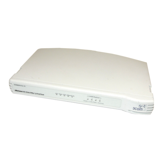
Page 16: Minimum System And Component Requirements
Figure 3 Router - Front Panel 1 Alert LED Orange Fast flash during self test. If self test fails the LED will remain on. Fast flash during software upgrade. Fast flash for software reset to the factory defaults. Fast flash for hardware reset to the factory defaults. - Page 17 If the LED is on it indicates that wireless networking is enabled. If the LED is flashing, the link is OK and data is being transmitted or received. If the LED is off, the Wireless LAN has been disabled in the Router, or there is a problem. Refer to Chapter 6 “Troubleshooting”.
- Page 18 Indicates the Router is powered on, the power adapter is working properly. 10 Power Adapter Socket Only use the power adapter that is supplied with this Router. Do not use any other adapter. 11 Reset Button If you want to reset your Router to factory default settings, and cannot access the web management interface (for example, due to a lost password), then you may use this button.
-
Page 19: Installing The Router
■ Router. A suitable location might be on top of a high shelf or similar furniture to optimize wireless connections to computers in both horizontal and vertical directions, allowing wider coverage. -
Page 20: Using The Rubber Feet
You will need two suitable screws to wall mount the unit. To do this: 1 Ensure that the wall you use is smooth, flat, dry and sturdy and make two screw holes which are 150 mm (5.9 in.) apart. -
Page 21: Powering Up The Router
ADSL port on your Router. When inserting an ADSL RJ-11 plug, be sure the tab on the plug clicks into position to ensure that it is properly seated. If you are using splitterless ADSL service, add low-pass filters between the ADSL wall jack and your telephones. - Page 22 ADSL line directly to your phone system. In this case you can connect your phones and computer directly to the incoming ADSL line, but you will have to add low-pass filters to your phones as shown below...
- Page 23 You have now completed the hardware installation of your Router. Next you need to set up your computers so that they can make use of the Router to communicate with the Internet. 3Com recommends that you perform the initial Router configuration from a computer that is directly connected to one of the LAN ports.
- Page 24 2: I HAPTER NSTALLING THE OUTER...
-
Page 25: Setting
The Router has the ability to dynamically allocate network addresses to the computers on your network, using DHCP. However, your computers need to be configured correctly for this to take place. To change the configuration of your computers to allow this, follow the instructions in this chapter. - Page 26 HAPTER ETTING OMPUTERS Figure 8 Local Area Properties Screen 6 Ensure that the options Obtain an IP address automatically, and Obtain DNS server address automatically are both selected as shown in Figure Click OK. Figure 9 Internet Protocol (TCP/IP) Properties Screen...
-
Page 27: Windows Xp
1 From the Windows Start Menu, select Settings > Control Panel. 2 Double click on Network. Select the TCP/IP item for your network card and click on Properties. 3 In the TCP/IP dialog, select the IP Address tab, and ensure that Obtain IP address automatically is selected. Click OK. Macintosh... -
Page 28: Disabling Pppoe And Pptp Client Software
Figure 10 Internet Properties Screen You may want to remove the PPPoE client software from your computer to free resources, as it is not required for use with the Router. Disabling Web Ensure that you do not have a web proxy enabled on your computer. -
Page 29: Running The Setup Wizard
Refer to Chapter 2 for details on how to do this. 2 Launch your Web browser on the computer. 3 Enter the following URL in the location or address field of your browser: http://192.168.1.1 (Figure 11). The Login screen displays. - Page 30 4: R HAPTER UNNING THE ETUP IZARD 4 To log in as an administrator, enter the password (the default password is admin) in the System Password field and click Log in (Figure 12). Figure 12 Router Login Screen 5 When you have logged in, if you are logging in for the first time, the Country Selection screen ■...
- Page 31 Router’s management interface. Figure 15 Password Screen 1 To change the current password, enter the password in the Current Password field. 2 Enter the new password in the New Password field, and enter it again in the Confirm New Password field.
-
Page 32: Setup Wizard - Change Password
HAPTER UNNING THE ETUP IZARD 3 Enter the time period in Login Timeout to set a maximum period of time for which the login session is maintained during inactivity (Default: 10 minutes). Setup Wizard - To ensure the security of your Router, it is recommended that you choose... -
Page 33: Setup Wizard - Connection Type
5 Click Next. Setup Wizard - The Connection Type screen allows you to set up the Router for the type Connection Type of Internet connection you have. Before setting up your connection type, have your account information from your ISP ready. - Page 34 UNNING THE ETUP IZARD PPPoE Mode To set up the Router for use with a PPP over Ethernet (PPPoE) connection, use the following procedure: Figure 19 PPPoE Screen 1 Enter your user name in the Username field. 2 Enter your password in the Password field.
- Page 35 Accessing the Setup Wizard PPPoA Mode To set up the Router for use with a PPP over ATM (PPPoA) connection, use the following procedure: Figure 20 PPPoA Screen 1 Enter your user name in the Username field. 2 Enter your password in the Password field.
- Page 36 3 Check all of your settings, and then click Next. The LAN Settings screen will then be displayed (refer to Figure 24). Routing Mode over ATM To set up the Router for use with an RFC1483 routed connection, use the following procedure: Figure 22 Routing Mode Screen...
- Page 37 24). Dynamic/Fixed IP in 1483 Bridge Mode (For Multiple PCs) For bridge mode to work, you need to assign an IP address to the Router. You can either configure the Router to obtain an IP address automatically from a DHCP server or assign a fixed or static IP address to it.
-
Page 38: Setup Wizard - Lan Settings
2 Select the On/Off button to turn on/turn off the DHCP function in the DHCP Server field. 3 Enter the client IP address range in the IP Pool Start Address and IP Pool End Address fields. 4 Click Next. The Wireless Settings screen will be displayed (refer to Figure 25). -
Page 39: Setup Wizard - Wireless Settings
1 Select the channel you want to use from the Channel drop-down menu. 2 Specify the SSID to be used by your Wireless Network in the SSID field. If there are other wireless networks in your area, you should give your... -
Page 40: Setup Wizard - Configuration Summary
Configuration will appear. Verify the configuration information of the Router and then Summary click Apply to save your settings. 3Com recommends that you print out this page for your records. Figure 26 Configuration Summary Screen Your Router is now configured and ready for use. -
Page 41: Configuring The
The main menu is located on the left side, as shown in Figure 27. When you click on an item from the main menu, the corresponding screen will then appear in the center. Welcome Screen The Welcome screen shows the current software information. -
Page 42: Lan Settings
■ Specify the IP address of 3Com NBX call processor. ■ The Router will also provide a list of all client computers connected to the Router. LAN Settings The LAN Settings screen is used to specify the LAN IP address of your Router, and to configure the DHCP server. -
Page 43: Dhcp Clients List
1 Enter the Router’s IP Address and Subnet Mask in the appropriate fields. The default IP address is 192.168.1.1. 2 If you want to use the Router as a DHCP Server, select On in the DHCP Server field. 3 Enter the IP address range in the IP Pool Start Address and IP Pool End Address fields. - Page 44 MAC Address — The Media Access Control (MAC) address of the ■ client’s network card. Client Type — Whether the client is connected to the Router by wired ■ or wireless connection. Check the Fix checkbox to permanently fix the IP address.
-
Page 45: Wireless Settings
You can enable or disable the wireless connection for your LAN. When disabled, no wireless PCs can gain access to either the Internet or other PCs on your wired or wireless LAN through this Router. Figure 31 Wireless Settings Screen... - Page 46 2 Select the wireless channel you want to use from the Channel drop-down menu. 3 Specify the SSID to be used by your wireless network in the SSID field. If there are other wireless networks in your area, you should give your wireless network a unique name.
-
Page 47: Encryption
This feature prevents any non-authorized party from reading or changing your data over the wireless network. Figure 33 Encryption Screen Select the wireless security mode that you want to use from the drop-down menu, and click Apply. There are five selections: Disabled (see page ■... - Page 48 Generate to generate the hex keys from the passphrase. For 64-bit WEP, you can enter up to four keys, in the fields Key 1 to Key 4. The radio button on the left hand side selects the key that is used in transmitting data.
- Page 49 Passphrase box, and then ■ click Generate to generate the hex keys from the passphrase. The WEP keys on each device on the wireless network must be identical. In 128-bit WEP mode, only one WEP key can be specified. 2 Click Apply.
- Page 50 Each client that connects to the network must use the same key. 5 If you want the key that you enter to be shown on the screen as a series of asterisks (*), then check the Hide PSK checkbox.
- Page 51 6 Enter the key for the RADIUS server in the RADIUS Key field. 7 By default, the WPA keys are changed every hour, but if you want to change this setting, you can do so by specifying the required time in the Re-key Interval field.
-
Page 52: Connection Control
Router via wireless link. Use the MAC Address Filtering List to quickly copy the MAC addresses of the current wireless clients into the list table. You can define up to 32 MAC addresses to the list. -
Page 53: Client List
Wireless Settings Client List You can view the list of all wireless clients that are connected to the Router. Figure 39 Client List Screen Click Refresh to update the list. WDS Settings The Router supports WDS (Wireless Distribution System). WDS enables one or more Access Points to rebroadcast received signals to extend range and reach, though this can affect the overall throughput of data. -
Page 54: Advance
5: C HAPTER ONFIGURING THE OUTER 3 Click Add to add the MAC address of the AP to the list, the add WDS screen will appear (refer to Figure 41). Figure 41 Add WDS screen Enter the MAC address(es) of one or more access points in the AP MAC Address table, and click Apply. -
Page 55: Profile
RTS Threshold: RTS stands for Request to Send, this parameter ■ controls what size data packet the low level RF protocol issues to an RTS packet. CTS Protection Mode: CTS stands for Clear to Send. CTS Protection ■... -
Page 56: Internet Settings
This feature is used to configure the parameters for your DSL connection. The information necessary to complete these screens should be obtained from your ISP. Check with your ISP first to find out what type of connection you should choose. - Page 57 2 Enter the IP address and Subnet Mask information provided by your ISP into the IP address and Subnet Mask fields. 3 Enter the user name assigned to you by your ISP in the Username field. And enter the password assigned to you by your ISP in the Password field.
- Page 58 8 To use the IPCP Subnet Mask Support for the DHCP clients, check the IPCP Subnet Populate DHCP Server checkbox. 9 Enter the VPI and VCI values provided by your ISP in the VPI and VCI fields. You can click Auto Search to automatically find out this information.
- Page 59 Select Yes, if your ISP assigns your IP address dynamically, and ■ proceed to next step. If your ISP has assigned you a fixed or static IP address, select No in ■ the IP assigned by ISP field. Then enter the IP address and Subnet Mask information provided by your ISP into the IP address and Subnet Mask fields.
- Page 60 Idle Time (Minutes) field. (Enter a value of 0 to disable this timeout). 6 Enter the MTU value supplied by your ISP. If you do not know this, leave it at the default value.
- Page 61 Figure 47 Bridge Mode Screen 1 Select Bridge Mode from the Protocol drop-down menu. 2 Enter the VPI and VCI parameters in the VPI and VCI fields. You can click Auto Search to automatically find out this information. 3 Select the encapsulation type (LLC or VC MUX) in the Encapsulation Type...
- Page 62 5: C HAPTER ONFIGURING THE OUTER 4 Select the type of Quality of Service that you want from the QoS Class drop-down menu. CBR (constant bit rate): the CBR service class is intended for ■ real-time applications, for example, those requiring tightly constrained delay and delay variation, such as voice and video applications.
- Page 63 5 If your ISP uses DHCP to automatically assign IP addresses, check the DHCP Client checkbox. 6 Enter the VPI and VCI parameters provided to you by your ISP in the VPI and VCI fields. You can click Auto Search to automatically find out this information.
- Page 64 5: C HAPTER ONFIGURING THE OUTER 8 Select the type of Quality of Service that you want from the QoS Class drop-down menu. CBR (constant bit rate): the CBR service class is intended for ■ real-time applications, for example, those requiring tightly constrained delay and delay variation, such as voice and video applications.
- Page 65 5 If your ISP uses DHCP to automatically assign IP addresses, check the DHCP Client checkbox. 6 Enter the VPI and VCI parameters provided by your ISP in the VPI and VCI fields. You can click Auto Search to automatically find out this information.
- Page 66 5: C HAPTER ONFIGURING THE OUTER 8 Select the type of Quality of Service that you want from the QoS Class drop-down menu. CBR (constant bit rate): the CBR service class is intended for ■ real-time applications, for example, those requiring tightly constrained delay and delay variation, such as voice and video applications.
-
Page 67: Dns
If your ISP provided you with specific DNS addresses to use, enter them into the appropriate fields on this screen and click Apply. Many ISPs do not require you to enter this information into the Router. If you are using a Static IP connection type, you may need to enter a specific DNS address and secondary DNS address for your connection to work properly. -
Page 68: Hostname & Clone Mac Address
The Hostname and MAC Address screen displays. Figure 52 Hostname and MAC Address Screen 1 Some ISPs require a host name. If your ISP has this requirement, enter the host name in the Host Name field. 2 Three different ways to configure the WAN MAC Address: If your ISP requires an assigned MAC address, enter the values in the ■... -
Page 69: Firewall
Figure 53 Firewall Screen To enable the firewall function: 1 Select the level of protection (High, Medium, or Low) that you desire from the Firewall level drop-down menu. 2 Click Apply. - Page 70 For high level of firewall protection, refer to Figure Figure 54 Low and Medium Level Firewall Protection Screen When abnormal network activity occurs, an alerting email will be sent out to you. Enter the following information to receive the email: Your E-mail Address ■...
- Page 71 When the timeout value expires, the Router drops the un-assembled packet, freeing that structure for use by another packet. TCP SYN wait - Defines how long the software will wait for a TCP ■ session to synchronize before dropping the session.
- Page 72 Maximum number of half-open fragmentation packets from the same host. Half-open fragmentation detect sensitive time period - Length of time ■ before a half-open fragmentation session is detected as half-open. Flooding cracker block time - Length of time from detecting a flood ■ attack to blocking the attack.
-
Page 73: Special Applications
A list of popular applications has been included to choose from. Select your application from the Popular Applications drop-down menu. Then select the row that you want to copy the settings to from the Copy To drop-down menu, and click Copy To. The settings will be transferred to the row that you specified. -
Page 74: Virtual Servers
2 Select the protocol type (TCP, UDP, or both TCP and UDP) from the drop-down menu. 3 Specify the public port that will be seen by clients on the Internet, and the LAN port which the traffic will be routed to. -
Page 75: Dmz
To put a computer in the DMZ: 1 Check the Enable 1-to-1 NAT checkbox. 2 Enter the last digits of the LAN IP address in the Client PC IP Address field. Enter the IP address (if known) that will be accessing the DMZ PC into the Public IP Address field, so that only the computer on the Internet at this address can access the DMZ PC without firewall protection. -
Page 76: Schedule Rule
2 Enter a name and comment for the schedule rule in the Name and Comment fields. 3 Specify the schedule rules for the required days and times - note that all times should be in 24 hour format. 4 Click Apply. -
Page 77: Pc Privileges
You can define the traffic type permitted or not-permitted to the Internet. Figure 61 PC Privileges Screen To edit or delete specific existing filtering rules, click on Edit or Delete for the appropriate filtering rule. To configure a new filtering rule: 1 Check the Enable Filtering Function checkbox. - Page 78 Web sites and keywords defined in this screen will not be filtered out. 5 Select the services to be blocked. A list of popular services is given on this screen, to block a particular service, check the appropriate Blocking checkbox.
-
Page 79: Url Filter
Firewall URL Filter To configure the URL filter feature, use the table on the URL Filter screen to specify the Web sites (www.somesite.com) and/or keywords you want to filter on your network. For example, entering a keyword of xxx would block access to any URL that contains the string xxx. - Page 80 ONFIGURING THE OUTER Content Filter You can use the list on the Content Filter screen to specify the type of content that you want to filter out. The Router comes with a 14-day free trial of the 3Com Content Filter Service (3CSBCFS).
-
Page 81: Server Control
Firewall 4 If you are not sure about your subscription status, click CHECK in Subscription Filtering Status to find out if you have a current, valid subscription. 5 Subjects are listed under Core Categories and Productivity Categories. You can define what content should be viewed/blocked using the Allow/Deny option. - Page 82 OUTER Figure 66 Server Control Add Server Screen 1 Enter a description in the Server Description field, and the IP address or IP address range into the Server IP Address fields. 2 Select the services that will be allowed. A list of popular services is given on this screen, to unblock a particular service, check the appropriate Allowed checkbox.
-
Page 83: Quality Of Service
Figure 67 QoS Settings Screen Define the minimum percentage of bandwidth for each type of traffic. Traffic Mapping You can define up to 16 rules to classify traffic into Diffserv forwarding groups and outgoing VCs in this screen. Figure 68 Traffic Mapping screen... -
Page 84: Traffic Statistics
69). Figure 69 Add New Traffic Class Rule Screen Traffic Statistics This screen shows the WAN outbound traffic statistics of all the Diffserv forwarding groups in the last 12 hours. This screen automatically updates every 5 minutes. Figure 70 Traffic Statistics Screen... -
Page 85: Advanced
ISP with the computers on your network. This function should only be disabled by advanced users, and if your ISP assigns you multiple IP addresses or you need NAT disabled for an advanced system configuration. If you have a single IP address and... - Page 86 IP address and receiving a response from the IP address, a hacker can determine that something of interest might be there. The Router can be set up so it will not respond to an Internet Control Message Protocol (ICMP) Ping from the outside. This heightens the level of security of your Router.
- Page 87 TCP Maximum Segment Size (MSS). However, this message may be blocked by some firewalls. When this occurs, the packet is dropped. To allow the message to go through the firewall, enable MSS Clamping. MSS clamping will make Internet Connection Sharing set the MSS value low enough to match the external interface.
-
Page 88: Static Routes
To change an existing entry, click Edit. To delete an entry, click Delete. Figure 72 Static Routes Screen This screen shows a list of current static route entries. For each entry, the following information is displayed: Index — the index of the entry. -
Page 89: Rip
3 Select the Operation Mode: Disabled — RIP is not enabled for the WAN or LAN interface. ■ Enabled — RIP is enabled for the WAN or LAN interface. The router ■ will transmit RIP update information to other RIP-enabled devices. -
Page 90: Ddns
None — Switches off authentication on the specified interface. ■ Password — An unencrypted text password that needs to be set on all ■ RIP-enabled devices connected to this Router. RIP information is not shared between devices whose passwords do not match. - Page 91 Advanced Before you set up DDNS, you must obtain an account, password or key and static domain name from your DDNS provider. DDNS is disabled by default. Figure 74 Dynamic Domain Name Server (DDNS) Screen 1 Check Enable DDNS. 2 Select the provider, and then enter the necessary information provided by your DDNS provider.
-
Page 92: Snmp
Your SNMP management agent needs to be configured with this name so that it can communicate with your Router. 2 In the Access column, select Read to allow the management agent to collect data (for example, bandwidth usage) from your Router. Select Write to allow the management agent to change the configuration of your Router. -
Page 93: Syslog
To configure SNMP traps: 1 In the IP Address field, enter the IP address of the PC to which you want your Router to send status messages. 2 In the Community field, enter the name of the SNMP communication channel to which you want your Router to send status messages. -
Page 94: Proxy Arp
ONFIGURING THE OUTER Proxy ARP Proxy ARP is the technique in which one host, usually a Router, answers ARP requests intended for another machine. By "faking" its identity, the Router accepts responsibility for routing packets to the "real" or intended destination. -
Page 95: System Tools
Restart Router Sometimes it may be necessary to restart (or reboot) the Router. Restarting the Router from this screen will not delete any of your configuration settings. Click the Restart the Router button to restart the Router. -
Page 96: Upgrade
Backup Configuration — You can save your current configuration by ■ clicking the Backup button. Saving your configuration will allow you to restore it later if your settings are lost or changed. It is recommended that you backup your current configuration before performing a firmware update. -
Page 97: Time Zone
Enable Daylight Saving. The system clock may not update immediately. Allow at least 15 minutes for the Router to contact the time servers on the Internet and get a response. You cannot set the clock yourself. -
Page 98: Ping
1 Enter the IP address or domain name in the IP Address or Domain Name field, and click Ping. 2 Select from the Number of times to Ping drop-down menu. 3 The Router keeps a log of the ping test, click Clear Log to delete the records. -
Page 99: Traceroute
Figure 83 Traceroute Screen 1 Enter the IP address or domain name in the IP Address or Domain Name field, and click Traceroute. 2 The Router keeps a log of the traceroute test, click Clear Log to delete the records. -
Page 100: Dns Lookup
Figure 84 DNS Lookup Screen 1 Enter the IP address or domain name in the IP Address or Domain Name field, and click Dns lookup. 2 The Router keeps a log of the DNS lookup test, click Clear Log to delete the records. -
Page 101: Status And Logs
Status and Logs Status and Logs You can use the Status Screen to view version numbers for your Router’s software and hardware and check the status of connections to WAN, LAN and WLAN interfaces. Status Figure 85 Status Screen This screen shows Router status and statistics. -
Page 102: Atm Pvc Status
■ Click Renew to obtain the IP address from your ISP. ■ Routing Table This screen displays details for the default routing used by your Router and any routing created using Static Routing or RIP. Figure 88 Routing Table Screen... -
Page 103: Logs
Figure 89 Logs Screen Click Help to view the help file. ■ Click Save to save the log to the hard disk as a text file. When ■ prompted for a location to save the file to, specify a filename and location, and then click OK. -
Page 104: Support/Feedback
3Com. Support Figure 90 Support Screen This screen shows support information. Feedback To provide feedback to 3Com, please click Provide Feedback, and this will connect you to the 3Com Web site. Figure 91 Feedback Screen This screen shows feedback information. -
Page 105: Troubleshooting
Some network interfaces may not be correctly initialized until the start-up procedure has completed. If the link status LED does not illuminate for a port that is connected, ■ check that you do not have a faulty cable. Try a different cable. -
Page 106: Connecting To The Internet
1 Power off the Router. 2 Disconnect all your computers and the telephone line from the Router. 3 Re-apply power to the Router, and wait for it to finish booting up. -
Page 107: Wireless Networking
4 Press and hold the Reset button on the rear panel (see “The rear panel (Figure 4) of the Router contains four LAN ports, one ADSL port, a reset button, a power OK LED, and a power adapter socket.” page 16) for 5 seconds. - Page 108 As the signal quality weakens then the speed falls back to a lower speed. The speeds supported by 802.11g are 54 Mbps, 48 Mbps, 36 Mbps, 24 Mbps, 18 Mbps, 12 Mbps and 6 Mbps. The speeds supported by 802.11b are 11 Mbps, 5.5 Mbps, 2 Mbps and 1 Mbps.
-
Page 109: Recovering From Corrupted Software
192.168.1.1. Follow the instructions below to upload a new copy of the system software to a Router unit in this state. Ensure that one of your computers has a copy of the new software image file stored on its hard disk or available on CD-ROM. -
Page 110: Frequently Asked Questions
Does the Router support virtual private networks (VPNs)? The Router supports VPN passthrough, which allows VPN clients on the LAN to communicate with VPN hosts on the Internet. It is also possible to set up VPN hosts on your LAN that clients elsewhere on the Internet can connect to, but this is not a recommended configuration. -
Page 111: Ip Addressing
However, an IP address alone is not enough to make your device operate. In addition to the IP address, you need to set a subnet mask. All networks are divided into smaller sub-networks and a subnet mask is a number that enables a device to identify the sub-network to which it is connected. - Page 112 A: IP A PPENDIX DDRESSING For your network to work correctly, all devices on the network must have: The same sub-network address. ■ The same subnet mask. ■ The only value that will be different is the specific host device number.
-
Page 113: How Does A Device Obtain An Ip Address And Subnet Mask
PC 4 192.168.002.230 255.255.0.0 Router 192.168.002.72 255.255.0.0 How does a Device There are three different ways to obtain an IP address and the subnet Obtain an IP mask. These are: Address and Subnet Dynamic Host Configuration Protocol (DHCP) Addressing ■ Mask? Static Addressing ■... - Page 114 IP address at random from the industry standard subnet of 169.254.x.x (with a subnet mask of 255.255.0.0). If two devices allocate themselves the same address, the conflict is detected and one of the devices allocates itself a new address.
-
Page 115: Technical Specifications
LAN connection — four 10 Mbps/100 Mbps dual speed Ethernet ports (10BASE-T/100BASE-TX) WLAN Interfaces Standard IEEE 802.11g, Direct Sequence Spread Spectrum (DSSS) Transmission rate: 54 Mbps, automatic fallback to 48, 36, 24, 18, 12, or 6 Mbps Maximum channels: 13 Range up to 304.8m (1000ft) Sensitivity: 6, 12, 18, 24, 36, 48 Mbps: -85 dBm;... -
Page 116: Standards
B: T PPENDIX ECHNICAL PECIFICATIONS Operating Temperature 0 °C to 40 °C (32 °F to 105 °F) Power 8VA, 25 BThU/hr Humidity 0% to 90% (non-condensing) humidity Dimensions Width = 220 mm (8.7 in.) ■ Depth = 133 mm (5.2 in.) ■... - Page 117 ■ Unix ■ Ethernet Performance The Router complies to the IEEE 802.3i, u and x specifications. Cable Specifications The Router supports the following cable types and maximum lengths: Category 3 (Ethernet) or Category 5 (Fast Ethernet or Dual Speed ■...
- Page 118 B: T PPENDIX ECHNICAL PECIFICATIONS...
-
Page 119: Safety Information
WARNING: The Router generates and uses radio frequency (rf) energy. In some environments, the use of rf energy is not permitted. The user should seek local advice on whether or not rf energy is permitted within the area of intended use. - Page 120 Erkundigen Sie sich bei den zuständigen Stellen, ob die Verwendung von Funkfrequenz in dem Bereich, in dem der Bluetooth Access Point eingesetzt werden soll, erlaubt ist. VORSICHT: Bei der Installation und beim Ausbau des Geräts ist mit höchster Vorsicht vorzugehen. VORSICHT: Aufgrund von internationalen Sicherheitsnormen darf das Gerät nur mit dem mitgelieferten Netzadapter verwendet werden.
- Page 121 électrique remis avec cet appareil. AVERTISSEMENT: La prise secteur doit se trouver à proximité de l’appareil et son accès doit être facile. Vous ne pouvez mettre l’appareil hors circuit qu'en débranchant son cordon électrique au niveau de cette prise.
- Page 122 AVERTISSEMENT: Il n’y a pas de parties remplaceables par les utilisateurs ou entretenues par les utilisateurs à l’intérieur du moyeu. Si vous avez un problème physique avec le moyeu qui ne peut pas être résolu avec les actions de la résolution des problèmes dans ce guide, contacter votre fournisseur.
-
Page 123: Nd Ser Software License Agreement
Technical Data. In addition to the above, the Product may not be used, exported or re-exported (i) into or to a national or resident of any country to which the U.S. has embargoed; or (ii) to any one on the U.S. Commerce Department's Table of Denial Orders or the U.S. Treasury Department's list of Specially Designated Nationals. - Page 124 The Software is delivered as "Commercial Computer Software" as defined in DFARS 252.227-7014 (June 1995) or as a commercial item as defined in FAR 2.101(a) and as such is provided with only such rights as are provided in this Agreement, which is 3Com's standard commercial license for the Software.
-
Page 125: Upport For Your Product
Warranty and other service benefits start from the date of purchase, so it Product is important to register your product quickly to ensure you get full use of the warranty and other service benefits available to you. Warranty and other service benefits are enabled through product registration. -
Page 126: Troubleshoot Online
Software Updates you must first register your product on the 3Com Web site at http://eSupport.3com.com/ First time users will need to apply for a user name and password. A link to software downloads can be found at , or http://eSupport.3com.com/ under the Product Support heading at www.3com.com... -
Page 127: Contact Us
Contact Us To send a product directly to 3Com for repair, you must first obtain a return authorization number (RMA). Products sent to 3Com, without authorization numbers clearly marked on the outside of the package, will be returned to the sender unopened, at the sender’s expense. If your... - Page 128 Switzerland 0800 553 072 Italy 800 879489 U.K. 0800 096 3266 You can also obtain support in this region using the following URL: http://emea.3com.com/support/email.html Latin America Telephone Technical Support and Repair Antigua Barbuda AT&T +800 988 2112 Guadalupe AT&T +800 998 2112...
- Page 129 Contact Us Country Telephone Number Country Telephone Number US and Canada Telephone Technical Support and Repair 1 800 876 3266...
- Page 130 E: O PPENDIX BTAINING UPPORT FOR RODUCT...
- Page 131 The rates will switch automatically depending on range and environment. 802.11g The IEEE specification for wireless Ethernet which allows speeds of up to 54 Mbps. The standard provides for 6, 12, 24, 36, 48 and 54 Mbps data rates. The rates will switch automatically depending on range and environment.
- Page 132 Ethernet is 100 Mbps. The bandwidth for 802.11b wireless is 11Mbps. Category 3 Cables One of five grades of Twisted Pair (TP) cabling defined by the EIA/TIA-586 standard. Category 3 is voice grade cable and can only be used in Ethernet networks (10BASE-T) to transmit data at speeds of up to 10 Mbps.
- Page 133 Encryption A method for providing a level of security to wireless data transmissions. The Router uses two levels of encryption; 40/64 bit and 128 bit. 128 bit is a more powerful level of encryption than 40/64 bit. ESSID Extended Service Set Identifier.
- Page 134 Infrastructure mode Infrastructure mode is the wireless configuration supported by the Router. You will need to ensure all of your clients are set up to use infrastructure mode in order for them to communicate with the Access Point built into your Router.
- Page 135 Media Access Control Address. Also called the hardware or physical address. A Layer 2 address associated with a particular network device. Most devices that connect to a LAN have a MAC address assigned to them as they are used to identify other devices in a network. MAC addresses are 6 bytes long.
- Page 136 A subnet mask, which may be a part of the TCP/IP information provided by your ISP, is a set of four numbers configured like an IP address. It is used to create IP address numbers used only within a particular network (as opposed to valid IP address numbers recognized by the Internet, which must assigned by InterNIC).
- Page 137 URL Filter A URL Filter is a feature of a firewall that allows it to stop its clients form browsing inappropriate Web sites. Wide Area Network. A network that connects computers located in geographically separate areas (for example, different buildings, cities, or countries).
- Page 138 LOSSARY WLAN Wireless Local Area Network. A WLAN is a group of computers and devices connected together by wireless in a relatively small area (such as a house or office). Wi-Fi Protected Access. A dynamically changing encryption mechanism for wireless networking. Encryption strength is 256 bit.
- Page 139 20 cm (approximately 8 in.). The installer of this radio equipment must ensure that the antenna is located or pointed such that it does not emit RF field in excess of Health Canada limits for the general population; consult Safety Code 6, obtainable from Health Canada's website www.hc-sc.gc.ca/rpb.
- Page 140 Pour empecher que cet appareil cause du brouillage au service faisant l'objet d'une licence, il doit etre utilize a l'interieur et devrait etre place loin des fenetres afin de Fournier un ecram de blindage maximal. Si le matriel (ou son antenne d'emission) est installe a l'exterieur, il doit faire l'objet d'une licence.
- Page 141 Intended use: ADSL 802.11g/b Firewall Router For connection to ADSL networks NOTE: To ensure product operation is in compliance with local regulations, select the country in which the product is installed. Refer to 3CRWDR101A-75 User Guide. Česky 3Com Coporation tímto prohlašuje, ze tento RLAN [Czech] device je ve shodě...
- Page 142 A copy of the signed Declaration of Conformity can be downloaded from the Product Support web page for the 3Com OfficeConnect ADSL Wireless 54 Mbps 11g Firewall Router at http://www.3Com.com. Also available at http://support.3com.com/doc/WL-552_EU_DOC.pdf.
- Page 143 前項合法通信,指依電信規定作業之無線電信。 低功率射頻電機須忍受合法通信或工業, 科學及醫療用 電波輻射性電機設備之干擾。 RTTE01: 1. 本機限在不干擾合法電台與不受被干擾保障條件下於室內使用 2. 為減少電波干擾,請妥適使用...
- Page 145 Dynamic Domain Server (DDNS) Screen 70 128-bit WEP Screen 46 Dynamic IP Address 34 1483 Bridge Mode 55 Dynamic/Fixed IP for Bridge Mode Screen 35, 55 64-bit WEP Screen 47 DYNDNS 70 Access Control Screen 62 Editing DHCP Clients List Screen 42...
- Page 146 NIC 14 Restart Router Screen 73 Wireless Configuration Screen 43 RFC 1483 Bridged Mode 32, 53 Wireless Settings Screen 31, 32, 33, 35, 36, 43 RFC 1483 Routed Mode 34 Wireless WDS Settings Screen 49 RIP (Routing Information Protocol) 57...