Haier AE122FCAKA Instruction Manual
H-mrv ceiling concealed type air conditioner indoor unit
Hide thumbs
Also See for AE122FCAKA:
- Instruction manual (38 pages) ,
- Service manual (174 pages) ,
- Operation & installation manual (20 pages)
Table of Contents
Advertisement
Quick Links
CEILING CONCEALED TYPE AIR CONDITIONER INDOOR UNIT
INSTRUCTION
MANUAL
0010573331
Please read this manual carefully before use.
Please keep it attentively for future use.
AE072FCAKA
AE092FCAKA
AE09~212FCAKA
AE072FCAKA
AE242FCAKA
Ceiling Concealed Type Room Air Conditioner
AE122FCAKA
AE142FCAKA
Contents
Before Application
Cautions
Part Description
Important Points of Safety
Operating Instructions
AUTO,COOL, DRY,HEAT Operation
TIME Operation
Sleep Function
Health Function
Maintenance
Trouble Shooting
When Fault Occurs
Notice to Users
Indoor Unit Installation
Installation Precautions
Installation Procedure
Malfunction
Installation Check and Trial Run
H-MRV
AE182FCAKA
AE212FCAKA
AE242FCAKA
1-2
3-8
9-11
12
13-14
15
16
17-18
19
20
21-22
23-33
34-35
36
Advertisement
Table of Contents

Related Manuals for Haier AE122FCAKA


Summary of Contents for Haier AE122FCAKA
- Page 1 CEILING CONCEALED TYPE AIR CONDITIONER INDOOR UNIT H-MRV Ceiling Concealed Type Room Air Conditioner AE072FCAKA AE122FCAKA AE182FCAKA INSTRUCTION AE092FCAKA AE142FCAKA AE212FCAKA MANUAL AE242FCAKA Contents Before Application Cautions Part Description AE09~212FCAKA Important Points of Safety 9-11 Operating Instructions AUTO,COOL, DRY,HEAT Operation...
- Page 2 Cautions...
- Page 3 Cautions Rated Maximum Minimum DB C Indoor WB C Cooling DB C outdoor WB C DB C Indoor Heating 14.5 WB C outdoor DB C WB C...
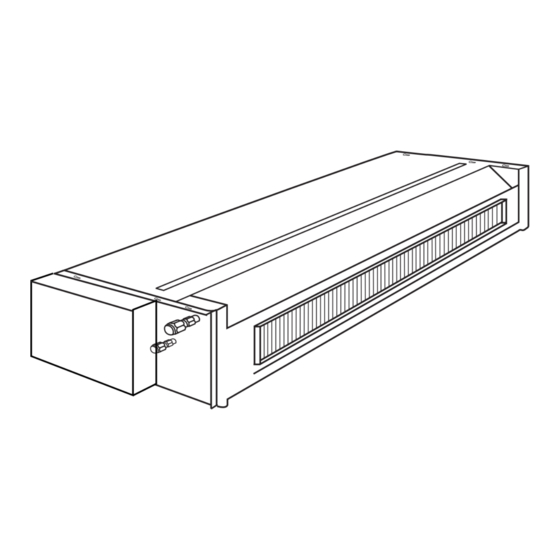
- Page 4 AE092FCAKA , AE122FCAKA , AE142FCAKA , AE182FCAKA , AE212FCAKA have the Return air box (see the following picture) when shipping from the factory and they are back-side return air. During the installation, also can be changed to Down-side Return air according to the user's need.
- Page 5 Wire remote controlller AUTO Remote controlller (1) Remote controlller is an accessory, to be ordered extrally fig(1) The right figure is a remote controller, which can be used T E M P on AE072FCAKA(remote control), AE092FCAKA(remote HEALTH control), AE122FCAKA(remote control), AE142FCAKA...
- Page 6 Calibration of clock When turning on the unit for the first time, the clock should be calibrated. The method of calibration is: 1.Press ì Clockî button, the Clock display ì AMî ì PMî will flash.
- Page 7 When operating the remote controller in an area where electronically controlled lights are installed or wireless handsets are used, move closer to the indoor unit as the function of the remote controller might be affected by signals from this equipment.
- Page 8 Note: 1.After change the battery, working condition resume as follows: Working mode:cooling Temp. 26 C Timming mode: normal Air speed: Auto 2.The units used in this manual no 8 18 functions. The health key can only control the negative generator.
-
Page 9: Clock Set
The battery compartment lid is reinstalled in the reverse sequence. Display review Press the button to see if batteries are properly fitted. If no display appears, refit the batteries. Caution: If the remote controller does not operate as designed after fitting new batteries of the same type, press the Reset button (marked ) with a pointed article. -
Page 10: Important Points Of Safety
Comply with the following important points of safety. Put these important points of attention and suggestions nearby and convenient for reference in need. Hand over this instruction manual to new user if you resell this machine. Warning... - Page 11 Important Points of Safety Warning Avoid your body being blown If something abnormal (e.g.: burnt directly by cold wind for long smell etc.) occurs, stop running the period, otherwise your health machine, shut down the manual may be affected. power switch and contact after service.
- Page 12 * DONíT operate switch with wet hand. Electric shock may occur * Donít put vases containing water otherwise. or other else on the unit assembly. Otherwise, the machine may be immersed internally and result in bad electric insulation causing electric shock.
-
Page 13: Operating Instructions
Fan running: The AC only have air supply running no cooling and heating running at the condition, AC can't have auto air supply running, and can't display the setting temperature value on the LCD. During the heating running, after start the AC, in order to prevent cooled air, AC can stop for a while before send heat air. -
Page 14: Timer Operation
To cancel TIMER mode Timer mode indicator lights up. Just press TIMER button several times until TIMER mode disappears. According to the seting timing open, close sequence, can realize first open then colse the unit or first close then open the unit. Hints: Wire controller possesses memory function, when use TIMER mode next time, just press SET button after mode selecting if timer setting is the same as previous one. -
Page 15: Timer On/Off
AM refers to morning and PM to afternoon. To cancel TIMER mode Just press TIMER button several times until TIMER mode disappears. According to the Time setting sequence of TIMER ON or TIMER OFF, either Start-Stop or Stop-Start can be achieved. -
Page 16: Sleep Function
After another hour the temp. rises 1 and then run continuously for another 6hrs' and then close. The actual temp. is higher than the setting one which is to prevent from being too cool to your sleep. -
Page 17: Health Function
Notes: When a power failure suddenly occurs during the air conditioner is working after the power failure compensation is set, if the air conditioner will not be used for a long time, please cut off the power supply to prevent its operation from being resumed after the power is supplied again, or press the "Switch On/Off"... -
Page 18: Troubleshooting
During operation, mist or steam are During COOL or DRY operation, the unit blown out. may blow out a thin mist. This is the con- densate water mist caused by sudden co- oling of the indoor air blown out from the indoor unit. - Page 19 Before asking for after-service to an authorized service center, please check your air conditioner for the following items The system couldnt start Is current leakage breaker...
-
Page 20: When Fault Occurs
If, after the above checks and the corresponding corrective actions, the system remains abnormal operation, or the following facts appear, please turn off the air conditioner and then contact the local authorized service center. Frequent open of fuse or breaker. -
Page 21: Notice To Users
Notice to Users Notice to users To ensure proper operation of the system, the user shall follow this instruction manual to install the unit. When handling the air conditioner, please be care not to scratch the case surface. This instruction manual describes the installation method aided with the installation tools specified by manufacturer . -
Page 22: Installation Precautions
The wiring work shall be done by a qualified person and referred to the " technical standard of electric equipment" , "indoor wiring regulation" and what the manual specified. Do use special circuit. If the capacity of the circuit is not enough or bad work, electric shock, fire and other accidents will happen. -
Page 23: Installing Tools
A current leakage breaker must be installed. The connection method of power cord is " Y " type. If the power flexible cord is damaged, it shall be replaced by the manufacturer or its service department or similar qualified technician so as to avoid risks. -
Page 24: Installation Procedure
2. Before drilling check that there is no pipe or reinforcing bar just behind the drilling position. Drilling shall avoid at positions with electric wire or pipe. 3. Mount the unit on a strong and horizontal building roof. If the base is not firm, it will cause noise, vibration or leakage (see Figure 6). -
Page 25: Installation Of Indoor Unit
Return air Each air return and supply duct should fix to the floor precast slab by using an iron stand. Use glue to seal the interface closely. Recommend the distance between the air return duct and the wall is more than 150mm. - Page 26 It should be also connected to its respective air diffuser separately. See Fig.1. Adjust the wind speed of each air diffuser outlet to keep in line on the whole, so as to meet a demand of the air conditioner in the room.
- Page 27 Suspension screw Hanging of the indoor unit l Fasten the nut on the suspension screw and then hang the suspension screw in the T slot of the suspension part of the unit. l Aided with a level meter, adjust level of the unit within 5 mm.
-
Page 28: Installation Of Remote Controller
Signal wire is self-provided by user. 5. Replace the upper cover of wire controller Be careful not to hold down the wiring. Hint 1. Power supply switch and signal wire should be prepaired by the user. 2. Don't touch PCB with hand. - Page 29 Because of the temperature sensitive device, do not install the receive display at straight sunlight place, either in front of air outlet grill, for it is effected greatly from cool air and heat air, the receive display is at least 20mm distance to the air outlet grill.
-
Page 30: Drain Pipe
S type elbow, otherwise abnormal sound will be produced. The horizontal length of the drain pipe shall be less than 20 m. In case of long pipe, suppo- rts shall be provided every 1.5 ñ 2m to prevent wavy form. -
Page 31: Refrigerant Piping
Installation Procedure efrigerant piping Allowable pipe length and drop These parameters differ according to the outdoor unit. See the instruction manual attached with the outdoor unit for details. Pipe material and size Pipe material Phosphorus deoxidized copper seamless pipe (TP... - Page 32 Open all valves Open all the valves on the outdoor unit. Gas leakage detection Check with a leakage detector or soap water that if there is gas leakage at the pipe connections and bonnets. Insulation treatment Conduct insulation treatment on both the gas side and liquid side of pipes respectively.
-
Page 33: Electric Wiring
A current leakage breaker shall be installed, otherwise it electric shock would happen easily. If the power cord is damaged, it must be replaced by the manufacturer or its service center or similar personnel to avoid risks. The power supply to the indoor unit shall be laid in complying with the operational instruction manual. -
Page 34: Field Setting
Insert from outside the connection wire and signal transmission wire through the wall hole with pipeline already arranged. Pull out the front ends of connection wire and signal wire and make a circle on the signal wire. Connect the connection wire according to the connection method and indoor and outdoor wiring diagram. - Page 35 Water temp. sensor is abnormal Outdoor unit malfunction display code (When the wire remote controller display E1,can check the indoor unit control board LED1 or the outdoor unit control board LED1 Outdoor unit control board LED (ALARMA or ALARMB)).
- Page 36 Malfunction Remote controller Timer and Operation indicator malfunction code When the unit running, Timer indicator flash stand for indoor unit malfunction operation indicator flashing stand for outdoor unit malfunction 1. Indoor unit malfunction Timer indicator Indoor unit malfunction Flashing times...