ASROCK FATAL1TY P67 PERFORMANCE User Manual
Hide thumbs
Also See for FATAL1TY P67 PERFORMANCE:
- Quick installation manual (314 pages) ,
- User manual (83 pages) ,
- Installation manual (15 pages)
Table of Contents
Advertisement
Advertisement
Table of Contents

Related Manuals for ASROCK FATAL1TY P67 PERFORMANCE


Summary of Contents for ASROCK FATAL1TY P67 PERFORMANCE
- Page 1 Fatal1ty P67 Performance Series User Manual Version 1.0 Published April 2011...
- Page 2 Fatal1ty Story Who knew that at age 19, I would be a World Champion PC gamer. When I was 13, I actually played competitive billiards in professional tournaments and won four or five games off guys who played at the highest level. I actually thought of making a career of it, but at that young age situations change rapidly.
- Page 3 I’ve preached since I began competing. I don’t want to worry about my equipment. I want to be there – over and done with - so I can focus on the game. I want it to be the fastest and most stable computer equipment on the face of the planet, so quality is what Fatal1ty Brand products represent.
- Page 4 We assumes no responsibility for any errors or omissions that may appear in this manual. With respect to the contents of this manual, We do not provide warranty of any kind, either expressed or implied, including but not limited to the implied warranties or conditions of merchantability or fi...
-
Page 5: Table Of Contents
..... 34 2.13 Hot Plug and Hot Swap Functions for SATA / SATAII HDDs ................35 2.14 Hot Plug and Hot Swap Functions for SATA3 HDDs ..35 2.15 SATA / SATAII / SATA3 HDD Hot Plug Feature and Operation Guide ............ - Page 6 3.4.5 Super IO Confi guration ........57 3.4.6 ACPI Confi guration..........58 3.4.7 USB Confi guration ..........59 3.5 Hardware Health Event Monitoring Screen ....60 3.6 Boot Screen ..............61 3.7 Security Screen ............. 62 3.8 Exit Screen ..............63 4 Software Support ..........
-
Page 7: Introduction
In this manual, chapter 1 and 2 contain introduction of the motherboard and step- by-step guide to the hardware installation. Chapter 3 and 4 contain the confi guration guide to BIOS setup and information of the Support CD. -
Page 8: Specifi Cations
Specifications Platform - ATX Form Factor: 12.0-in x 9.6-in, 30.5 cm x 24.4 cm - All Solid Capacitor design (100% Japan-made high-quality Conductive Polymer Capacitors) ® - Supports 2nd Generation Intel Core i7 / i5 / i3 in LGA1155 Package - Advanced V8 Power Phase Design ®... - Page 9 AHCI and "Hot Plug" functions (SATA3_1 connector is shared with eSATA3 port) USB3.0 - 2 x USB 3.0 ports by Etron EJ168A, support USB 1.0/2.0/3.0 up to 5Gb/s Connector - 4 x SATA2 3.0 Gb/s connectors, support RAID (RAID 0,...
- Page 10 Overclocking may affect your system stability, or even cause damage to the components and devices of your system. It should be done at your own risk and expense. We are not responsible for possible damage caused by overclocking.
- Page 11 Instant Flash. Just launch this tool and save the new BIOS fi le to your USB fl ash drive, fl oppy disk or hard drive, then you can update your BIOS only in a few clicks without preparing an additional fl...
- Page 12 11. On/Off Play Technology allows users to enjoy the great audio experience from the portable audio devices, such like MP3 player or mobile phone to your PC, even when the PC is turned off (or in ACPI S5 mode)! This motherboard also provides a free 3.5mm audio cable (optional) that en- sures users the most convenient computing environment.
-
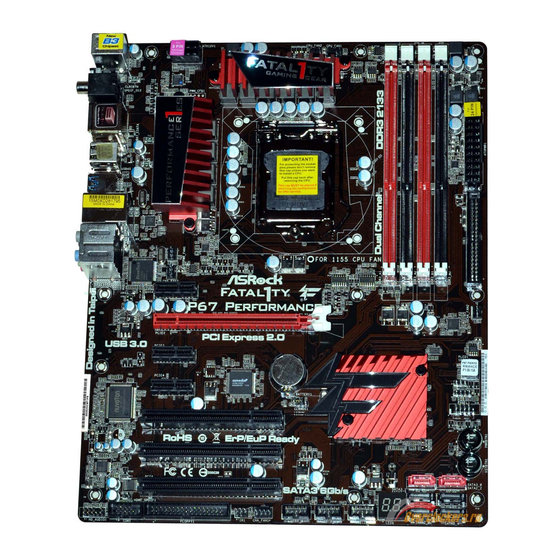
Page 13: Motherboard Layout
(HDMI_SPDIF1, Black) System Panel Header (PANEL1, Black) PCI Slots (PCI1-3) Intel P67 Chipset PCI Express 2.0 x1 Slot (PCIE4, Black) Power Switch (PWRBTN) PCI Express 2.0 x1 Slot (PCIE3, Black) Reset Switch (RSTBTN) PCI Express 2.0 x16 Slot (PCIE2, Red) SATA3 Connector (SATA3_1, Red) PCI Express 2.0 x1 Slot (PCIE1, Black) -
Page 14: I/O Panel
Central / Bass (Orange) Clear CMOS Switch (CLRCBTN) Line In (Light Blue) PS/2 Keyboard Port (Purple) * There are two LED next to the LAN port. Please refer to the table below for the LAN port LED indications. LAN Port LED Indications ACT/LINK... - Page 15 To enable Multi-Streaming function, you need to connect a front panel audio cable to the front panel audio header. After restarting your computer, you will fi nd “Mixer” tool on your system. Please select “Mixer ToolBox” , click “Enable playback multi-streaming”, and click “ok”.
-
Page 16: Installation
Chapter 2: Installation This is an ATX form factor (12.0" x 9.6", 30.5 x 24.4 cm) motherboard. Before you install the motherboard, study the confi guration of your chassis to ensure that the motherboard fi ts into it. Make sure to unplug the power cord before installing or removing the motherboard. -
Page 17: Cpu Installation
Before you insert the 1155-Pin CPU into the socket, please check if the CPU surface is unclean or if there is any bent pin on the socket. Do not force to insert the CPU into the socket if above situation is found. Other- wise, the CPU will be seriously damaged. - Page 18 1155-Pin CPU For proper inserting, please ensure to match the two orientation key notches of the CPU with the two alignment keys of the socket. Step 3-3. Carefully place the CPU into the socket by using a purely vertical mo- tion.
-
Page 19: Installation Of Heatsink And Cpu Fan
Installation of CPU Fan and Heatsink This motherboard is equipped with 1155-Pin socket that supports Intel 1155-Pin CPU. Please adopt the type of heatsink and cooling fan compliant with Intel 1155- Pin CPU to dissipate heat. Before you installed the heatsink, you need to spray thermal interface material between the CPU and the heatsink to improve heat dis- sipation. -
Page 20: Installation Of Memory Modules (Dimm)
fi guration, you always need to install identical (the same brand, speed, size and chip-type) DDR3 DIMM pair in the slots of the same color. In other words, you have to install identical DDR3 DIMM pair in Dual Channel A (DDR3_A1 and DDR3_B1;... - Page 21 DIMMs or the system components. Step 1. Unlock a DIMM slot by pressing the retaining clips outward. Step 2. Align a DIMM on the slot such that the notch on the DIMM matches the break on the slot. notch break...
-
Page 22: Expansion Slots (Pci And Pci Express Slots)
2.6 Expansion Slots (PCI and PCI Express Slots) There are 3 PCI slots and 4 PCI Express slots on this motherboard. PCI slots: PCI slots are used to install expansion cards that have the 32-bit PCI interface. PCIE slots: PCIE1 / PCIE3 / PCIE4 (PCIE x1 slot; Black) is used for PCI Express cards with x1 lane width cards, such as Gigabit LAN card, SATA2 card, etc. -
Page 23: Jumpers Setup
CMOS when you just fi nish updating the BIOS, you must boot up the system fi rst, and then shut it down before you do the clear-CMOS ac- tion. Please be noted that the password, date, time, user default profi le, 1394 GUID and MAC address will be cleared only if the CMOS battery is removed. -
Page 24: Onboard Headers And Connectors
FDD connector (33-pin FLOPPY1) (see p.13 No. 30) the red-striped side to Pin1 Note: Make sure the red-striped side of the cable is plugged into Pin1 side of the connector. Primary IDE connector (Black) (39-pin IDE1, see p.13 No. 8) - Page 25 HDA to function correctly. Please follow the instruction in our manual and chassis manual to install your system. 2. If you use AC’97 audio panel, please install it to the front panel audio header as below: A.
- Page 26 Connect to the power status indicator on the chassis front panel. The LED is on when the system is operating. The LED keeps blinking when the sys- tem is in S1 sleep state. The LED is off when the system is in S3/S4 sleep state or powered off (S5).
- Page 27 Though this motherboard provides 4-Pin CPU fan (Quiet Fan) support, the 3-Pin CPU fan still can work successfully even without the fan speed control function. If you plan to connect the 3-Pin CPU fan to the CPU fan connector on this motherboard, please connect it to Pin 1-3.
- Page 28 Though this motherboard provides 8-pin ATX 12V power connector, it can still work if you adopt a traditional 4-pin ATX 12V power supply. To use the 4-pin ATX power supply, please plug your power supply along with Pin 1 and Pin 5.
-
Page 29: Smart Switches
2.9 Smart Switches The motherboard has three smart switches: power switch, reset switch and clear CMOS switch, allowing users to quickly turn on/off or reset the sytem clear the CMOS values. Power Switch Power Switch is a smart switch, allowing users to quickly turn... -
Page 30: Dr. Debug
2.10 Dr. Debug Dr. Debug is used to provide code information, which makes troubleshooting even easier. Please see the diagrams below for reading the Dr. Debug codes. Status Code Description 0x00 Not used 0x01 Power on. Reset type detection (soft/hard) - Page 31 Internal CPU error 0x5B reset PPI is not available 0x5C-0x5F Reserved for future AMI error codes 0xE0 S3 Resume is stared (S3 Resume PPI is called by the DXE IPL) 0xE1 S3 Boot Script execution 0xE2 Video repost 0xE3 OS S3 wake vector call...
- Page 32 North Bridge DXE initialization is started 0x6A North Bridge DXE SMM initialization is started 0x6B North Bridge DXE initialization (North Bridge module specifi c) 0x6C North Bridge DXE initialization (North Bridge module specifi c) 0x6D North Bridge DXE initialization (North Bridge module specifi c) 0x6E North Bridge DXE initialization (North Bridge module specifi...
- Page 33 0xA7 SCSI Enable 0xA8 Setup Verifying Password 0xA9 Start of Setup 0xAA Reserved for ASL (see ASL Status Codes section below) 0xAB Setup Input Wait 0xAC Reserved for ASL (see ASL Status Codes section below) 0xAD Ready To Boot event...
-
Page 34: Serial Ata (Sata) / Serial Ataii (Sataii) Hard Disks Installation
STEP 3: Connect one end of the SATA data cable to the motherboard’s SATAII con- nector. STEP 4: Connect the other end of the SATA data cable to the SATA / SATAII hard disk. 2.12 Serial ATA3 (SATA3) Hard Disks Installation ®... -
Page 35: Hot Plug And Hot Swap Functions For Sata / Sataii Hdds
SATA / SATAII HDD. What is Hot Swap Function? If SATA / SATAII HDDs are built as RAID 1 or RAID 5 then it is called “Hot Swap” for the action to insert and remove the SATA / SATAII HDDs while the system is still power-on and in working condition. -
Page 36: Sata / Sataii / Sata3 Hdd Hot Plug Feature And Operation Guide
1. Below operation procedure is designed only for our motherboard, which supports SATA / SATAII / SATA3 HDD Hot Plug. * The SATA / SATAII / SATA3 Hot Plug feature might not be supported by the chipset because of its limitation, the SATA / SATAII / SATA3 Hot Plug support information of our motherboard is indicated in the product spec on our website. - Page 37 SATA / SATAII / SATA3 HDD damage and data loss. Step 1 Unplug SATA data cable from SATA / SATAII / SATA3 HDD side. Step 2 Unplug SATA 15-pin power cable connector (Black) from SATA / SATAII / SATA3 HDD side.
-
Page 38: Driver Installation Guide
Start to format and copy fi les [YN]? Please insert a fl oppy diskette into the fl oppy drive, and press <Y>. E. The system will start to format the fl oppy diskette and copy SATA / SATAII / SATA3 drivers into the fl oppy diskette. -
Page 39: Setting Up A "Raid Ready" System
2.17.2 Setting Up a “RAID Ready” System You can also set up a “RAID Ready” system with a single SATA / SATAII / SATA3 hard disk. A “RAID Ready” system can be seamlessly upgraded to RAID 0, RAID 1 or RAID 5 at a later date by using RAID migration feature of Intel Rapid Storage. -
Page 40: Raid 1 Or Raid 5
Rapid Storage Console which can be used to manage the RAID confi guration. 7. After setting up a “RAID Ready” system as the above steps, you can follow the procedures of the next section to migrate the system to RAID 0, RAID 1 or RAID 2.17.3 Migrating a “RAID Ready”... -
Page 41: Installing Windows
Support CD, “Guide to SATA Hard Disks Installation and RAID Confi guration”, which is lo- cated in the folder at the following path: .. \ RAID Installation Guide and the document in the support CD, “Guide to Intel Rapid Storage”, which is located in the folder at the follow- ing path: .. -
Page 42: Xp / Xp 64-Bit Without Raid Functions
2 on page 38. ® STEP 3: Install Windows XP / XP 64-bit OS on your system. After making a SATA / SATAII / SATA3 driver diskette, you can start to install Win- ® ® dows XP / XP 64-bit on your system. At the beginning of Windows setup, press F6 to install a third-party AHCI driver. -
Page 43: Vista Tm 64-Bit Without Raid Functions
7 / 7 64-bit / Vista / Vista 64-bit OS on your SATA / SATAII / SATA3 HDDs without RAID functions, please follow below steps. Using SATA / SATAII / SATA3 HDDs with NCQ function STEP 1: Set Up UEFI. -
Page 44: Uefi Setup Utility
To exit the current screen or the UEFI SETUP UTILITY Use < > key or < > key to choose among the selections on the menu bar, and then press <Enter> to get into the sub screen. You can also use the mouse to click your required item. -
Page 45: Navigation Keys
To save changes and exit the UEFI SETUP UTILITY <ESC> To jump to the Exit Screen or exit the current screen 3.2 Main Screen When you enter the UEFI SETUP UTILITY, the Main screen will appear and display the system overview. -
Page 46: Oc Tweaker Screen
Vista / 7 and want to enable this function, please set this item to [Enabled]. This item will be hidden if the current CPU does not support Intel SpeedStep technology. Please note that enabling this function may reduce CPU voltage and lead to system stability or compatibility issue with some power supplies. - Page 47 DRAM Timing Control DRAM Confi guration Load XMP Setting Use this to load XMP setting. Confi guration options: [Auto], [Profi le 1] and [Profi le 2]. The default value is [Auto]. DRAM Frequency If [Auto] is selected, the motherboard will detect the memory module(s) inserted and assigns appropriate frequency automatically.
- Page 48 Use this item to change Four Activate Window (tFAW) Auto/Manual set- ting. The default is [Auto]. Memory Fast Boot Use this item to adjust DDR fast boot mode. The default value is [Auto]. Memory Power Down Mode Use this item to adjust DDR power down mode. Configuration options: [Auto], [Slow] and [Fast].
- Page 49 Use this to select VTT Voltage. The default value is [Auto]. VCCSA Voltage Use this to select VCCSA Voltage. The default value is [Auto]. User Default In this option, you are allowed to load and save three user defaults according to your own requirements.
-
Page 50: Advanced Screen
fi rst like MS-DOS or Windows . Just launch this tool and save the new UEFI fi le to your USB fl ash drive, fl oppy disk or hard drive, then you can update your UEFI only in a few clicks without prepar- ing an additional fl... -
Page 51: Cpu Confi Guration
CPU does not support Hyper-Threading technology. Active Processor Cores Use this item to select the number of cores to enable in each processor package. Confi guration options: [All], [1] and [2]. The default value is [All]. - Page 52 IA-32 Intel Architecture. An IA-32 processor with “No Execute (NX) Memory Protection” can prevent data pages from being used by malicious software to execute code. This option will be hidden if the current CPU does not support No-Excute Memory Protection.
-
Page 53: North Bridge Confi Guration
VT-d technology (Intel Virtualization Technology for Directed I/O). The default value of this feature is [Disabled]. Primary Graphics Adapter This allows you to select [PCI] or [PCI Express] as the boot graphic adapt- er priority. The default value is [PCI Express]. -
Page 54: South Bridge Confi Guration
On/Off Play Use this item to enable or disable On/Off Play Technology. The default val- ue is [Enabled]. When On/Off Play is enabled, Deep Sx will be disabled. If you want to enable Deep Sx, please disable On/Off Play fi rst. - Page 55 Good Night LED Enable this option to turn off Power LED, Lan LED and Port80 LED when the system is power on. The keyboard LED will also be turned off in S1, S3 and S4 state. The default value is [Auto].
-
Page 56: Storage Confi Guration
3.4.4 Storage Configuration SATA Mode Use this to select SATA mode. Confi guration options: [IDE Mode], [AHCI Mode], [RAID Mode] and [Disabled]. The default value is [IDE Mode]. AHCI (Advanced Host Controller Interface) supports NCQ and other new features that will improve SATA disk perfor- mance but IDE mode does not have these advantages. -
Page 57: Super Io Confi Guration
Serial Port Use this item to enable or disable the onboard serial port. Serial Port Address Use this item to set the address for the onboard serial port. Confi guration options: [3F8 / IRQ4] and [3E8 / IRQ4]. Infrared Port Use this item to enable or disable the onboard infrared port. -
Page 58: Acpi Confi Guration
Use this item to enable or disable PS/2 keyboard to turn on the system from the power-soft-off mode. PCI Devices Power On Use this item to enable or disable PCI devices to turn on the system from the power-soft-off mode. Ring-In Power On Use this item to enable or disable Ring-In signals to turn on the system from the power-soft-off mode. -
Page 59: Usb Confi Guration
3.4.7 USB Configuration USB 2.0 Controller Use this item to enable or disable the use of USB 2.0 controller. USB 3.0 Controller Use this item to enable or disable the use of USB 3.0 controller. Legacy USB Support Use this option to select legacy support for USB devices. There are four confi... -
Page 60: Hardware Health Event Monitoring Screen
3.5 Hardware Health Event Monitoring Screen In this section, it allows you to monitor the status of the hardware on your system, including the parameters of the CPU temperature, motherboard temperature, CPU fan speed, chassis fan speed, and the critical voltage. -
Page 61: Boot Screen
3.6 Boot Screen In this section, it will display the available devices on your system for you to confi g- ure the boot settings and the boot priority. Setup Prompt Timeout This shows the number of seconds to wait for setup activation key. -
Page 62: Security Screen
3.7 Security Screen In this section, you may set or change the supervisor/user password for the system. For the user password, you may also clear it. -
Page 63: Exit Screen
When you select this option, it will pop-out the following message, “Discard changes?” Select [OK] to discard all changes. Load UEFI Defaults Load UEFI default values for all the setup questions. F9 key can be used for this operation. Launch EFI Shell from fi lesystem device Attempts to Launch EFI Shell application (Shell64.efi) from one of the... -
Page 64: Software Support
Click on a specifi c item then follow the installation wizard to install it. 4.2.4 Contact Information If you need to contact us or want to know more about us, welcome to visit our website; or you may contact your dealer for further information. - Page 65 2. Press <F2> or <Delete> at system POST. Set AHCI Mode in UEFI Setup Utility > Advanced > Storage Confi guration > SATA Mode. 3. Choose the item “UEFI:xxx“ to boot in UEFI Setup Utility > Boot > Boot Option #1. ®...