Table of Contents
Advertisement
Quick Links
Copyright Notice:
Copyright Notice:
Copyright Notice:
Copyright Notice:
Copyright Notice:
No part of this installation guide may be reproduced, transcribed, transmitted, or trans-
lated in any language, in any form or by any means, except duplication of documen-
tation by the purchaser for backup purpose, without written consent of ASRock Inc.
Products and corporate names appearing in this guide may or may not be registered
trademarks or copyrights of their respective companies, and are used only for identifica-
tion or explanation and to the owners' benefit, without intent to infringe.
Disclaimer:
Disclaimer:
Disclaimer:
Disclaimer:
Disclaimer:
Specifications and information contained in this guide are furnished for informational
use only and subject to change without notice, and should not be constructed as a
commitment by ASRock. ASRock assumes no responsibility for any errors or omissions
that may appear in this guide.
With respect to the contents of this guide, ASRock does not provide warranty of any kind,
either expressed or implied, including but not limited to the implied warranties or
conditions of merchantability or fitness for a particular purpose. In no event shall
ASRock, its directors, officers, employees, or agents be liable for any indirect, special,
incidental, or consequential damages (including damages for loss of profits, loss of
business, loss of data, interruption of business and the like), even if ASRock has been
advised of the possibility of such damages arising from any defect or error in the guide
or product.
This device complies with Part 15 of the FCC Rules. Operation is subject to the
following two conditions:
(1) this device may not cause harmful interference, and
(2) this device must accept any interference received, including interference that
may cause undesired operation.
CALIFORNIA, USA ONLY
The Lithium battery adopted on this motherboard contains Perchlorate, a toxic
substance controlled in Perchlorate Best Management Practices (BMP) regulations
passed by the California Legislature. When you discard the Lithium battery in
California, USA, please follow the related regulations in advance.
"Perchlorate Material-special handling may apply, see
www.dtsc.ca.gov/hazardouswaste/perchlorate"
ASRock Website: http://www.asrock.com
Copyright©2008 ASRock INC. All rights reserved.
ASRock 945GCM-S Motherboard
Published August 2008
1 1 1 1 1
Advertisement
Table of Contents

Related Manuals for ASROCK 945GCM-S


Summary of Contents for ASROCK 945GCM-S
- Page 1 ASRock. ASRock assumes no responsibility for any errors or omissions that may appear in this guide. With respect to the contents of this guide, ASRock does not provide warranty of any kind, either expressed or implied, including but not limited to the implied warranties or conditions of merchantability or fitness for a particular purpose.
-
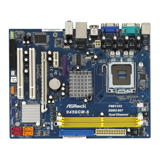
Page 2: Layout
PCI Express x1 Slot (PCIE1) Secondary SATAII Connector (SATAII_2; Red) Print Port Header (LPT1, Purple) Primary SATAII Connector (SATAII_1; Red) OC 800 Jumper Chassis Speaker Header (SPEAKER 1, Purple) 28 ATX 12V Connector (ATX12V1) 2 2 2 2 2 ASRock 945GCM-S Motherboard... - Page 3 Line Out (Lime) PS/2 Keyboard Port (Purple) * To enable Multi-Streaming function, you need to connect a front panel audio cable to the front panel audio header. Please refer to below steps for the software setting of Multi-Streaming. For Windows ®...
-
Page 4: Package Contents
This Quick Installation Guide contains introduction of the motherboard and step-by- step installation guide. More detailed information of the motherboard can be found in the user manual presented in the Support CD. Because the motherboard specifications and the BIOS software might be updated, the content of this manual will be subject to change without notice. -
Page 5: Specifications
Specifications Specifications Specifications Specifications Specifications Platform - Micro ATX Form Factor: 9.6-in x 7.5-in, 24.4 cm x 19.1 cm ® - LGA 775 for Intel Dual Core Core 2 Extreme / Core 2 Duo / Pentium ® Dual Core / Celeron ®... - Page 6 Overclocking may affect your system stability, or even cause damage to the components and devices of your system. It should be done at your own risk and expense. We are not responsible for possible damage caused by overclocking.
- Page 7 Before installing SATAII hard disk to SATAII connector, please read the “SATAII Hard Disk Setup Guide” on page 23 of “User Manual” in the support CD to adjust your SATAII hard disk drive to SATAII mode. You can also connect SATA hard disk to SATAII connector directly.
- Page 8 12. While CPU overheat is detected, the system will automatically shutdown. Before you resume the system, please check if the CPU fan on the motherboard functions properly and unplug the power cord, then plug it back again. To improve heat dissipation, remember to spray thermal grease between the CPU and the heatsink when you install the PC system.
-
Page 9: Pre-Installation Precautions
Before you insert the 775-LAND CPU into the socket, please check if the CPU surface is unclean or if there is any bent pin on the socket. Do not force to insert the CPU into the socket if above situation is found. - Page 10 775-LAND CPU For proper inserting, please ensure to match the two orientation key notches of the CPU with the two alignment keys of the socket. Step 2-3. Carefully place the CPU into the socket by using a purely vertical motion.
-
Page 11: Installation Of Cpu Fan And Heatsink
1. It is recommended to use the cap tab to handle and avoid kicking off the PnP cap. 2. This cap must be placed if returning the motherboard for after service. Step 4. Close the socket: Step 4-1. Rotate the load plate onto the IHS. -
Page 12: Installation Of Memory Modules (Dimm)
Unlock a DIMM slot by pressing the retaining clips outward. Step 2. Align a DIMM on the slot such that the notch on the DIMM matches the break on the slot. The DIMM only fits in one correct orientation. It will cause permanent damage to the motherboard and the DIMM if you force the DIMM into the slot at incorrect orientation. -
Page 13: Expansion Slots (Pci And Pci Express Slots)
2.4 Expansion Slots (PCI and PCI Express Slots) 2.4 Expansion Slots (PCI and PCI Express Slots) There are 2 PCI slots and 2 PCI Express slots on this motherboard. PCI slots: PCI slots are used to install expansion cards that have the 32-bit PCI interface. PCIE slots: PCIE1 (PCIE x1 slot) is used for PCI Express cards with x1 lane width cards, such as Gigabit LAN card, SATA2 card, etc. -
Page 14: Jumpers Setup
2-pin jumper (see p.2 No. 8) Note: CLRCMOS1 allows you to clear the data in CMOS. The data in CMOS includes system setup information such as system password, date, time, and system setup parameters. To clear and reset the system parameters to default setup, please turn off the computer and unplug the power cord from the power supply. -
Page 15: Onboard Headers And Connectors
FDD connector (33-pin FLOPPY1) (see p.2 No. 20) the red-striped side to Pin1 Note: Make sure the red-striped side of the cable is plugged into Pin1 side of the connector. Primary IDE connector (Blue) (39-pin IDE1, see p.2 No. 7) - Page 16 HDA to function correctly. Please follow the instruction in our manual and chassis manual to install your system. 2. If you use AC’97 audio panel, please install it to the front panel audio header as below: A.
- Page 17 For Windows 2000 / XP / XP 64-bit OS: Please select “Front Mic” as default record device. If you want to hear your voice through front mic, please deselect "Mute" icon in “Front Mic” of “Playback” portion. For Windows ®...
- Page 18 Though this motherboard provides 4-Pin CPU fan (Quiet Fan) support, the 3-Pin CPU fan still can work successfully even without the fan speed control function. If you plan to connect the 3-Pin CPU fan to the CPU fan connector on this motherboard, please connect it to Pin 1-3.
-
Page 19: Installation
STEP 2: Connect the SATA power cable to the SATA / SATAII hard disk. STEP 3: Connect one end of the SATA data cable to the motherboard’s SATAII connector. STEP 4: Connect the other end of the SATA data cable to the SATA / SATAII hard disk. 2.8 Driver Installation Guide... -
Page 20: Bios Information
To begin using the Support CD, insert the CD into your CD-ROM drive. It will display the Main Menu automatically if “AUTORUN” is enabled in your computer. If the Main Menu does not appear automatically, locate and double-click on the file “ASSETUP. - Page 21 Wir danken Ihnen für den Kauf des ASRock 945GCM-S Motherboard, ein zuverlässiges Produkt, welches unter den ständigen, strengen Qualitätskontrollen von ASRock gefertigt wurde. Es bietet Ihnen exzellente Leistung und robustes Design, gemäß der Verpflichtung von ASRock zu Qualität und Halbarkeit.
-
Page 22: Spezifikationen
1 . 2 Spezifikationen Spezifikationen Spezifikationen Spezifikationen Spezifikationen Plattform - Micro ATX-Formfaktor: 24.4 cm x 19.1 cm; 9.6 Zoll x 7.5 Zoll ® - LGA 775 für Intel Dual Core Core 2 Extreme- / Core Duo- / Pentium ® Dual Core- / Celeron ®... - Page 23 - 24-pin ATX-Netz-Header - 4-pin anschluss für 12V-ATX-Netzteil - Interne Audio-Anschlüsse - Anschluss für Audio auf der Gehäusevorderseite - 2 x USB 2.0 Buchse (unterstützt 4 USB 2.0 Ports) (siehe VORSICHT 9) BIOS - 4Mb AMI BIOS - AMI legal BIOS mit Unterstützung für “Plug and Play”...
- Page 24 Beachten Sie bitte, dass Overclocking, einschließlich der Einstellung im BIOS, Anwenden der Untied Overclocking-Technologie oder Verwenden von Overclocking-Werkzeugen von Dritten, mit einem gewissen Risiko behaftet ist. Overclocking kann sich nachteilig auf die Stabilität Ihres Systems auswirken oder sogar Komponenten und Geräte Ihres Systems beschädigen.
- Page 25 Shutdown durch. Bevor Sie das System neu starten, prüfen Sie bitte, ob der CPU-Lüfter am Motherboard richtig funktioniert, und stecken Sie bitte den Stromkabelstecker aus und dann wieder ein. Um die Wärmeableitung zu verbessern, bitte nicht vergessen, etwas Wärmeleitpaste zwischen CPU und Kühlkörper zu sprühen.
-
Page 26: Einstellung Der Jumper
+5VSB (Standby) zu setzen (siehe S.2 - No. 1) und die PS/2 oder USB- Weckfunktionen zu aktivieren. Hinweis: Um +5VSB nutzen zu können, muss das Netzteil auf dieser Leitung 2A oder mehr leisten können. CMOS löschen (CLRCMOS1, 2-Pin jumper) 2-Pin jumper (siehe S.2 - No. - Page 27 (33-Pin FLOPPY1) die rotgestreifte Seite auf Stift 1 (siehe S.2 - No. 20) Hinweis: Achten Sie darauf, dass die rotgestreifte Seite des Kabel mit der Stift 1- Seite des Anschlusses verbunden wird. Primärer IDE-Anschluss (Blauer) (39-pin IDE1, siehe S.2 - No. 7)
- Page 28 Interne Audio-Anschlüsse Diese ermöglichen Ihnen Stereo-Signalquellen, wie z. B. (4-Pin CD1) CD-ROM, DVD-ROM, TV-Tuner (CD1: siehe S.2 - No. 23) oder MPEG-Karten mit Ihrem System zu verbinden. Anschluss für Audio auf Dieses Interface zu einem der Gehäusevorderseite Audio-Panel auf der Vorderseite Ihres Gehäuses, ermöglicht...
- Page 29 E. Rufen Sie das BIOS-Setup-Dienstprogramm auf. Wechseln Sie zu Erweiterte Einstellungen und wählen Sie Chipset-Konfiguration. Setzen Sie die Option Frontleistenkontrolle von [Automatisch] auf [Aktiviert]. F. Rufen Sie das Windows-System auf. Klicken Sie auf das Symbol in der Taskleiste unten rechts, um den Realtek HD Audio-Manager aufzurufen. ®...
- Page 30 Obwohl dieses Motherboard einen 24-pol. ATX-Stromanschluss bietet, kann es auch mit einem modifizierten traditionellen 20-pol. ATX-Netzteil verwendet werden. Um ein 20-pol. ATX-Netzteil zu verwenden, stecken Sie den Stecker mit Pin 1 und Pin 13 ein. Installation eines 20-pol. ATX-Netzteils ASRock 945GCM-S Motherboard...
- Page 31 Erscheint der Wilkommensbildschirm nicht, so “doppelklicken” Sie bitte auf das File ASSETUP.EXE im BIN-Verzeichnis der Support-CD, um die Menüs aufzurufen. Das Setup-Programm soll es Ihnen so leicht wie möglich machen. Es ist menügesteuert, d.h. Sie können in den verschiedenen Untermenüs Ihre Auswahl treffen und die Programme werden dann automatisch installiert.
-
Page 32: Contenu Du Paquet
1.1 Contenu du paquet Carte mère ASRock 945GCM-S (Facteur de forme Micro ATX : 9.6 pouces x 7.5 pouces, 24.4 cm x 19.1 cm) Guide d’installation rapide ASRock 945GCM-S CD de soutien ASRock 945GCM-S Un câble ruban IDE Ultra ATA 66/100 80 conducteurs (en option) Un câble de données Serial ATA (SATA) (en option) - Page 33 Quad Core (voir ATTENTION 1) - Prise en charge de la technologie Hyper-Threading (voir ATTENTION 2) - Prend en charge la technologie Untied Overclocking (voir ATTENTION 3) - Prise en charge de la technologie EM64T par le CPU ® Chipsets - Northbridge: Intel 945GC ®...
- Page 34 ® ® - Microsoft Windows 2000 / XP / XP 64-bit / Vista / Vista 64-bit Certifications - FCC, CE * Pour de plus amples informations sur les produits, s’il vous plaît visitez notre site web: http://www.asrock.com ASRock 945GCM-S Motherboard...
- Page 35 ATTENTION Il est important que vous réalisiez qu’il y a un certain risque à effectuer l’overclocking, y compris ajuster les réglages du BIOS, appliquer la technologie Untied Overclocking, ou utiliser des outils de tiers pour l’overclocking. L’overclocking peut affecter la stabilité de votre système, ou même causer des dommages aux composants et dispositifs de votre...
- Page 36 Avant d’installer le disque dur SATAII au connecteur SATAII, veuillez lire le Guide « Installation du disque dur SATAII » à la page 23 du « Manuel de l’utilisateur » qui se trouve sur le CD de support pour régler votre lecteur de disque dur SATAII au mode SATAII.
- Page 37 (OC 800, cavalier à 3 broches, voir p.2 N° 27) Par défaut Note: Si vous voulez overclocker le CPU FSB800 (par ex les gammes de CPU Cel400, E1000, E2000, E4000, E5000, E6000) en FSB1066 sur cette carte mère, il vous faut régler les cavaliers. Veuillez mettre en contact les bornes 2 et 3.
- Page 38 (FLOPPY1 br. 33) (voir p.2 No. 20) le côté avec fil rouge côté Broche1 Note: Assurez-vous que le côté avec fil rouge du câble est bien branché sur le côté Broche1 du connecteur. Connecteur IDE primaire (Bleu) (IDE1 br. 39, voir p.2 No. 7)
- Page 39 En-tête USB 2.0 A côté des quatre ports USB 2.0 par défaut sur le panneau (USB6_7 br.9) E/S, il y a deux embases USB (voir p.2 No. 15) 2.0 sur cette carte mère. Chaque embase USB 2.0 peut (USB4_5 br.9) prendre en charge 2 ports USB (voir p.2 No.
- Page 40 1. L’audio à haute définition (HDA) prend en charge la détection de fiche, mais le fil de panneau sur le châssis doit prendre en charge le HDA pour fonctionner correctement. Veuillez suivre les instructions dans notre manuel et le manuel de châssis afin installer votre système.
- Page 41 (voir p.2 No. 4) ien que cette carte mère offre un support de (Ventilateur silencieux) ventilateur de CPU à 4 broches , le ventilateur de CPU à 3 broches peut bien fonctionner même sans la fonction de commande de vitesse du ventilateur.
-
Page 42: Informations Sur Le Cd De Support
BIOS après le POST, veuillez redémarrer le système en pressant <Ctl> + <Alt> + <Suppr>, ou en pressant le bouton de reset sur le boîtier du système. Vous pouvez également redémarrer en éteignant le système et en le rallumant. -
Page 43: Contenuto Della Confezione
Grazie per aver scelto una scheda madre ASRock 945GCM-S, una scheda madre affidabile prodotta secondo i severi criteri di qualità ASRock. Le prestazioni eccellenti e il design robusto si conformano all’impegno di ASRock nella ricerca della qualità e della resistenza. - Page 44 1.2 Specifiche Specifiche Specifiche Specifiche Specifiche Piattaforma - Micro ATX Form Factor: 9.6-in x 7.5-in, 24.4 cm x 19.1 cm Processore - LGA 775 per Intel ® Dual Core Core 2 Extreme / Core 2 Duo / ® ® Pentium...
- Page 45 Connettori - 4 x connettori SATAII 3.0Go/s (Non supporta le funzioni “RAID” e “Collegamento a caldo”) (vedi ATTENZIONE 8) - 1 x connettori ATA100 IDE (supporta fino a 2 dispositivi IDE) - 1 x porta Floppy - 1 x Collettore porta stampante...
- Page 46 AVVISO Si prega di prendere atto che la procedura di overclocking implica dei rischi, come anche la regolazione delle impostazioni del BIOS, l’applicazione della tecnologia Untied Overclocking Technology, oppure l’uso di strumenti di overclocking forniti da terzi. L’overclocking può influenzare la stabilità del sistema, ed anche provocare danni ai componenti ed alle periferiche del sistema.
- Page 47 64-bit / Vista / XP 64 bit / XP SP1; SP2/2000 SP4. 10. Dotato di un design avanzato e brevettato dell’hardware e del software, Intelligent Energy Saver è una tecnologia rivoluzionaria che offre un risparmio energetico senza pari. In altre parole: è capace di fornire un risparmio energetico eccezionale e di migliorare l’efficienza senza...
- Page 48 Nota: CLRCMOS1 consente di pulire i dati nella CMOS. I dati nella CMOS includono informazioni del setup del sistema, come per esempio la password di sistema, la data, l’ora, e i parametri del setup di sistema. Per pulire I parametri di sistema e resettare ai parametri di default, spegnere il computer e scollegare l’alimentatore, poi collegare il jumper sul CLRCMOS1 per 5 secondi.
- Page 49 (33-pin FLOPPY1) (vedi p.2 Nr. 20) Lato del Pin1 con la striscia rossa Nota: Assicurarsi che il lato del cavo con la striscia rossa sia inserito nel lato Pin1 del connettore. Connettore IDE primario (Blu) (39-pin IDE1, vedi p.2 Nr. 7)
- Page 50 Connettere al gruppo alimentazione SATA al di alimentazione connettore power dell’alimentatore. Collettore USB 2.0 Oltre alle quattro porte USB 2.0 predefinite nel pannello I/O, la (9-pin USB6_7) scheda madre dispone di due (vedi p.2 No. 15) intestazioni USB 2.0. Ciascuna intestazione USB 2.0 supporta...
- Page 51 1. La caratteristica HDA (High Definition Audio) supporta il rilevamento dei connettori, però il pannello dei cavi sul telaio deve supportare la funzione HDA (High Definition Audio) per far sì che questa operi in modo corretto. Attenersi alle istruzioni del nostro manuale e del manuale del telaio per installare il sistema.
- Page 52 Sebbene la presente scheda madre disponga di un supporto per ventola CPU a 4 piedini (ventola silenziosa), la ventola CPU a 3 piedini è in grado di funzionare anche senza la funzione di controllo della velocità della ventola. Se si intende collegare la ventola CPU a 3 piedini al connettore della ventola CPU su questa scheda madre, collegarla ai piedini 1-3.
- Page 53 BIOS; altrimenti, POST continua con i suoi test di routine. Per entrare il BIOS Setup dopo il POST, riavvia il sistema premendo <Ctl> + <Alt> + <Delete>, o premi il tasto di reset sullo chassis del sistema. Per informazioni più dettagliate circa il Setup del BIOS, fare riferimento al Manuale dell’Utente (PDF file) contenuto nel cd di...
-
Page 54: Contenido De La Caja
ASRock. Esta Guía rápida de instalación contiene una introducción a la placa base y una guía de instalación paso a paso. Puede encontrar una información más detallada sobre la placa base en el manual de usuario incluido en el CD de soporte. - Page 55 1.2 Especificación Especificación Especificación Especificación Especificación Plataforma - Factor forma Micro ATX: 24,4 cm x 19,1 cm, 9,6” x 7,5” ® Procesador - LGA 775 para Intel Dual Core Core 2 Extreme / Core 2 Duo ® ® / Pentium...
- Page 56 - En conformidad con Microsoft Windows 2000 / XP / XP 64 bits / Vista / Vista 64 bits Certificaciones - FCC, CE * Para más información sobre los productos, por favor visite nuestro sitio web: http://www.asrock.com ASRock 945GCM-S Motherboard...
- Page 57 ADVERTENCIA Tenga en cuenta que hay un cierto riesgo implícito en las operaciones de aumento de la velocidad del reloj, incluido el ajuste del BIOS, aplicando la tecnología de aumento de velocidad liberada o utilizando las herramientas de aumento de velocidad de otros fabricantes.
- Page 58 10. Contiene avanzado hardware y diseño de software de propietario. Intelligent Energy Saver es una revolucionaria tecnología que consigue ahorros de energía sin rival. En otras palabras, permite alcanzar un nivel de ahorro de energía excepcional y mejorar la eficiencia energética sin sacrificar el rendimiento del procesador.
- Page 59 3 para habilitar +5VSB (vea p.2, N. 1) (standby) para PS/2 o USB wake up events. Atención: Para elegir +5VSB, se necesita corriente mas que 2 Amp proveida por la fuente de electricidad. Limpiar CMOS (CLRCMOS1, jumper de 2 pins) jumper de 2 pins (vea p.2, N.
- Page 60 (vea p.2, N. 20) la banda roja debe quedar en el mismo lado que el contacto 1 Atención: Asegúrese que la banda roja del cable queda situado en el mismo lado que el contacto 1 de la conexión. IDE conector primario (Azul) (39-pin IDE1, vea p.2, N.
- Page 61 Cable de alimentación Conecte el extremo negro del de serie ATA (SATA) cable de alimentación SATA en la conexión de alimentación (Opcional) de cada unidad. A continuación, Conectar a la conexión de conecte el extremo blanco del alimentación del disco...
- Page 62 2. Si utiliza el panel de sonido AC’97, instálelo en la cabecera de sonido del panel frontal de la siguiente manera: A. Conecte Mic_IN (MIC) a MIC2_L.
- Page 63 Si pretende enchufar el ventilador de procesador de 3 contactos en el conector del ventilador de procesador de esta placa base, conéctelo al contacto 1-3. Contacto 1-3 conectado Instalación del ventilador de 3 contactos...
- Page 64 Para iniciar la instalación, ponga el CD en el lector de CD y se desplegará el Menú Principal automáticamente si «AUTORUN» está habilitado en su computadora. Si el Menú...
- Page 65 Gratos por comprar nossa placa–mãe 945GCM-S, um produto confiável feito com ASRock um estrito controle de qualidade consistente. Com um excelente desempenho, essa placa é dotada de um projeto robusto que atende a ASRock de compromisso com a qualidade e durabilidade.
- Page 66 1.2 Especificações 1.2 Especificações 1.2 Especificações 1.2 Especificações 1.2 Especificações Plataforma - Formato Micro ATX: 9,6 pol. x 7,5 pol., 24,4 cm x 19,1 cm ® - Socket Intel Dual Core Core 2 Extreme / Core 2 Duo / ®...
- Page 67 - Medição de temperatura da placa-mãe - Tacômetros de ventilador do Processador - Tacômetros de ventilador do chassis - Ventoinha silenciosa para a CPU - Monitoramento de voltagem : +12 V, +5 V, +3.3 V, Vcore Sistema - Microsoft ®...
- Page 68 AVISO Tenha em atenção que a operação de overclocking envolve alguns riscos, nomeadamente no que diz respeito ao ajuste das definições do BIOS, à aplicação da tecnologia Untied Overclocking ou à utilização de ferramentas de overclocking de terceiros. O overclocking pode afectar a estabilidade do seu sistema ou até...
- Page 69 CPU podem provocar instabilidade do sistema ou danos à CPU. 12. Assim que se detecta um superaquecimento na CPU, o sistema se desliga automaticamente e o botão de energia do chassis fica inativo. Cheque o ventilador da CPU na placa–mãe, para verificar se está...
- Page 70 (veja a folha 2, No. 1) para PS/2 ou eventos de wake up na USB. Nota: Para escolher +5VSB, é preciso uma corrente de stand by de 2 A ou mais. Restaurar CMOS (CLRCMOS1, jumper de 2 pinos) jumper de 2 pinos (veja a folha 2, No.
- Page 71 (FLOPPY 1, 33 pinos) (veja a folha 2, No. 20) o lado com listras vermelhas para o Pino 1 Nota: Certifique-se de que o lado com listras vermelhas no cabo seja conectado ao lado Pino 1 do conector. Conector primário (Azul) (IDE1 de 39 pinos, veja a folha 2, No.
- Page 72 Estes conectores permitem que se receba entrada de (CD1 de 4 pinos) áudio em estéreo de fontes (CD1: veja a floha 2, No. 23) de áudio como CD-ROM, DVD-ROM, placa sintonizadora de TV ou placa MPEG. Conector Áudio do painel Esta é...
- Page 73 Siga s instruções que aparecem no manual e no manual do chassis para instalar o sistema. 2. Se utilizar o painel de áudio AC’97, instale-o no cabeçalho de áudio do painel frontal, como a figura abaixo mostra: A. Ligue o Mic_IN (MIC) ao MIC2_L.
- Page 74 (Ventoinha silenciosa), uma ventoinha de 3 pinos para CPU poderá funcionar mesmo sem a função de controlo de velocidade da ventoinha. Se pretender ligar uma ventoinha de 3 pinos para CPU ao conector de ventoinha do CPU nesta placa-mãe, por favor, ligue-a aos pinos 1-3.
- Page 75 Mãe contem: drivers e utilitários necessários para um melhor desempenho da placa Mãe. Para começar a usar o CD de instalação, introduza o CD na leitora de CD-ROM do computador. Automaticamente iniciará o menu principal, casa o AUTORUN esteja ativado.
- Page 76 ASRock 945GCM-S Motherboard...
- Page 77 ® ® ® ® ® ® ® ASRock 945GCM-S Motherboard...
- Page 78 ® ASRock 945GCM-S Motherboard...
- Page 79 “ ” ® ® ® ® ® “ ” “ ” ASRock 945GCM-S Motherboard...
- Page 80 ASRock 945GCM-S Motherboard...
- Page 81 “ ” “ ” “ ” “ ” ASRock 945GCM-S Motherboard...
- Page 82 ASRock 945GCM-S Motherboard...
- Page 83 ASRock 945GCM-S Motherboard...
- Page 84 ® ® ® ® “ ” “ ” “ ” “ ” ® “ ” “ ” ASRock 945GCM-S Motherboard...
- Page 85 ASRock 945GCM-S Motherboard...
- Page 86 “ ” “ ” ASRock 945GCM-S Motherboard...