Advertisement
Quick Links
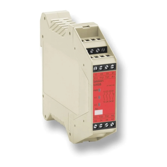
Safety Relay Unit
G9SB
Ultra Slim Safety
Relay Unit
• Models of width 17.5 mm available with
2 or 3 safety contacts. Models of width
22.5 mm with 3 safety contacts and
auxiliary contact are also available.
• Conforms to EN standards.
(TÜV approval)
• DIN track mounting possible.
• Slim size controller dedicated for safey
sensors F3SN, F3SH, F3S-B, F3S-
TGR, F3SL, F3S-J
Ordering Information
Auxiliary
Main contacts
contact
DPST-NO
2 safety
None
contacts
3PST-NO
3 safety
SPST-NC
contacts
Model Number Legend
G9SB-##### #
1 2 3 4 5
6
1. Function
None: Emergency stop
2. Contact Configuration (Safety Output)
2:
DPST-NO
3:
3PST-NO
3. Contact Configuration (OFF-delay Output)
0:
None
4. Contact Configuration (Auxiliary Output)
0:
None
1:
SPST-NC
G9SB
Number of input
Reset mode
channels
2 channels
Auto-reset
1 channel or
2 channels
2 channels
Manual-reset
1 channel or
2 channels
None
(direct breaking)
2 channels
Auto-reset
1 channel or
2 channels
2 channels
Manual-reset
1 channel or
2 channels
Rated
Input type
voltage
Inverse
G9SB-2002-A
+ common
G9SB-200-B
24 VAC/VDC
Inverse
G9SB-2002-C
+ common
G9SB-200-D
---
24 VDC
G9SB-3010
Inverse
G9SB-3012-A
+ common
G9SB-301-B
24 VAC/VDC
Inverse
G9SB-3012-C
+ common
G9SB-301-D
5. Input Configuration
None: 1-channel or 2-channel input possible
0:
None (direct breaking)
2:
2-channel input
6. Miscellaneous
A:
Auto-reset, inverse input
B:
Auto-reset, + common input
C:
Manual-reset, inverse input
D:
Manual-reset, + common input
Category
Model
(EN954-1)
4
17.5 mm
3
17.5 mm
4
22.5 mm
Size
G-123
Advertisement

Related Manuals for Omron G9SB


Summary of Contents for Omron G9SB
- Page 1 Safety Relay Unit G9SB Ultra Slim Safety Relay Unit • Models of width 17.5 mm available with 2 or 3 safety contacts. Models of width 22.5 mm with 3 safety contacts and auxiliary contact are also available. • Conforms to EN standards.
-
Page 2: Specifications
2. The bounce time is not included in the figure for operating time. 3. The response time is the time it takes for the main contact to open after the input is turned OFF. 4. The insulation resistance was measured with 500 VDC at the same places that the dielectric strength was checked. -
Page 3: Application Examples
See note. and 41-42. KM1 KM2 Note: 1. External connections and timing charts for G9SB-200-B/301-B models are the same as those for G9SB-2002-A/3012-A models. 2. This circuit conforms to EN954-1 Safety Category 4. G9SB-2002-C (24 VAC/VDC) or G9SB-3012-C (24 VAC/VDC) - Page 4 G9SB-200-D (24 VAC/VDC) or G9SB-301-D (24 VAC/VDC) with 2-channel Safety Area Sensor/Manual-reset Emitter Receiver F3SN-A F3SH-A RS-485(A) (Gray) Timing Chart RS-485(B) (Pink) F3SN-A: Incident Interrupted Reset switch S1 K1 and K2 (NC) K1 and K2 (NO) KM1 and KM2 (NC)
- Page 5 KM1 and KM2 (NO) Open Safety limit switch with direct opening mechanism (D4D or D4B) Limit switch KM1 and KM2: Magnetic Contactor Control 3-phase motor circuit 34 42 KM1 KM2 Note: This circuit conforms to EN954-1 Safety Category 3. G9SB G-127...
- Page 6 (green) (orange) (orange) (orange) (orange) T21 T22 A2 42 T32 A2 14 24 T32 14 24 34 2 ¥ 5 = 10 112 max. 100 max. 18 max. (Average: 17.5) G9SB-301-# Terminal Arrangement G9SB-200#-# 13 23 33 3 ¥ 5 = 15 T11 T12 T31 112 max.
-
Page 7: Installation
G9SB-3010 (24 VDC) Control circuit 34 42 Note: 1. For 1-channel input with G9SB-###-B/D models, short terminals T12 and T22. It is not possible to wire G9SB-###2-A/C models for 1-channel input. 2. Only G9SB-301#-# models have terminals 33-34 and 41-42. G9SB... - Page 8 ALL DIMENSIONS SHOWN ARE IN MILLIMETERS. To convert millimeters into inches, multiply by 0.03937. To convert grams into ounces, multiply by 0.03527. Cat. No. J130-E2-01-X In the interest of product improvement, specifications are subject to change without notice.