
Related Manuals for Daikin FXKA20AMVEB


Summary of Contents for Daikin FXKA20AMVEB
- Page 1 Installation and operation manual VRV system air conditioner FXKA20AMVEB FXKA25AMVEB FXKA32AMVEB FXKA40AMVEB Installation and operation manual FXKA50AMVEB English VRV system air conditioner FXKA63AMVEB...
- Page 2 4P686644-14D...
- Page 3 4P686644-16D...
-
Page 4: Table Of Contents
Daikin website (publicly accessible). 14.1 Specifications of standard wiring components ......18 ▪ The full set of the latest technical data is available on the Daikin 14.2 To connect the electrical wiring to the indoor unit ..... 19 Business Portal (authentication required). -
Page 5: Specific Installer Safety Instructions
Make sure installation, servicing, maintenance, repair and applied materials follow the instructions from Daikin WARNING (including all documents listed in “Documentation set”) and, in addition, comply with applicable legislation and are ▪ If the power supply has a missing or wrong N-phase, performed by qualified persons only. -
Page 6: Instructions For Equipment Using R32 Refrigerant
0,25 times the maximum allowable pressure. No leak shall Make sure installation, servicing, maintenance and repair be detected. comply with instructions from Daikin and with applicable legislation (for example national gas regulation) and are executed ONLY by authorised persons. 2.1.1... -
Page 7: Instructions For Safe Operation
3 User safety instructions WARNING ▪ In case of accidental refrigerant leaks, make sure there are no naked To prevent electrical shocks or fire: flames. The refrigerant itself is ▪ Do NOT rinse the unit. entirely safe, non-toxic and mildly ▪... - Page 8 3 User safety instructions CAUTION CAUTION Do NOT operate the system when Do NOT insert fingers, rods or other using a room fumigation-type objects into the air inlet or outlet. When insecticide. Chemicals could collect in the fan is rotating at high speed, it will the unit, and endanger the health of cause injury.
-
Page 9: About The System
4 About the system WARNING WARNING Do NOT let the indoor unit get wet. The R32 refrigerant leakage sensor Possible consequence: Electrical must be replaced after every detection shock or fire. or at the end of its lifetime. ONLY authorised persons may replace the refrigerant" [ 4 12]) About the refrigerant (see "7.3 About the... -
Page 10: System Layout
5 User interface System layout About operation modes INFORMATION INFORMATION The following figure is an example and may NOT Depending on the installed system, some operation modes completely match your system layout will not be available. e f g h ▪... -
Page 11: To Operate The System
7 Maintenance and service Automatic airflow control What. The system directs the airflow differently, depending on the user selection. Cooling Heating CAUTION ▪ When the room temperature is ▪ When starting operation. lower than controller's ▪ When the room temperature is ALWAYS use the user interface to adjust the position of setpoint for cooling operation higher than the controller's... -
Page 12: Cleaning The Unit Exterior And Air Filter
7 Maintenance and service NOTICE When cleaning the heat exchanger, make sure to remove the electronic components above it. Water or detergent might deteriorate the insulation of electronic components and result in burnout of these components. DANGER: RISK OF ELECTROCUTION Disconnect the power supply for more than 10 ... -
Page 13: About The Refrigerant Leakage Sensor
In case of detection when the unit is operating www.daikin.eu for more troubleshooting tips. Use the 1 The user interface displays error "A0-11" and emits an alarm search function to find your model. sound. The status indicator blinks. -
Page 14: Relocation
9 Relocation Relocation Disposal Contact your dealer to remove and reinstall the entire unit. Moving NOTICE units requires technical expertise. Do NOT try to dismantle the system yourself: dismantling of the system, treatment of the refrigerant, oil and other parts MUST comply with applicable legislation. Units MUST be treated at a specialised treatment facility for reuse, recycling and recovery. -
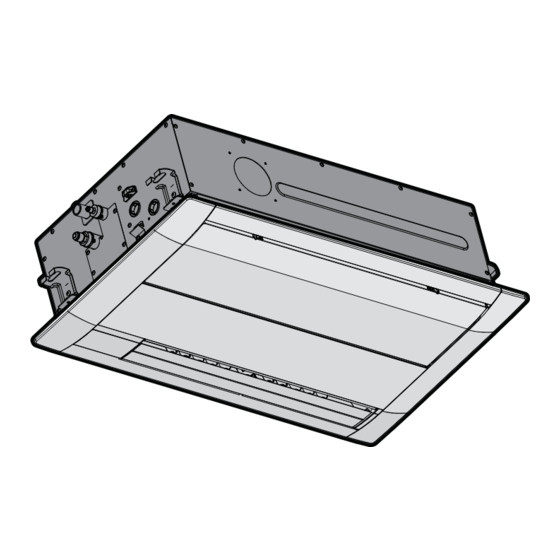
Page 15: Mounting The Indoor Unit
12 Unit installation setting" [ 4 20]. Maximum: 3.5 m. See "16.1 Field Top nut (field supply) Air outlet Bottom double nut (field supply) Air inlet Washer for hanger bracket (accessory) Indoor unit Hanger bracket (attached to the unit) Floor Decoration panel dimensions Ceiling opening dimensions INFORMATION Indoor unit dimensions... -
Page 16: Guidelines When Installing The Drain Piping
12 Unit installation ▪ Combining drain pipes. You can combine drain pipes. Make sure to use drain pipes and T-joints with the correct gauge for the operating capacity of the units. Level (mm) NOTICE Do NOT install the unit tilted. Possible consequence: If T-joint the unit is tilted against the direction of the condensate flow To connect the drain piping to the indoor unit... -
Page 17: Piping Installation
13 Piping installation Metal clamp (accessory) Large sealing pad (accessory) Drain piping (field supply) Drain outlet for maintenance Pull out the plug. ▪ Do NOT wiggle the plug up and down. Push in the plug. ▪ Set the plug and push it in using a Phillips screwdriver. Plastic water container with tube length ≥100 mm Drain pump and float switch location Service drain outlet (with rubber plug). -
Page 18: Refrigerant Piping Insulation
14 Electrical installation ▪ Insulation. Insulate the refrigerant piping on the indoor unit as Class Pipe outer diameter (mm) follows: Liquid piping Gas piping 20~32 Ø6.4 mm Ø9.5 mm 40~63 Ø6.4 mm Ø12.7 mm Refrigerant piping material ▪ Piping material: phosphoric acid deoxidised seamless copper ▪... -
Page 19: To Connect The Electrical Wiring To The Indoor Unit
14 Electrical installation MCA=Minimum circuit ampacity. Stated values are maximum 3 Transmission cable: Route the cable through the frame and values (see electrical data of indoor unit for exact values). connect it to the terminal block (make sure the symbols F1 and F2 match with the symbols on the outdoor unit). -
Page 20: Commissioning
Next commissioning instructions in this chapter, a general Configuration commissioning checklist is also available on the Daikin Business Portal (authentication required). The general commissioning checklist is complementary to 16.1 Field setting the instructions in this chapter and can be used as a... - Page 21 16 Configuration Setting: Thermostat differential changeover (if remote sensor is If the distance to the floor is (m) Then used) — If the system contains a remote sensor, set the increase/decrease ≤2.7 13 (23) increments. 2.7<x≤3.0 If you want to change increments to… Then 3.0<x≤3.5 —...
-
Page 22: Technical Data
▪ A subset of the latest technical data is available on the regional Connector (frame ground) Daikin website (publicly accessible). Harness ▪ The full set of the latest technical data is available on the Daikin Business Portal (authentication required). H*P, LED*, V*L Pilot lamp, light emitting diode Light emitting diode (service 17.1... - Page 23 17 Technical data Symbol Meaning Stepper motor Compressor motor Fan motor Drain pump motor Swing motor MR*, MRCW*, MRM*, MRN* Magnetic relay Neutral n=*, N=* Number of passes through ferrite core Pulse-amplitude modulation PCB* Printed circuit board Power module Switching power supply PTC* PTC thermistor Insulated gate bipolar transistor...
- Page 24 3P747532-2A 2023.11...