Table of Contents
Advertisement
Available languages
Available languages
Quick Links
en
PORTABLE AIR CONDITIONER
USER MANUAL
MODEL NUMBER
MAP05R1AWWT
MAP05R1AWWT-T
Before using this product, please read this manual carefully and keep it for future reference.
The design and specifications are subject to change without prior notice for product improvement. Consult
with your dealer or the manufacturer for details.
Advertisement
Table of Contents

Related Manuals for Midea MAP05R1AWWT


Summary of Contents for Midea MAP05R1AWWT
- Page 1 PORTABLE AIR CONDITIONER USER MANUAL MODEL NUMBER MAP05R1AWWT MAP05R1AWWT-T Before using this product, please read this manual carefully and keep it for future reference. The design and specifications are subject to change without prior notice for product improvement. Consult with your dealer or the manufacturer for details.
-
Page 2: Read This Manual
THANK YOU LETTER Thank you for choosing Midea! Before using your new Midea product, please read this manual thoroughly to ensure that you know how to operate the OWNER’S MANUAL Safety Precautions Before you get start product overview Installation overview... -
Page 3: Safety Precautions
Safety Precautions Must read the warning message. Read Safety Precautions Before Operation and Installation To prevent death or injury to the user or other people and property damage, the following instructions must be followed. Incorrect operation due to ignoring of instructions may cause death, harm or damage. Explanation of Symbols WARNING This symbol indicates the possibility of personnel injury or loss of life. - Page 4 WARNING Installation must be performed according to the installation instructions. Improper installation can cause water leakage, electrical shock, or fire. Use only the included accessories and parts, and specified tools for the installation. Using nonstandard parts can cause water leakage, electrical shock, fire, and injury or property damage.
- Page 5 CAUTION This appliance is not intended for use by persons (including childr ) with reduced physical, sensory or mental capabilities or lack of experience and knowledge, unless they have been given supervision or instruction concerning use of the appliance by a person responsible for their safety.
- Page 6 IMPORTANT NOTE: Read this manual CAUTION: carefully before installing or operating Risk of fire your new appliance unit. Make sure flammable materials to save this manual for future reference. Explanation of symbols displayed on the unit CAUTION This symbol shows that the operation manual should be read carefully. This symbol shows that a service personnel should be handling this equipment with CAUTION reference to the installation manual.
- Page 7 Flammable Refrigerant R32 is used within appliance. - When maintaining or disposing the appliance, the refrigerant (R32) shall be recovered properly, shall not discharge to air directly. - Compliance with national gas regulations shall be observed. - Keep ventilation openings clear of obstruction. - The appliance shall be stored so as to prevent mechanical damage from occurring.
- Page 8 1.Transport of equipment containing flammable refrigerants See transport regulations. 2.Marking of equipment using signs See local regulations. 3.Disposal of equipment using flammable refrigerants See national regulations. 4.Storage of equipment/appliances The storage of equipment should be in accordance with the manufacturer's instructions.
- Page 9 6)No ignition sources No person carrying out work in relation to a refrigerating system which involves exposing any pipe work that contains or has contained flammable refrigerant shall use any sources of ignition in such a manner that it may lead to the risk of fire or explosion.
- Page 10 7.Repairs to sealed components 1)During repairs to sealed components, all electrical supplies shall be disconnected from the equipment being worked upon prior to any removal of sealed covers, etc. If it is absolutely necessary to have an electrical supply to equipment during servicing, then a permanently operating form of leak detection shall be located at the most critical point to warn of a potentially hazardous situation.
- Page 11 (Detection equipment shall be calibrated in a refrigerant-free area). Ensure that the detector is not a potential source of ignition and is suitable for the refrigerant used. Leak detection equipment shall be set at a percentage of the LFL of the refrigerant and shall be calibrated to the refrigerant employed and the appropriate percentage of gas (25 % maximum) is confirmed.
- Page 12 an appropriate position according to the instructions. Ensure that the refrigera- tion system is earthed prior to charging the system with refrigerant. Label the system when charging is complete (if not already). Extreme care shall be taken not to overfill the refrigeration system. Prior to recharging the system it shall be pressure tested with OFN.
- Page 13 15.Recovery When removing refrigerant from a system, either for servicing or decommission- ing, it is recommended good practice that all refrigerants are removed safely. When transferring refrigerant into cylinders, ensure that only appropriate refriger- ant recovery cylinders are employed. Ensure that the correct number of cylinders for holding the total system charge is available.
- Page 14 Before you get start Preparations before installation The installation must be Installing your AC n u a carried out in strict should take about accordance with the 30 minutes. instructions in this manual. We recommend We’re here if you need us, doing this with please contact your local a helper.
- Page 15 How to purchasing a mobile type air conditioner. will not remove enough humidity, leaving the air feeling damp. To find the proper air conditioner, determine the square footage of the room you want to cool by multiplying the room length by its width. You also need to know the air conditioner's BTU (British Thermal Unit) rating, which indicates the amount of heat it can remove from a room.
- Page 16 PRODUCT INSTALLATION LOCATION Your installation location should meet the following requirements: -Make sure that you install your unit on an even surface to minimize noise and vibration. -The unit must be installed near a grounded plug, and the Collection Tray Drain (found on the back of the unit) must be accessible.
-
Page 17: Product Overview
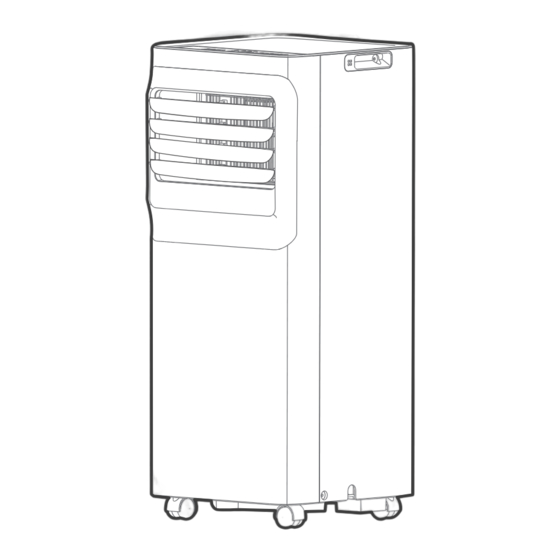
Product overview NOTE ON ILLUSTRATIONS: The unit can be controlled by the unit control panel alone or with the remote controller. Control panel Handle Remote signal receptor (both sides) Curved air outlet Air filter louver control upper air intake lever-manual adjustment (On some models) Drain outlet Air outlet... -
Page 18: Installation Overview
Installation overview Installation Completion Display Sliding Window Installation Hung Window Installation window slider assembly Extended Exhaust Hose Local Air Conditioner Security Bracket and 2 Screws NOTE Illustrations in this manual are for explanatory purposes. The actual shape of your indoor unit may be shall prevail. -
Page 19: Installation Accessories
List of installation tools (not included) Screwdriver & wrench Pencil A tape measure Scissors or Knife Saw (On some models, to shorten window adaptor for narrow windows) Installation accessories NOTE Items with (*) are on some models. Slight variations in design may occur. North America Unit Adaptor (1pc) Air exhaust passage(1pc*) - Page 20 Confirm your window type (window type and opening size Sliding Window Installation Hung Window Installation For optimal performance in operation INCORRECT CORRECT NOTE: To ensure proper function, DO NOT overextend or bend the hose. Make sure that there is no obstacle around the air outlet of the exhaust hose (in the range of 500mm) in order to the exhaust system works properly.
- Page 21 Exhaust hose and adaptors installation Exhaust hose assembly Exhaust hose Air exhaust Unit adaptor passage The Exhaust Hose assembly installation (window type) Press the exhaust hose(or extended exhaust hose) into the window slider adaptor and unit adaptor, clamp automatically by elastic buckles of the adaptors. NOTE: Please install the exhaust hose assembly according to the fittings in your kit.
- Page 22 Connect the adaptor to the unit and the window Before assembly Window Sliders After assembly Bolt 1+2: Bolt Bolt 1+2+3: Bolt Bolt Bolt 1+2+3+4: Bolt 1+4: Preparing the Adjustable Window Slider Choose the window sliders according the size of your window. Sometimes, it needs to be cut short to meet the window size, please take extra care to cut it properly.
- Page 23 Foam seal A Foam seal B (Adhesive type) (Adhesive type-shorter) Hung Window Installation Foam seal A Foam seal B (Adhesive type) (Adhesive type-shorter) Sliding Window Installation Complete sealing of window Cut the adhesive foam seal A and B strips to the proper lengths, and attach them to the window sash and frame as shown.
- Page 24 Hung Window Installation Step 1: Step 2: Insert the window slider Cut the non-adhesive foam seal C strip to match the width of assembly into the window the window. Insert the seal between the glass and the window opening. frame to prevent air and insects from getting into the room. Step 3: If desired, install the security bracket with 2 screws as shown.
-
Page 25: Sliding Window Installation
Sliding Window Installation Step 1: Step 2: Insert the window Cut the non-adhesive foam seal C strip to match the height of the slider assembly into window. Insert the seal between the glass and the window frame to the window opening. prevent air and insects from getting into the room. - Page 26 Install the Exhaust hose assembly to the unit Push the Exhaust hose into the airoutlet opening of the unit along the arrow direction. Hung Window Installation Sliding Window Installation Connect the adaptor to the unit and the window Insert the window slider adaptor into the hole of the window slider.
- Page 27 Get to know your AC Electronic control operating instructions EH0b-Display panel communication error. 1. POWER button EC-Refrigerant leakage detection malfunction(on some models). Shows protection code: 2. MODE function P1-Bottom tray is full--Connect the drain Selects the appropriate operating hose and drain the collected water away. mode.
- Page 28 9. Continuous Fan function the fan will stop when the compressor stops. 10. Other features COMFORT SENSE feature (On some models) This feature can be activated from the remote control ONLY. There is no indicator light on the control panel. The remote control serves as a remote thermostat allowing for the precise temperature control at its location.
- Page 29 Drainage guide Dehumidifying Mode Drainage Guide Step 1: Remove the Step 2: drain plug Install the continuous drain hose During dehumidifying modes, remove the drain plug from the back of the unit, install the drain connector (5/8" universal female mender) with 3/4"...
-
Page 30: Cleaning And Maintenance
Cleaning & maintenance How to clean & maintenance your AC. Air Filter & Cabinet Cleaning Clean the unit using a damp, lint-free cloth and mild detergent. Dry the unit with a dry, lint-free cloth. Maintenance Tips · Be sure to clean the air filter every 2 weeks for optimal performance. ·... - Page 31 Store the unit when not in use Step 2 Step 3 Step 1 hours *Drain the unit‘s water collection *Please refer to the actual tray then reinstall the bottom plug, and the legend is for drain plug back in. reference only. Step6 Step4 Step 5...
-
Page 32: Troubleshooting
TROUBLESHOOTING Problem Solving Common Issues The following problems are not a malfunction and in most situations will not require repairs. Problem Possible Causes Solution P1 Protection Code Collection Tray and restart the unit. Unit does not turn on when pressing In COOL mode: room ON/OFF button temperature is lower than... -
Page 33: Remote Controller Specifications
REMOTE CONTROL AND APP INSTRUCTIONS Handling the Remote Control Location of the remote control Use the remote controller within a distance of 26.2 ft (8 meters) from the air conditioner, pointing it towards the receiver. Reception is confirmed by a beep. CAUTION The air conditioner will not operate if curtains, •... -
Page 34: Function Buttons
Function Buttons TEMP DOWN Button TEMP UP Button Press this button to Press this button to decrease the indoor increase the indoor temperature setting. temperature setting. SPEED Button Used to select the desired fan speed. TIMER Button Press this button to ON/OFF Button activate the “Auto Operation starts when... - Page 35 Remote Screen Indicators Information are displayed when the remote controller is power up. Mode display COOL AUTO AUTO COOL HIGH Displayed when data transmitted. Appears when the remote is enabled and can send a signal to the unit. If remote away from the unit and press the ON/OFF button.
- Page 36 How to Use the Buttons TIMER OPERATION Press the TIMER button to initiate the Auto-start and Auto-stop setting program of the unit. To set the Auto-start/stop time. Press the TIMER button, when the TIMER ON indicator is displayed on the LED window of the air conditioner, it indicates the Auto Start setting program is initiated.
- Page 37 COMBINED TIMER (Setting both ON and OFF timers simultaneously) AUTO STOP >AUTO START (On > Stop > Start operation) This feature is useful when you want to stop the air conditioner after you go to bed, and start it again in the morning when you wake up or when you return home.
-
Page 38: Battery Warning
300 Kimball Dr Parsippany NJ 07054 Telephone number or internet contact information: Midea.com/us FCC Compliance Statement ( products subject to Part 15) This device complies with Part 15 of the FCC Rules. Operation is subject to the following two conditions: (1) This device may not cause harmful interference, and (2) this device must accept any interference received, including interference that may cause undesired operation. -
Page 39: Warranty
Operating Instructions. 2) Damages caused by services performed by persons other than authorized Midea costumer service; or external causes such as abuse, misuse, inadequate power supply or acts of God. -
Page 40: Return Policy
RETURN POLICY Return policy save your Questions about installing or operating your Midea product? receipt If you still need assistance, please call Customer Service at 1-866-646-4332. Have your sales receipt, serial number and product model mumber available when you call. - Page 42 The design and specifications are subject to change without prior notice for product improvement. Consult with the sales agency ormanufacturer for details. Any updates to the manual will be uploaded to the service website, please check for the latest version. 2023 MAPS...
- Page 43 AIRE ACONDICIONADO PORTÁTIL MANUAL DEL USUARIO NÚMERO DE MODELO MAP05R1AWWT MAP05R1AWWT-T Avisos de advertencia: antes de usar este producto, lea atentamente este manual y consérvelo para futuras referencias. El diseño y las especificaciones están sujetos a cambios sin previo aviso para la mejora del producto.
- Page 44 CARTA DE AGRADECIMIENTO ¡Gracias por elegir Midea! Antes de usar su nuevo producto Midea, lea este manual detenidamente para asegurarse de que conoce cómo operar las características y funciones que su nuevo electrodoméstico ofrece de manera segura. MANUAL DEL PROPIETARIO Precauciones de seguridad .....................
-
Page 45: Precauciones De Seguridad
Precauciones de seguridad Lea el mensaje de advertencia. Lea las precauciones de seguridad antes del funcionamiento y la instalación de la unidad Para evitar la muerte o lesiones al usuario o a otras personas, así como daños materiales, deben seguirse las siguientes instrucciones. El funcionamiento incorrecto debido a ignorar las instrucciones puede causar la muerte, lesiones o daños. - Page 46 ADVERTENCIA • La instalación debe realizarse de acuerdo con las instrucciones de instalación. Una instalación incorrecta puede causar fugas de agua, descargas eléctricas o incendios. • Utilice sólo los accesorios y piezas incluidos y las herramientas especificadas para la instalación. El uso de piezas no estándar puede provocar fugas de agua, descargas eléctricas, incendios y lesiones o daños materiales.
- Page 47 PRECAUCIÓN • Este aparato puede ser utilizado por personas (incluyendo niños) con capacidades físicas, sensoriales o mentales reducidas, o falta de experiencia y conocimientos, siempre y cuando sean supervisados o hayan recibido instrucciones sobre el uso del aparato por parte de una persona responsable de su seguridad. Los niños deben supervisarse para asegurarse de que no jueguen con el aparato.
- Page 48 NOTA IMPORTANTE: Lea atentamente PRECAUCIÓN: este manualantes de instalar o poner Riesgo de incendio en funcionamiento su nuevo aparato. materiales Asegúrese de guardar este manual para inflamables referencia futura. Explicación de los símbolos que aparecen en la unidad Este símbolo indica que debe leerse atentamente el manual de PRECAUCIÓN instrucciones.
- Page 49 Inflamable El aparato utiliza refrigerante R32. - Cuando realice el mantenimiento o deseche el aparato, el refrigerante (R32) deberá recuperarse adecuadamente y no deberá verterse directamente al aire. - Deberá respetarse la normativa nacional sobre gases. - Mantenga las aberturas de ventilación libres de obstrucciones. - El aparato deberá...
- Page 50 1. Transporte de equipos que contengan refrigerantes inflamables Véase la normativa de transporte. 2. Señalización de los equipos mediante carteles Véase la normativa local. 3. Eliminación de equipos que utilizan refrigerantes inflamables Consulte la normativa nacional. 4. Almacenamiento de equipos/electrodomésticos El almacenamiento del equipo debe realizarse de acuerdo con las instrucciones del fabricante.
- Page 51 6) Ausencia de fuentes de ignición Ninguna persona que realice trabajos en relación con un sistema de refrigeración que implique la exposición de tuberías que contengan o hayan contenido refrigerantes inflamables utilizará fuentes de ignición de tal manera que pueda producirse un riesgo de incendio o explosión.
- Page 52 7. Reparación de componentes sellados 1) Durante las reparaciones de componentes sellados, se desconectarán todos los suministros eléctricos del equipo en el que se esté trabajando antes de retirar las cubiertas selladas, etc. Si es absolutamente necesario mantener el suministro eléctrico al equipo durante el mantenimiento, se colocará...
- Page 53 (El equipo de detección se calibrará en una zona libre de refrigerantes). Asegúrese de que el detector no es una fuente potencial de ignición y es adecuado para el refrigerante utilizado. El equipo de detección de fugas se ajustará a un porcentaje del LFL del refrigerante y se calibrará...
- Page 54 Verifique que el sistema de refrigeración esté conectado a tierra antes de recargarlo con refrigerante. Etiquete el sistema cuando la carga esté completa (si no lo está ya). Deberán extremarse las precauciones para no llenar en exceso el sistema de refrigeración. Antes de recargar el sistema, se someterá a una prueba de presión con nitrógeno libre de oxígeno.
- Page 55 15. Recuperación Al retirar el refrigerante de un sistema, ya sea para su mantenimiento o desmantelamiento, se recomienda como buena práctica que todos los refrigerantes se retiren de forma segura. Al trasvasar refrigerante a botellas, asegúrese de que sólo se utilizan botellas de recuperación de refrigerante adecuadas.
-
Page 56: Antes De Empezar
Antes de empezar Preparativos para la instalación La instalación debe La instalación de su aire n u a realizarse siguiendo acondicionado debería estrictamente las durar unos 30 minutos. instrucciones de este manual. Recomendamos hacerlo con Estamos aquí si nos un ayudante. necesita. - Page 57 Cómo comprar un aire acondicionado de tipo portátil. El aire acondicionado adecuado ayuda a enfriar una habitación de forma eficiente. Una unidad de tamaño insuficiente no enfriará adecuadamente, mientras que una demasiado grande no eliminará suficiente humedad, dejando el aire húmedo. Para encontrar el aire acondicionado adecuado, determine los metros cuadrados de la habitación que desea enfriar multiplicando la longitud de la habitación por su anchura.
- Page 58 LUGAR DE INSTALACIÓN DEL PRODUCTO El lugar de instalación debe cumplir los siguientes requisitos: - Asegúrese de instalar la unidad sobre una superficie plana para minimizar el ruido y las vibraciones. - La unidad debe instalarse cerca de un enchufe con toma de tierra, y el desagüe de la bandeja de recogida (que se encuentra en la parte posterior de la unidad) debe ser accesible.
-
Page 59: Descripción Del Producto
Descripción del producto NOTA SOBRE LAS ILUSTRACIONES: Todas las ilustraciones del manual son solo para fines explicativos. El aparato puede ser ligeramente diferente. La apariencia real prevalecerá. El funcionamiento de la unidad se puede controlar a través del panel de control o del control remoto. Panel de control Receptor de señal Empuñadura... - Page 60 Vista general de la instalación Pantalla de finalización de la instalación Instalación de ventanas correderas Instalación de Ventanas Colgadas ① Conjunto de deslizadores de ventanas ② ③ Manguera de escape extendida ④ Unidad de aire acondicionado ⑤ Soporte de seguridad y 2 tornillos NOTA Las ilustraciones de este manual tienen fines explicativos.
- Page 61 Lista de herramientas de instalación (no incluidas) Destornillador y llave inglesa Lápiz Una cinta métrica Sierra (En algunos modelos, para acortar Tijeras o cuchillo el adaptador para ventanas estrechas) Accesorios de instalación NOTA Los elementos con (*) se encuentran en algunos modelos. Pueden producirse ligeras variaciones en el diseño.
- Page 62 Confirme su tipo de ventana (tipo de ventana y tamaño de apertura) Instalación de ventanas correderas Instalación de Ventanas Colgadas Para un funcionamiento óptimo INCORRECTO CORRECTO NOTA: Para garantizar un funcionamiento correcto, NO extienda ni doble excesivamente la manguera. Asegúrese de que no hay ningún obstáculo alrededor de la salida de aire de la manguera de escape (en el rango de 500 mm) para que el sistema de escape funcione correctamente.
- Page 63 Instalación de la manguera de escape y adaptadores Conjunto de manguera de escape Manguera de escape Conducto de Adaptador de escape de aire la unidad Instalación del conjunto de la manguera de escape (tipo de ventana) Presione la manguera de escape (o la manguera de escape extendida) en el adaptador deslizante de la ventana y el adaptador de la unidad, sujete automáticamente por las hebillas elásticas de los adaptadores.
- Page 64 Conecte el adaptador a la unidad y a la ventana Antes del montaje Adaptadores deslizantes Después del montaje Perno 1+2: Perno Perno 1+2+3: Perno Perno Perno 1+2+3+4: Perno 1+4: Preparación de la corredera ajustable de la ventana Elija los deslizadores de ventana de acuerdo con el tamaño de su ventana. A veces, es necesario acortarlo para que se ajuste al tamaño de la ventana.
- Page 65 Junta de espuma A Junta de espuma B (adhesiva) (adhesiva, más corta) Instalación de Ventanas Colgadas Junta de espuma A Junta de espuma B (adhesiva) (adhesiva, más corta) Instalación de ventanas correderas Sellado completo de la ventana Corte las tiras de junta de espuma adhesiva A y B a las longitudes adecuadas, y fíjelas a la hoja y al marco de la ventana como se muestra.
- Page 66 Instalación de Ventanas Colgadas Paso 1: Paso 2: Inserte el conjunto de la Corte la tira de espuma de sellado no adhesiva C para que coincida corredera de la ventana en el con la anchura de la ventana. Introduzca la junta entre el cristal y el hueco de la ventana.
- Page 67 Instalación de ventanas correderas Paso 1: Paso 2: Inserte el conjunto de la Corte la tira C de junta de espuma no adhesiva para que coincida con la corredera de la ventana en el altura de la ventana. Introduzca la junta entre el cristal y el marco de la hueco de la ventana.
- Page 68 Instale el conjunto de la manguera de escape en la unidad Introduzca la manguera de escape en la abertura de salida de aire de la unidad siguiendo la dirección de la flecha. Instalación de Ventanas Colgadas Instalación de ventanas correderas Conecte el adaptador a la unidad y a la ventana Inserte el adaptador de la ventana corredera en el orificio de la ventana corredera.
- Page 69 Conozca su aire acondicionado Instrucciones de funcionamiento del control electrónico 1. Botón POWER Muestra el código de protección: P1-Bandeja inferior llena--Conecte la manguera Interruptor de encendido y apagado. de drenaje y drene el agua recogida. Si la protección se repite, llame al servicio técnico. 2.
- Page 70 9. Función de ventilador continuo En modo COOL (FRÍO) o DRY (DESHUMIDIFICADOR), pulse el botón Fan (Ventilador) durante 3 segundos para activar o desactivar la función de ventilador continuo. Cuando la función está encendida, la luz del ventilador Cont. (Continuo) se iluminará, indicando que el ventilador funcionará de forma continua.
- Page 71 Guía de drenaje Modo deshumidificación Guía de drenaje Paso 1: Retire el tapón Paso 2: de drenaje Instale la manguera de drenaje continuo Durante los modos de deshumidificación, retire el tapón de drenaje de la parte posterior de la unidad, instale el conector de drenaje (5/8" hembra universal) con una manguera de 3/4"...
-
Page 72: Limpieza Y Mantenimiento
Limpieza y mantenimiento Cómo limpiar y mantener su aire acondicionado. Limpieza del filtro de aire y de la carcasa Limpie la unidad con un paño húmedo sin pelusas y detergente suave. Seque la unidad con un paño seco sin pelusas. Consejos de Mantenimiento ·... - Page 73 Guarde la unidad cuando no la utilice Paso 2 Paso 3 Paso 1 horas *Vacíe la bandeja de recogida de *Por favor, consulte el agua de la unidad y vuelva a colocar enchufe real, y la leyenda es el tapón de vaciado inferior. sólo para referencia.
-
Page 74: Resolución De Problemas
RESOLUCIÓN DE PROBLEMAS Resolución de problemas Problemas comunes Los siguientes problemas no significan un mal funcionamiento y en la mayoría de los casos no requieren reparación. Problema Posible Causas Solución La bandeja de recolección de agua está llena. P1 Código de protección Apague la unidad, drene el agua de la bandeja La unidad no se enciende... - Page 75 INSTRUCCIONES DEL CONTROL REMOTO Y APLICACIÓN Manejo del Control Remoto Ubicacióndelcontrolremoto Utilice el control remoto a distancia a una distancia de 26.2 ft (8 metros) del acondicionador de aire, apuntando hacia el receptor. La recepción se confirma con un pitido. PRECAUCIÓN •...
-
Page 76: Función De Los Botones
Función de los Botones Botón TEMP DOWN Botón TEMP UP Pulse este botón para Pulse este botón para reducir la configuración aumentar la configuración de la temperatura interior. de la temperatura interior. Botón FAN SPEED Pulse este botón para seleccionar la velocidad deseada del ventilador. - Page 77 Indicatores del Visor del Control Remoto La información se muestra cuando se enciende el control remoto. Mode display COOL AUTO AUTO COOL HIGH Se muestra cuando se transmiten los datos. Se muestra cuando el control remoto está habilitado y puede enviar una señal a la unidad.
- Page 78 Cómo Usar los Botones FUNCIÓN DEL TEMPORIZADOR (TIMER) Pulse el botón TIMER para iniciar el programa de ajuste de inicio automático y de parada automática de la unidad. To set the Auto-start/stop time. Pulse el botón TIMER. Cuando el indicador TIMER ON aparecer en el visor LED del acondicionador de aire, indica que se ha iniciado el programa de ajuste de inicio automático.
- Page 79 TEMPORIZADOR (TIMER) COMBINADO (Ajuste simultáneo de los temporizadores ON y OFF) PARADA AUTOMÁTICA > INICIO AUTOMÁTICO (AUTO STOP >AUTO START) (Activado > Detener > Iniciar operación) Esta función es útil cuando desea detener el acondicionador de aire después de acostarse, y volver a encenderlo por la mañana cuando se despierta o cuando regresa a casa.
- Page 80 No mezcle pilas nuevas y viejas y no mezcle pilas alcalinas, estándar (carbono-zinc) o recargables (ni-cad, ni-mh, etc.) Declaración de conformidad del proveedor 47 CFR § 2.1077 Información sobre el cumplimiento Identificador único:Midea brand,RG51H2(2)/CEFU1-M Parte responsable Información de contacto de los Estados Unidos Midea America Corporation 300 Kimball Dr...
- Page 81 2) Daños causados por servicios realizados por personas que no sean prestadores de servicio autorizados Midea, por uso de piezas que no sean piezas de repuesto Midea, obtenidos desde personas que no sean de servicios al Consumidor Midea, o por causas externas como abuso, mal uso, suministro eléctrico inadecuado o casos fortuitos.
- Page 82 POLITICA DE DEVOLUCION Política de devolución guarde su Preguntas sobre la instalación o el funcionamiento producto Midea? comprobante Sitodavía necesita asistencia, por favor llame al Atención al Cliente en 1-866-646-4332. Tenga disponible su recibo de compra número de serie y el múmero de modelo del producto cuando llame.
- Page 84 El diseño y las especificaciones están sujetos a cambios sin previo aviso para mejorar el producto. Para más detalles, consulte con la agencia de ventas o con el fabricante. Cualquier actualización del manual se cargará en el sitio web del servicio. Compruebe la última versión. 2023 MAPS 16120600A26958...