Yamaha HTR-5750 Owner's Manual
Yamaha htr-5750: user guide
Hide thumbs
Also See for HTR-5750:
- Owner's manual (91 pages) ,
- Service manual (125 pages) ,
- Service manual (82 pages)
Table of Contents
Advertisement
Advertisement
Table of Contents

Related Manuals for Yamaha HTR-5750


Summary of Contents for Yamaha HTR-5750
- Page 1 HTR-5750/HTR-5740 AV Receiver OWNER'S MANUAL...
-
Page 2: Important Safety Instructions
IMPORTANT SAFETY INSTRUCTIONS IMPORTANT SAFETY INSTRUCTIONS CAUTION RISK OF ELECTRIC SHOCK DO NOT OPEN CAUTION: TO REDUCE THE RISK OF ELECTRIC SHOCK, DO NOT REMOVE COVER (OR BACK). NO USER-SERVICEABLE PARTS INSIDE. REFER SERVICING TO QUALIFIED SERVICE PERSONNEL. • Explanation of Graphical Symbols The lightning flash with arrowhead symbol, within an equilateral triangle, is intended to alert you to the presence of uninsulated “dangerous voltage”... - Page 3 This product, when installed as indicated in the instructions contained in this manual, meets FCC requirements. Modifications not expressly approved by Yamaha may void your authority, granted by the FCC, to use the product. 2 IMPORTANT: When connecting this product to accessories and/or another product use only high quality shielded cables.
- Page 4 Retain this Owner’s Manual in a safe place for future reference. Since hearing damage from loud sounds is often undetectable until it is too late, YAMAHA and the Electronic Industries Association’s Consumer Electronics Group recommend you to avoid prolonged exposure from excessive volume levels.
-
Page 5: Table Of Contents
INTRODUCTION FEATURES... 2 GETTING STARTED... 3 Supplied accessories ... 3 Installing batteries in the remote control ... 3 CONTROLS AND FUNCTIONS ... 4 Front panel ... 4 Remote control... 6 Using the remote control ... 7 Front panel display ... 8 Rear panel ... -
Page 6: Features
SILENT CINEMA ™ • This document is the owner’s manual for both HTR-5750 and HTR-5740. Model names are given where the details of functions are unique to each model. Illustrations for HTR-5750 are mainly used for explanations. • y indicates a tip for your operation. -
Page 7: Getting Started
Supplied accessories Please check that you received all of the following parts. Remote control CODE SET TRANSMIT Batteries (4) SYSTEM POWER POWER STANDBY POWER (AAA, R03, UM-4) MD/CD-R TUNER SLEEP DTV/CBL V-AUX MULTI CH IN TV VOL TV CH VOLUME TV MUTE TV INPUT MUTE... -
Page 8: Controls And Functions
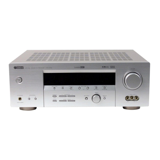
CONTROLS AND FUNCTIONS CONTROLS AND FUNCTIONS Front panel STANDBY PHONES SPEAKERS SILENT CINEMA 1 STANDBY/ON Turns on this unit or sets it to the standby mode. When you turn on this unit, you will hear a click and there will be a 4 to 5-second delay before this unit can reproduce sound. - Page 9 CONTROLS AND FUNCTIONS PHONES (SILENT CINEMA) jack Outputs audio signals for private listening with headphones. When you connect headphones, no signals are output to the OUTPUT jacks or to the speakers. All Dolby Digital and DTS audio signals are mixed down to the left and right headphone channels.
-
Page 10: Remote Control
CONTROLS AND FUNCTIONS Remote control This section describes the function of each control on the remote control used to control this unit. To operate other components, see “REMOTE CONTROL FEATURES” on page 51. CODE SET TRANSMIT POWER POWER STANDBY MD/CD-R TUNER DTV/CBL V-AUX... -
Page 11: Using The Remote Control
H STRAIGHT (EFFECT) Switches the sound fields off or on. When STRAIGHT is selected, input signals (2-channel or multi-channel) are output directly from their respective speakers without effect processing. I SET MENU (A/B/C/D/E) Activates the SET MENU function. Selects preset station groups when the unit is in tuner mode. -
Page 12: Front Panel Display
CONTROLS AND FUNCTIONS Front panel display SILENT CINEMA NIGHT MATRIX DISCRETE VIRTUAL DIGITAL PL x 1 Decoder indicators When any of this unit’s decoders function, the respective indicator lights up. 2 SILENT CINEMA indicator Lights up when headphones are connected and a sound field program is selected (see page 26). -
Page 13: Rear Panel
See page 15 for connection information. 3 Video component jacks See pages 14 and 16 for connection information. S VIDEO jacks are only available for HTR-5750. 4 AC OUTLET(S) Use to supply power to your other A/V components (see page 19). -
Page 14: Speaker Setup
Place this speaker directly behind the listening position and at the same height as the surround speakers. Subwoofer The use of a subwoofer, such as the YAMAHA Active Servo Processing Subwoofer System, is effective not only for reinforcing bass frequencies from any or all channels,... -
Page 15: Speaker Connections
Speaker connections Be sure to connect the left channel (L), right channel (R), “+” (red) and “–” (black) properly. If the connections are faulty, no sound will be heard from the speakers, and if the polarity of the speaker connections is incorrect, the sound will be unnatural and lack bass. - Page 16 SURROUND terminals Connect surround speakers to these terminals. SUB WOOFER jack Connect a subwoofer with built-in amplifier, such as the YAMAHA Active Servo Processing Subwoofer System, to this jack. SURROUND BACK terminals Connect a surround back speaker to these terminals.
-
Page 17: Connections
For component signals, separated into luminance (Y) and color difference (P picture reproduction. Note [ HTR-5750 only ] When signals are input through both the S VIDEO and VIDEO jacks, signals input through the S VIDEO jack have priority. CONNECTIONS... -
Page 18: Connecting Video Components
CONNECTIONS Signal flow inside this unit (HTR-5750) Input COMPONENT VIDEO S VIDEO VIDEO Only when V CONV. is set to ON (see page 49). Connecting video components Connections for DVD playback Optical out DVD player Audio out Signal flow inside this unit (HTR-5740) - Page 19 • This unit does not redirect signals input to the MULTI CH INPUT jacks to accommodate for missing speakers. We recommend that you connect at least a 5.1-channel speaker system before using this feature. • When headphones are used, only front left and right channels are output. (HTR-5750 U.S.A. model) FRONT SURROUND...
- Page 20 OPTICAL DTV/CBL VIDEO AUX jacks (on the front panel) Use these jacks to connect any video source, such as a game console or video camera, to this unit. Video out (HTR-5750 U.S.A. model) COMPONENT VIDEO AUDIO VIDEO VIDEO S VIDEO...
-
Page 21: Connecting Audio Components
Connecting audio components Connections for audio components Coaxial out Audio out CD player Optical in Optical out (HTR-5750 U.S.A. model) DIGITAL INPUT COAXIAL OPTICAL MD/CD-R ( PLAY ) /CD-R ( REC ) AUDIO MD/CD-R OPTICAL DIGITAL OUTPUT Audio out Audio in... -
Page 22: Connecting The Antennas
• A properly installed outdoor antenna provides clearer reception than an indoor one. If you experience poor reception quality, an outdoor antenna may improve the quality. Consult the nearest authorized YAMAHA dealer or service center about outdoor antennas. 75-ohm/300-ohm antenna adapter (U.K. -
Page 23: Connecting The Power Supply Cord
Connecting the power supply cord Connecting the AC power cord Plug the power cord into an AC wall outlet. AC OUTLET(S) (SWITCHED) U.K. and Australia models... 1 OUTLET Korea model... None Other models... 2 OUTLETS Use these outlets to connect the power cords from your other components to this unit. -
Page 24: Impedance Selector Switch
CONNECTIONS IMPEDANCE SELECTOR switch CAUTION Do not change the setting of the IMPEDANCE SELECTOR switch when the unit power is switched on, as doing so may damage the unit. If this unit fails to turn on when STANDBY/ON is pressed on either the front panel or remote control, the IMPEDANCE SELECTOR switch may not be fully slid to either position. -
Page 25: Turning On The Power
Turning on the power When all connections are complete, turn on the power of this unit. STANDBY l PRESET/TUNING h PRESET/TUNING FM/AM A/B/C/D/E MEMORY EDIT NEXT LEVEL MAN'L/AUTO FM INPUT PHONES SPEAKERS STRAIGHT PROGRAM INPUT MODE EFFECT CONTROL BASS/TREBLE SILENT CINEMA CODE SET TRANSMIT SYSTEM... -
Page 26: Basic Setup
BASIC SETUP The basic setup feature is a useful way to set up your system quickly and with minimal effort. • If you wish to configure the unit manually using more precise adjustments, use the detailed parameters in SOUND MENU (page 46) instead of using BASIC SETUP. - Page 27 Press d to display the SPEAKERS parameter. PRESET/CH SELECT Press j / i to select the number of speakers you connected. SPEAKERS 6spk Choices Display Front L/R 2spk SL SB SR SL SB SR Front L/R, Center L L C R 3spk SL SB SR Front L/R, Surround L/R...
- Page 28 BASIC SETUP To balance the speaker levels Perform the following steps after step 13 (see page 23). V-AUX DTV/CBL SILENT CINEMA NIGHT ZONE2 MATRIX DISCRETE VIRTUAL HiFi DSP DIGITAL SLEEP FR-----||----- PL x The unit outputs the test tone from the selected speaker and the left front (or left surround) speaker in turn.
-
Page 29: Playback
Basic operations STANDBY l PRESET/TUNING h PRESET/TUNING FM/AM A/B/C/D/E MEMORY EDIT NEXT LEVEL MAN'L/AUTO FM INPUT STRAIGHT PROGRAM PHONES SPEAKERS INPUT MODE EFFECT CONTROL BASS/TREBLE SILENT CINEMA CODE SET TRANSMIT SYSTEM POWER POWER POWER STANDBY TV VOL TV CH MD/CD-R TUNER SLEEP TV MUTE... - Page 30 PLAYBACK Select a sound field program if desired. Press PROGRAM l / h repeatedly (or press AMP on the remote control to select the AMP mode, then press one of the sound field program buttons repeatedly) to select a sound field program. (See page 39 for details about sound field programs.) PROGRAM Front panel...
-
Page 31: Selecting Sound Field Programs
Selecting MULTI CH INPUT Press MULTI CH INPUT so that “MULTI CH INPUT” appears in the front panel display and video monitor. MULTI CH INPUT Front panel MULTI CH INPUT Note When “MULTI CH INPUT” is shown in the front panel display, no other source can be played. -
Page 32: Remote Control Operation
PLAYBACK Remote control operation CODE SET TRANSMIT TV VOL TV CH SYSTEM POWER POWER STANDBY POWER TV MUTE TV INPUT MD/CD-R TUNER SLEEP STEREO HALL DTV/CBL V-AUX MULTI CH IN MUSIC ENTERTAIN q/DTS NIGHT TV VOL TV CH VOLUME PRESET/CH LEVEL TITLE TV MUTE... - Page 33 Notes • Some 6.1-channel compatible discs do not have a signal (flag) which this unit can automatically detect. When playing these kinds of discs with 6.1-channel, select a decoder manually (PLIIx Music, EX/ES or EX). • 6.1-channel playback is not possible even if EX/ES is pressed in the following cases: –...
- Page 34 PLAYBACK Listening to high fidelity stereo sound (Direct Stereo) Direct Stereo allows you to bypass this unit’s decoders and DSP processors to enjoy pure high fidelity sound from 2- channel PCM and analog sources. Press PROGRAM l / h repeatedly (or press AMP to select the AMP mode, then press STEREO repeatedly) to select “Direct Stereo”.
-
Page 35: Selecting Input Modes
Downmixing to 2 channels You can enjoy 2-channel stereo playback even from multi- channel sources. Press PROGRAM l / h repeatedly (or press STEREO on the remote control) to select 2ch Stereo. STEREO PROGRAM MUSIC q/DTS Front panel Remote control 2ch Stereo You can use a subwoofer with this program when SWFR or BOTH is selected in “BASS OUT”. - Page 36 PLAYBACK Notes • When you play DTS-encoded CD/LDs with the input mode set to AUTO: – This unit automatically switches to the DTS decoding mode. The unit remains in DTS mode (and the t indicator may flash) for up to 30 seconds after playback of the DTS source is complete.
-
Page 37: Tuning
Automatic and manual tuning There are 2 tuning methods; automatic and manual. Automatic tuning is effective when station signals are strong and there is no interference. Automatic tuning STANDBY A/B/C/D/E l PRESET/TUNING h MEMORY TUNING MODE PRESET/TUNING FM/AM EDIT NEXT LEVEL MAN'L/AUTO FM INPUT... -
Page 38: Presetting Stations
TUNING Manual tuning If the signal from the station you want to select is weak, tune into it manually. Manually tuning into an FM station will automatically switch the tuner to monaural reception to increase the signal quality. Select TUNER and the reception band following steps 1 and 2 as described in “Automatic tuning”. - Page 39 Press and hold MEMORY (MAN’L/AUTO FM) for more than 3 seconds. The preset number, the MEMORY and AUTO indicators flash. After about 5 seconds, automatic presetting starts from the frequency currently displayed and proceeds toward the higher frequencies. MEMORY MAN'L/AUTO FM V-AUX DTV/CBL MD/CD-R...
-
Page 40: Selecting Preset Stations
TUNING Press PRESET/TUNING l / h to select a preset station number (1 through 8) while the MEMORY indicator is flashing. Press h to select a higher preset station number. Press l to select a lower preset station number. l PRESET/TUNING h LEVEL V-AUX DTV/CBL... -
Page 41: Exchanging Preset Stations
Exchanging preset stations You can exchange the assignment of two preset stations with each other. The example below describes the procedure for exchanging preset station “E1” with “A5”. STANDBY l PRESET/TUNING h MEMORY TUNING MODE PRESET/TUNING FM/AM A/B/C/D/E EDIT NEXT LEVEL MAN'L/AUTO FM INPUT... -
Page 42: Recording
VOLUME • A source connected to the MULTI CH INPUT jacks of this unit cannot be recorded. • [ HTR-5750 only ] S-Video and composite video signals pass TUNING MODE AUTO/MAN'L MONO independently through this unit’s video circuits. Therefore,... -
Page 43: Sound Field Program Descriptions
The YAMAHA CINEMA DSP modes are compatible with all Dolby Digital, DTS, and Dolby Surround sources. Set the input mode to AUTO (see page 31) to enable this unit to automatically switch to the appropriate digital decoder according to the input signal. -
Page 44: Dolby Digital
SOUND FIELD PROGRAM DESCRIPTIONS Program DOLBY DIGITAL Standard 5.1-channel processing for Dolby Digital sources. SUR. STANDARD DOLBY DIGITAL CINEMA DSP enhanced processing for Dolby Digital sources. SUR. ENHANCED DOLBY D EX Standard 6.1-channel processing for Dolby Digital sources. SUR. STANDARD DOLBY D EX CINEMA DSP enhanced 6.1-channel processing (Dolby Digital EX) for Dolby Digital sources. -
Page 45: For Music Sources
For music sources You can select from the following sound fields when playing music sources, like CD, FM/AM broadcasting, tapes, etc. Program CONCERT HALL HiFi DSP processing. A classic shoe-box type concert hall with approximately 1700 seats. Pillars and ornate carvings create extremely complex reflections which produce a very full, rich sound. -
Page 46: Advanced Operation
ADVANCED OPERATIONS Using the sleep timer Use this feature to automatically set this unit in the standby mode after a certain amount of time. The sleep timer is useful when you are going to sleep while this unit is playing or recording a source. The sleep timer also automatically turns off any external components connected to the AC OUTLET(S). -
Page 47: Manually Adjusting Speaker Levels
Manually adjusting speaker levels You can adjust the output level of each speaker while listening to a music source. This is also possible when playing sources through the MULTI CH INPUT jacks. Please note that this operation will override the level adjustments made in “BASIC SETUP”... -
Page 48: Set Menu
SET MENU You can use the following parameters in SET MENU to adjust a variety of system settings and customize the way this unit operates. Change the initial settings (indicated in bold under each parameter) to reflect the needs of your listening environment. -
Page 49: Using Set Menu
Using SET MENU Use the remote control to access and adjust each parameter. TV VOL TV CH VOLUME TV MUTE TV INPUT MUTE STEREO HALL JAZZ ROCK MUSIC ENTERTAIN TV THTR MOVIE q/DTS NIGHT EX/ES STRAIGHT ENTER EFFECT PRESET/CH SET MENU LEVEL TITLE MENU... -
Page 50: Sound Menu
SET MENU 1 SOUND MENU Use to manually adjust any speaker setting or compensate for video signal processing delays when using LCD monitors or projectors. Most of the SOUND MENU parameters are set automatically when you perform “BASIC SETUP” (see page 22). Speaker set A)SPEAKER SET Use to manually adjust any speaker setting. - Page 51 Speaker level B)SP LEVEL Use these settings to manually balance the speaker levels between the front left or surround left speakers and each speaker selected in SPEAKER SET (page 46). Choices: –10.0 dB to +10.0 dB • FR adjusts the balance of the front left and front right speakers.
-
Page 52: Input Menu
For COMPONENT VIDEO jacks A (C.V[A]) and B (C.V[B]) Choices: DVD, V-AUX, DTV/CBL, VCR [ HTR-5750 ] For OPTICAL OUTPUT jack 1 (OUT(1)) Choices: MD/CD-R, CD, V-AUX, DTV/CBL, VCR, DVD For OPTICAL INPUT jacks 2 (IN(2)), 3 (IN(3)) -
Page 53: Option Menu
Dimmer DIMMER Use to adjust the brightness of the front panel display. Choices: –4 to 0 Video conversion (HTR-5750 only) V CONV. Use this feature to turn on/off conversion of composite (VIDEO) signals to S-Video signals. This allows you to output converted video signals from the S VIDEO jacks when no S-Video signals are input. - Page 54 SET MENU Parameter initialization Use this feature to initialize the parameters for each sound program within a sound program group. When field field you initialize a sound program group, all of the field parameter values within that group revert to their initial settings.
-
Page 55: Remote Control Features
REMOTE CONTROL FEATURES In addition to controlling this unit, the remote control can also operate other A/V components made by YAMAHA and other manufacturers. To control other components, you must set up remote control with the appropriate manufacturer codes. Control area... -
Page 56: Setting Manufacturer Codes
– – Note You may not be able to operate your YAMAHA component even if a YAMAHA manufacturer code is initially set as listed above. In this case, try to set other YAMAHA manufacturer code(s). Press an input selector button or select the component you want to set up. -
Page 57: Controlling Other Components
Controlling other components Once you set the appropriate manufacturer codes, you can use this remote to control your other components. Note that some buttons may not correctly operate the selected component. Use the input selector buttons to select the component you want to operate. The remote control automatically switches to the appropriate control mode for that component. -
Page 58: Clearing Setup Manufacturer Codes
REMOTE CONTROL FEATURES Clearing setup manufacturer codes Clearing a setup manufacturer code for component control Press an input selector button or select the component control for which you want to clear the manufacturer code. MD/CD-R TUNER DTV/CBL V-AUX Press CODE SET using a ballpoint pen or similar object. -
Page 59: Editing Sound Field Parameters
The acoustics in your room could be changed to those of a concert hall, a dance floor, or virtually any size room at all. This ability to create sound fields at will is exactly what YAMAHA has done with the digital sound field processor. EDITING SOUND FIELD PARAMETERS... - Page 60 EDITING SOUND FIELD PARAMETERS Repeat steps 2 through 4 as necessary to change other program parameters. Note You cannot change parameter values when “MEMORY GUARD” is set to ON. If you want to change the parameter values, set “MEMORY GUARD” to OFF (see page 49). Memory back-up The memory back-up circuit prevents the stored data from being lost even if this unit is set in the standby...
-
Page 61: Sound Field Parameter Descriptions
SOUND FIELD PARAMETER DESCRIPTIONS You can adjust the values of certain digital sound field parameters so the sound fields are recreated accurately in your listening room. Not all of the following parameters are found in every program. DSP LEVEL Function: This parameter adjusts the level of all the DSP effect sounds within a narrow range. - Page 62 SOUND FIELD PARAMETER DESCRIPTIONS For PRO LOGIC IIx Music and PRO LOGIC II Music PANORAMA Function: Extends the front stereo image to include the surround speakers for wraparound effect. Choices: OFF/ON, initial setting is OFF. DIMENSION Function: Gradually adjusts the sound field either towards the front or towards the rear. Control range: –3 (towards the rear) to +3 (towards the front), initial setting is STD (standard).
-
Page 63: Troubleshooting
Press MUTE or any operation buttons of this unit to cancel a mute and adjust the volume. Set the input mode to AUTO or DTS. Play a source whose signals this unit can reproduce. Turn on the video conversion function (HTR-5750 only). TROUBLESHOOTING Refer to... - Page 64 TROUBLESHOOTING Problem The sound suddenly The protection circuitry has been activated goes off. because of a short circuit, etc. The sleep timer has turned the unit off. The sound is muted. Only the speaker on Incorrect cable connections. one side can be heard.
- Page 65 The sound effect It is not possible to record the sound effect cannot be recorded. with a recording component. [ HTR-5750 ] The source component is not connected to this unit’s DIGITAL INPUT jacks. A source cannot be recorded by a digital...
- Page 66 TROUBLESHOOTING Tuner Problem FM stereo reception is The characteristics of FM stereo noisy. broadcasts may cause this problem when the transmitter is too far away or the antenna input is poor. There is distortion, and There is multipath interference. clear reception cannot be obtained even with a good FM antenna.
-
Page 67: Resetting The Factory Presets
RESETTING THE FACTORY PRESETS If you want to reset all of your unit’s parameters for any reason, do the following. This procedure completely resets ALL parameters, including the SET MENU, level, assign and tuner presets. Be sure this unit is in standby mode. STANDBY l PRESET/TUNING h PRESET/TUNING... -
Page 68: Glossary
GLOSSARY Audio formats Dolby Digital Dolby Digital is a digital surround sound system that gives you completely independent multi-channel audio. With 3 front channels (left, center, and right), and 2 surround stereo channels, Dolby Digital provides 5 full-range audio channels. With an additional channel especially for bass effects, called LFE (low frequency effect), the system has a total of 5.1-channels (LFE is counted as 0.1 channel). -
Page 69: Sound Field Programs
SILENT CINEMA YAMAHA has developed a natural, realistic sound effect DSP algorithm for headphones. Parameters for headphones have been set for each sound field so that accurate representations of all the sound field programs can be enjoyed on headphones. -
Page 70: Video Signal Information
GLOSSARY Video signal information Component video signal With the component video signal system, the video signal is separated into the Y signal for the luminance and the P and P signals for the chrominance. Color can be reproduced more faithfully with this system because each of these signals is independent. -
Page 71: Specifications
• Frequency Response (MONITOR OUT) Composite ... 5 Hz to 10 MHz, –3 dB Component ... 5 Hz to 60 MHz, –3 dB S-Video (HTR-5750 only) ... 5 Hz to 10 MHz, –3 dB FM SECTION • Tuning Range [U.S.A. and Canada models] ... 87.5 to 107.9 MHz [Other models] ... - Page 72 LIST OF MANUFACTURER CODES DAYTRON DECCA A TANDY 0941 DIXI ABEX 1151 DUMONT ADMIRA 1141 DYNATECH ADVENTURA 1131 ELECTROBAND AIKO 1121 ELECTROHOME AIWA 1481 ELECTRON AKAI 0331, 1101, 1111 ELIN ALBA 0431 ELTA ALLERON 1091 EMERSON AMBASSADOR 1081 AMSTRAD 0481, 1081 ANAM 0251, 1041, 1051, 1061, 1071...
- Page 73 SEARS 0101, 0161, 0171, 0351, 0481, 0521, 0621, 0761, 0801, 0861, 0971, 0981, WATSON 1091 XOGEGO SHANGHAI 1561, 1681 SHARP 0461, 0471, 0541, YAMAHA 0661, 0911, 0941, YOKO 1141 ZENITH SHOGUN 1031 SIGNATURE 0991, 1771 ZONDA SIMPSON 0581, 0961 SOLAVOX...
-
Page 74: Dvd Player
VIDEO CONCEPTS PHILCO 0002, 0932 PHILIPS 0002, 0282, 0402, 0492, 0932 WARDS PILOT 0912 PIONEER 0442, 0542 1002, 1012, 1022, YAMAHA 0202, 0632 1032, 1042, 1052, ZENITH 0042, 0362, 0512, 1062 0672 0512 0612 DVD PLAYER 0272, 0612 0382, 0392, 0932... - Page 75 0345 SHARP SHARP 0235, 0665, 0895, SHERWOOD 1065, 1075 SONY SHERWOOD 0115, 0235, 0395, TEAC 0475 TECHNICS SIEMENTS GARRARD WARDS 1245 YAMAHA SIGNATURE 0175 SONTEC 1165 SONY 0065, 0565, 0865, 1145 STARON 1235 0025 SYLVANIA 0215 SYMPHONIC 0335 TANDY 0305...
- Page 76 YAMAHA ELECTRONICS (UK) LTD. YAMAHA HOUSE, 200 RICKMANSWORTH ROAD WATFORD, HERTS WD18 7GQ, ENGLAND YAMAHA SCANDINAVIA A.B. J A WETTERGRENS GATA 1, BOX 30053, 400 43 VÄSTRA FRÖLUNDA, SWEDEN YAMAHA MUSIC AUSTRALIA PTY, LTD. 17-33 MARKET ST., SOUTH MELBOURNE, 3205 VIC., AUSTRALIA...