Table of Contents
Advertisement
Operation Manual
XLS Series
Obtaining Other Language Versions: To obtain information in another language about the use of this product, please contact your
local Crown Distributor. If you need assistance locating your local distributor, please contact Crown at 574-294-8000.
This manual does not include all of the details of design, production, or variations of the equipment. Nor does it cover every possible
situation which may arise during installation, operation or maintenance.
The information provided in this manual was deemed accurate as of the publication date. However, updates to this information may have
occurred. To obtain the latest version of this manual, please visit the Crown website at www.crownaudio.com.
Trademark Notice: Crown and Amcron are registered trademarks of Crown International. Other trademarks are the property of their
respective owners.
Some models may be exported under the name Amcron.
©2004 by Crown Audio Inc., P.O. Box 1000, Elkhart, Indiana 46515-1000 U.S.A. Telephone: 574-294-8000
®
XLS 202
XLS 402
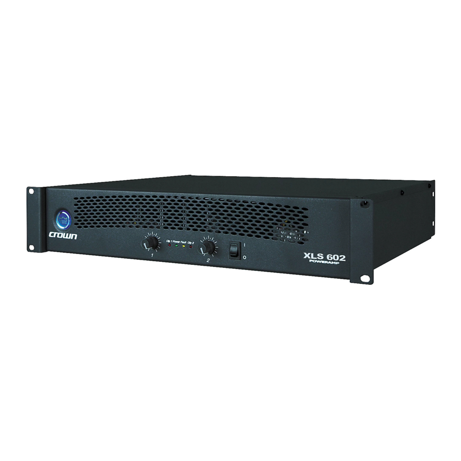
XLS 602
133465-6
1/04
Advertisement
Table of Contents

Related Manuals for Crown XLS Series


Summary of Contents for Crown XLS Series
- Page 1 To obtain the latest version of this manual, please visit the Crown website at www.crownaudio.com. Trademark Notice: Crown and Amcron are registered trademarks of Crown International. Other trademarks are the property of their respective owners. ©2004 by Crown Audio Inc., P.O. Box 1000, Elkhart, Indiana 46515-1000 U.S.A. Telephone: 574-294-8000 XLS Series ®...
-
Page 2: Important Safety Instructions
TIES SERVICEABLE À L’INTÉRIEUR. TOUS REPA- RATIONS DOIT ETRE FAIRE PAR PERSONNEL QUALIFIÉ SEULMENT. IMPORTANT XLS Series amplifiers require Class 2 output wiring. MAGNETIC FIELD CAUTION! Do not locate sensitive high-gain equip- ment such as preamplifiers or tape decks directly above or below the unit. -
Page 3: Declaration Of Conformity
XLS Series Power Amplifiers Crown International, Inc. Issued By: Crown International, Inc. 1718 W. Mishawaka Road Elkhart, Indiana 46517 U.S.A. European Representative’s Name and Address: Nick Owen 19 Clos Nant Coslech Pontprennau Cardiff CF23 8ND United Kingdom Equipment Type: Commercial Audio Power Amplifiers... -
Page 4: Table Of Contents
3.2 Front Panel Controls and Indicators ... 12 3.3 Back Panel Controls and Connectors... 13 4 Advanced Features and Options ... 14 page 4 XLS Series Power Amplifiers 4.1 Protection Systems ... 14 4.1.1 Output Current Limiting... 14 4.1.2. DC Protection ... 14 4.1.3 Circuit Breaker... -
Page 5: Welcome
Please take the time to study this manual so that you can obtain the best possible service from your amplifier. The XLS Series of power amplifiers from Crown represents a new era in affordable, quality 1.1 Features power amplification. The line consists of three •Simple, reliable design incorporates many... -
Page 6: Setup
NOTE: When transporting, amplifiers should be supported at both front and back. Figure 2.1 Dimensions XLS Series Power Amplifiers 2.3 Ensure Proper Cooling When using an equipment rack, mount units directly on top of each other. Close any open spaces in rack with blank panels. DO NOT block front, rear or side air vents. -
Page 7: Choose Input Wire And Connectors
XLS Series Power Amplifiers 2 Setup 2.4 Choose Input Wire and Connectors Crown recommends using pre-built or professionally wired bal- anced line (two-conductor plus shield), 22-24 gauge cables and connectors. You should use 3-pin male XLR cable ends at the amplifier inputs. -
Page 8: Wire Your System
Loudspeaker 1– Bottom 2– Speakon (Channel 2) Figure 2.9 Stereo Wiring Method 2: Connect Each Speaker to a Different Speakon Connector XLS Series Power Amplifiers Figure 2.7 System Wiring, Stereo Mode Using the 5-way Binding Posts Top Speakon (Channel 1) -
Page 9: Bridge-Mono Mode
XLS Series Power Amplifiers 2 Setup 2.6.2 Bridge-Mono Mode INPUTS: Use a custom “Y” adapter cable, wired to split the signal and invert the polarity for the Channel 2 amplifier input as shown in Figure 2.10. We recommend you label the ends of the Y adapter to help make sure to connect the correct end to each amplifier input. -
Page 10: Connect To Ac Mains
75 Hz for speech. On each mixer input channel, set the filter frequency just below the lowest fundamen- tal frequency of that channel's instrument. page 10 XLS Series Power Amplifiers 2.9 Startup Procedure Use the following procedure when first turning on your amplifier: 1. -
Page 11: Operation
XLS Series Power Amplifiers 3 Operation 3.1 Precautions Your amplifier is protected from internal and exter- nal faults, but you should still take the following precautions for optimum performance and safety: 1. Before use, your amplifier first must be config- ured for proper operation, including input and output wiring hookup. -
Page 12: Front Panel Controls And Indicators
Also illuminates briefly during normal power-up when amplifier is first switched on. F. Power Switch Amplifier is on when the switch is in the UP position. Figure 4.1 Front Panel Controls and Indicators XLS Series Power Amplifiers Operation Manual... -
Page 13: Back Panel Controls And Connectors
XLS Series Power Amplifiers 3 Operation 3.3 Back Panel Controls and Connectors G. Power Connector H. Circuit Breaker Provides overload protection. I. Balanced XLR Inputs Two 3-pin female XLR input connectors are provided (one per channel). J. Fans Provide front-to-back forced airflow for cool- ing. -
Page 14: Advanced Features And Options
5) Heatsinks in need of cleaning 6) Cooling fan failure. The cause of your amplifier’s thermal protection state should be determined and corrected as soon as possible. Without correction, the Ther- mal Protection circuit will typically reactivate. XLS Series Power Amplifiers Operation Manual... -
Page 15: Troubleshooting
XLS Series Power Amplifiers 5 Troubleshooting CONDITION: Normal operation. POSSIBLE REASON: • This is normal operation for your amp. CONDITION: No power to the amplifier. POSSIBLE REASON: • The amplifier’s Power switch is off. • The amplifier is not plugged into the power receptacle. -
Page 16: Specifications
–10°, +19° –10°, +19° > 100 dB > 100 dB > 95 dB > 95 dB < 0.5% < 0.5% < 0.3% < 0.3% XLS Series Power Amplifiers XLS 602 840W 600W 370W 1,200W 1,680W 880W 670W 1,760W XLS 602 1.26... - Page 17 XLS Series Power Amplifiers 6 Specifications Performance Damping Factor (8 ohm): 10 Hz to 400 Hz Crosstalk (below rated power, at 1 kHz at 20 kHz DC Output Offset (Shorted input) Input Impedance (nominally balanced, nominally unbalanced) Load Impedance (Note: Safe with all types of loads)
-
Page 18: Ac Power Draw And Thermal Dissipation
• Duty cycle of continuous speech is 10%. • Duty cycle of infrequent, short duration paging is 1%. page 18 XLS Series Power Amplifiers Here are the equations used to calculate the data presented in Figures 7.1, 7.2 and 7.3:... - Page 19 XLS Series Power Amplifiers 7 AC Power Draw and Thermal Dissipation 2 Ohm Stereo Current Draw (Amps) Mains Duty Power Cycle Draw 120V 230V 2 Ohm Stereo Current Draw (Amps) Mains Duty Power Cycle Draw 120V 230V 1023 10.0 Operation Manual...
- Page 20 Draw 120V 230V btu/hr kcal/hr 1774 1437 1100 Figure 7.3 XLS 602 Power Draw, Current Draw and Thermal Dissipation at Various Duty Cycles XLS Series Power Amplifiers 8 Ohm Stereo Thermal Current Draw Dissipation (Amps) Mains Power Draw 120V 230V...
-
Page 21: Service
XLS Series Power Amplifiers 8 Service Crown amplifiers are quality units that rarely require servicing. Before returning your unit for servicing, please contact Crown Technical Sup- port to verify the need for servicing. This unit has very sophisticated circuitry which should only be serviced by a fully trained tech- nician. -
Page 22: Warranty
DISCLAIMER OF CONSEQUENTIAL AND INCIDENTAL DAMAGES THIS STATEMENT OF WARRANTY SUPERSEDES ANY OTHERS CONTAINED IN THIS MANUAL YOU ARE NOT ENTITLED TO RECOVER FROM FOR CROWN PRODUCTS. US ANY INCIDENTAL DAMAGES RESULTING XLS Series Power Amplifiers 12/01 Operation Manual... - Page 23 XLS Series Power Amplifiers 9 Warranty SUMMARY OF WARRANTY Crown International, 1718 West Mishawaka Road, Elkhart, Indiana 46517-4095 U.S.A. warrants to you, the ORIGINAL PURCHASER and ANY SUB- SEQUENT OWNER of each NEW Crown1 product, for a period of three (3) years from the date of pur- chase by the original purchaser (the “warranty...
- Page 24 XLS Series Power Amplifiers THIS PAGE INTENTIONALLY LEFT BLANK page 24 Operation Manual...
-
Page 25: Crown Factory Service Information Form
XLS Series Power Amplifiers Owner’s Name : _________________________________________________________________________________________________________________________________________________________________ Shipping Address: _______________________________________________________________________________________________________________________________________________________________ Phone Number: ________________________________Fax Number: ________________________________ Email ________________________________________________________________________________ Model: __________________________________________________________________________________ Serial Number: _________________________________________________________________________ Purchase Date : _________________________________________________________________________________________________________________________________________________________________ _______________________________________________________________________________________________________________________________________________________________________________ _______________________________________________________________________________________________________________________________________________________________________________ _______________________________________________________________________________________________________________________________________________________________________________ _______________________________________________________________________________________________________________________________________________________________________________ _______________________________________________________________________________________________________________________________________________________________________________ _______________________________________________________________________________________________________________________________________________________________________________ _______________________________________________________________________________________________________________________________________________________________________________ _______________________________________________________________________________________________________________________________________________________________________________ Other equipment in system:____________________________________________________________________________________________________________________________________________________________ _______________________________________________________________________________________________________________________________________________________________________________... - Page 26 XLS Series Power Amplifiers THIS PAGE INTENTIONALLY LEFT BLANK page 26 Operation Manual...
- Page 27 XLS Series Power Amplifiers NOTES Operation Manual page 27...