Table of Contents
Advertisement
Quick Links
AIR CONDITIONER (MULTI TYPE)
Installation Manual
Scan QR CODE to access installation and owner's manual on website.
https://www.toshiba-carrier.co.th/manuals/default.aspx
Manual are available in AR/BG/CZ/DA/DE/EL/EN/ES/ET/FI/FR/
HR/HU/IT/LT/LV/NL/NO/PL/PT/RO/RU/SK/SL/SV/TR.
Indoor Unit
Model name:
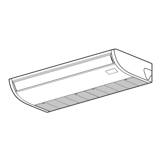
Ceiling Type
MMC-UP0151HP-E
MMC-UP0181HP-E
MMC-UP0241HP-E
MMC-UP0271HP-E
MMC-UP0361HP-E
MMC-UP0481HP-E
MMC-UP0561HP-E
For commercial use
English
Advertisement
Table of Contents

Related Manuals for Toshiba MMC-UP0151HP-E


Summary of Contents for Toshiba MMC-UP0151HP-E
- Page 1 Indoor Unit AIR CONDITIONER (MULTI TYPE) For commercial use Installation Manual Model name: Ceiling Type MMC-UP0151HP-E MMC-UP0181HP-E MMC-UP0241HP-E MMC-UP0271HP-E MMC-UP0361HP-E MMC-UP0481HP-E MMC-UP0561HP-E Scan QR CODE to access installation and owner’s manual on website. https://www.toshiba-carrier.co.th/manuals/default.aspx Manual are available in AR/BG/CZ/DA/DE/EL/EN/ES/ET/FI/FR/ HR/HU/IT/LT/LV/NL/NO/PL/PT/RO/RU/SK/SL/SV/TR.
-
Page 2: Table Of Contents
– 1 – Original instruction Please read this Installation Manual carefully before installing the Air Conditioner. • This Manual describes the installation method of the indoor unit. • For installation of the outdoor unit, follow the Installation Manual attached to the outdoor unit. Contents 1 Accessory parts ...................... -
Page 3: Accessory Parts
CAUTION Accessory parts Do not install in a location where fl ammable gas may leaks are possible. • If the gas leak and accumulate around the unit, it may ignite and cause a fi re. Part name Q’ty Shape Usage When an outdoor unit using R32 refrigerant is combined with indoor unit, be attention to the fl... -
Page 4: Installation
– 3 – ■ Installation space (Unit: mm) Installation Reserve suffi cient space required for installation or service work. CAUTION Strictly comply with the following rules to prevent damage of the indoor units and human injury. • Do not put a heavy article on the indoor unit or let a person get on it. (Even units are packaged) 250 or more 250 or more •... - Page 5 ■ ■ Installation of hanging bolt Installation of hanging bolt Before installation CAUTION Use M10 hanging bolts (4 pcs, locally procured). • Consider the piping / wiring after the unit is hung to Removal of air intake grille Matching to the existing structure, set pitch according determine the location of the indoor unit installation 1) Remove the screws of air intake grille fi...
- Page 6 – 5 – ■ ■ Draw-out direction of pipe / <In case of taking pipe from upper side> Installation of indoor unit ◆ Holding down of main unit Taking pipe from upper side is applied only to the wire refrigerant pipe. <Hanging the indoor unit directly from the ◆...
-
Page 7: Drain Piping
◆ Attaching the hanging bracket Attach the indoor unit onto the hanging Drain piping fi rst bracket and fasten it tight with the bolts and screws. bracket Remove the screws fastening hanging onto the indoor unit. CAUTION Following the Installation Manual, perform the drain piping work so that water is properly drained. Apply a heat insulation so as not to cause a dew condensation. - Page 8 – 7 – ■ ■ Connection of drain hose Heat insulating process • Insert the attached drain hose into the drain pipe connecting port on the drain pan up to the end. • Using the attached drain hose heat insulator, lap the connecting section and the drain hose without clearance, •...
-
Page 9: Refrigerant Piping
■ Connecting refrigerant piping Refrigerant piping CAUTION Flaring • Do not scratch the inner surface of the fl ared part ■ when removing burrs. Take out direction of Cut the pipe with a pipe cutter. CAUTION • Flare processing under the condition of scratches Remove burrs completely. -
Page 10: Electrical Connection
– 9 – ■ Evacuation Open the valve fully Electrical connection Open the valve of the outdoor unit fully. A 4 mm- Perform vacuuming from the charge port of valve of hexagonal wrench is required for opening the valve. the outdoor unit by using a vacuum pump. For details, refer to the Installation Manual attached to For details, follow to the Installation Manual attached to WARNING... - Page 11 ▼Power supply <In the case of combining with outdoor units of Super Modular Multi System u series (SMMS-u)> 220-240V ~, 50 Hz Uv line and Uc line (L2, L3, L4) 0.5 mm² (Up to 500 m) Power supply Wire size : 208-230V ~, 60 Hz (2-core shield wire, non-polarity) 0.75 to 1.25 mm²...
- Page 12 – 11 – <In the case of combining with outdoor units other than Super Modular Multi System u series (SMMS-u)> Remote controller wiring Control wiring between indoor units, and outdoor unit (L2, L3) • 2-core with non-polarity wire is used for wiring of the remote controller wiring and group remote controllers wiring. (2-core shield wire, non-polarity) 1.25 mm²...
- Page 13 ■ ◆ Wire connection Remote controller wiring Strip off approx. 9 mm the wire to be connected. REQUIREMENT Wiring diagram • Connect the wires matching the terminal numbers. Incorrect connection causes a trouble. • Pass the wires through the bushing of wire connection holes of the indoor unit. Terminal block for •...
-
Page 14: Applicable Controls
– 13 – ■ Wiring between indoor and outdoor units Applicable controls NOTE ■ Applicable controls setup REQUIREMENT A wiring diagram below is an example for connection to SMMS-u series. For connecting to other outdoor unit (settings at the site) series, refer to the Installation Manual attached to the outdoor unit to be connected. - Page 15 ■ ■ ■ Installing indoor unit on high Filter sign setting Group control Each time [ ] setting button is ceiling pushed, indoor unit numbers in the group According to the installation condition, the fi lter sign In a group control, a remote controller can control up to control change cyclically.
-
Page 16: Test Run
– 15 – Wired remote controller Wireless remote controller Test run Be sure to stop the air conditioner before making settings. NOTE (Change the setup while the air conditioner is not ■ Before test run • Be sure to operate the unit, following the instruction working.) manual •... -
Page 17: Maintenance
▼Periodic Maintenance Maintenance • For environmental conservation, it is strongly recommended that the indoor and outdoor units of the air conditioner in use be cleaned and maintained regularly to ensure effi cient operation of the air conditioner. When the air conditioner is operated for a long time, periodic maintenance (once a year) is recommended. <Daily maintenance>... -
Page 18: Troubleshooting
– 17 – Troubleshooting Confi rmation and check If a problem occurs with the air conditioner, the OFF timer indicator alternately shows the check code and the indoor Unit No. in which the problem occurred. Check code The indoor Unit No. in which the problem occurred. - Page 19 Check method On the wired remote controller, central control remote controller and the interface P.C. Board of the outdoor unit (I/F), a check display LCD (Remote controller) or 7-segment display (on the outdoor interface P.C. Board) to display the operation is provided.
- Page 20 – 19 – Check code Wireless remote controller Outdoor unit 7-segment display Sensor block display of receiving unit Check code name Judging device Wired remote controller display Auxiliary code Operation Timer Ready Flash 01: TE1 sensor 02: TE2 sensor TE1,TE2 or TE3 sensor trouble 03: TE3 sensor 01: TL1 sensor 02: TL2 sensor...
- Page 21 Check code Wireless remote controller Outdoor unit 7-segment display Sensor block display of receiving unit Check code name Judging device Wired remote controller display Auxiliary code Operation Timer Ready Flash ─ ─ Duplicated Flow Selector unit addresses Indoor unit Detected indoor unit address Flow Selector unit overfl...
- Page 22 – 21 – Check code Wireless remote controller Outdoor unit 7-segment display Sensor block display of receiving unit Check code name Judging device Wired remote controller display Auxiliary code Operation Timer Ready Flash ─ Discharge temp. TD2 trouble ─ Discharge temp. TD3 trouble 0#: 4-way valves 1#: 4-way valve1 4-way valve inverse trouble...
-
Page 23: Specifi Cations
The existing R22 and R410A piping can be reused for Cooling Heating There is the possibility that copper green rust has inverter R32 product installations. MMC-UP0151HP-E been generated. MMC-UP0181HP-E WARNING 6. When the existing air conditioner is removed after refrigerant has been recovered. - Page 24 – 23 – Existing pipes: Cannot be used. Are there scratches or dents on the existing pipes? Use new pipes. Is it possible to operate the existing air conditioner? After the existing air conditioner is operated in cooling mode for approx. 30 minutes or longer, * recover the refrigerant.
- Page 25 Declaration of Conformity Declaration of Conformity Manufacturer: Toshiba Carrier (Thailand) Co.,Ltd. Manufacturer: Toshiba Carrier (Thailand) Co.,Ltd. 144 / 9 Moo 5, Bangkadi Industrial Park, Tivanon Road, Tambol Bangkadi, 144 / 9 Moo 5, Bangkadi Industrial Park, Tivanon Road, Tambol Bangkadi,...
- Page 26 – 25 – Warnings on Refrigerant Leakage Important 2) When there is an effective opening with the adjacent room for ventilation of leaking refrigerant gas (opening Check of Concentration Limit without a door, or an opening 0.15 % or larger than the respective fl oor spaces at the top or bottom of the door). The room in which the air conditioner is to be installed requires a design that in the event of refrigerant gas leaking out, its concentration will not exceed a set limit.
- Page 27 144 / 9 Moo 5, Bangkadi Industrial Park, Tivanon Road, Tambol Bangkadi, Amphur Muang, Pathumthani 12000, Thailand 1115652723...