Table of Contents
Advertisement
Quick Links
Advertisement
Table of Contents

Related Manuals for Danfoss VACON NXP IP00


Summary of Contents for Danfoss VACON NXP IP00
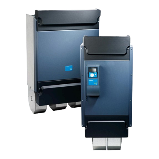
- Page 1 Operating Guide VACON® NXP IP00 Drive Modules drives.danfoss.com...
-
Page 3: Table Of Contents
Lifting the AC Chokes Using the Product Modified Label Mounting the Unit Environmental Requirements Cooling Requirements 5.2.1 Ventilation of the Cabinet 5.2.2 Steering the Internal Airflow 5.2.3 Heat Dissipation 5.2.4 Temperatures Measured during Test Run Danfoss A/S © 2023.09 AQ351737303996en-000201/DPD00888 | 3... - Page 4 Installing the Cables, FR11 6.7.6 Installing the Cables, FR13/FR14 Control Unit Control Unit Components Control Voltage (+24 V/EXT +24 V) Control Unit Cabling 7.3.1 Selection of the Control Cables 7.3.2 Control Terminals on OPTA1 4 | Danfoss A/S © 2023.09 AQ351737303996en-000201/DPD00888...
- Page 5 Fault Time Data Record Using the Fault History Menu (M5) 8.6.1 Fault History Menu (M5) 8.6.2 Resetting the Fault History Using the System Menu (M6) 8.7.1 Finding the System Menu 8.7.2 System Menu Functions Danfoss A/S © 2023.09 AQ351737303996en-000201/DPD00888 | 5...
- Page 6 Changing the HMI Acknowledge Timeout 8.7.8.7 Changing the Number of Retries to Receive HMI Acknowledgement (P6.7.4) 8.7.8.8 Sine Filter (P6.7.5) 8.7.8.9 Pre-charge Mode (P6.7.6) 8.7.9 System Info 8.7.9.1 Finding the System Info Menu 8.7.9.2 Total Counters (S6.8.1) 6 | Danfoss A/S © 2023.09 AQ351737303996en-000201/DPD00888...
- Page 7 Maintenance 10.1 Preventive Maintenance Recommendations 10.2 Reforming the Capacitors Fault Tracing 11.1 General Information on Fault Tracing 11.2 Resetting a Fault 11.3 Creating Service Info File 11.4 Error Message on Control Panel Display Danfoss A/S © 2023.09 AQ351737303996en-000201/DPD00888 | 7...
- Page 8 Tightening Torques for Cover Screws 12.8 Tightening Torques of the Terminals 12.9 Power Ratings 12.9.1 Overload Capability 12.9.2 Power Ratings for Mains Voltage 380–500 V 12.9.3 Power Ratings for Mains Voltage 500–690 V 8 | Danfoss A/S © 2023.09 AQ351737303996en-000201/DPD00888...
- Page 9 Brake Chopper Ratings 12.11.1 Brake Chopper Ratings for Mains Voltage 208–240 V 12.11.2 Brake Chopper Ratings for Mains Voltage 380–500 V 12.11.3 Brake Chopper Ratings for Mains Voltage 525–690 V 12.12 Faults and Alarms Danfoss A/S © 2023.09 AQ351737303996en-000201/DPD00888 | 9...
-
Page 10: Introduction
Table 1: Manual Version Edition Remarks DPD00888B New structure throughout the manual. 1.5 Type Approvals and Certifications The following list is a selection of possible type approvals and certifications for Danfoss drives: 10 | Danfoss A/S © 2023.09 AQ351737303996en-000201 / DPD00888... - Page 11 N O T I C E The specific approvals and certification for the drive are on the nameplate of the drive. For more information, contact the local Danfoss office or partner. Danfoss A/S © 2023.09 AQ351737303996en-000201 / DPD00888 | 11...
-
Page 12: Safety
Make sure that no external source generates unintended voltage during work. Wait 5 minutes before opening the cabinet door or the cover of the AC drive. Use a measuring device to make sure that there is no voltage. 12 | Danfoss A/S © 2023.09 AQ351737303996en-000201 / DPD00888... -
Page 13: Cautions And Notices
Not using a grounding conductor can damage the drive. Make sure that the AC drive is always grounded with a grounding conductor that is connected to the grounding terminal that is identified with the PE symbol. Danfoss A/S © 2023.09 AQ351737303996en-000201 / DPD00888 | 13... - Page 14 N O T I C E MALFUNCTION OF FAULT CURRENT PROTECTIVE SWITCHES Because there are high capacitive currents in the AC drive, it is possible that the fault current protective switches do not operate correctly. 14 | Danfoss A/S © 2023.09 AQ351737303996en-000201 / DPD00888...
- Page 15 N O T I C E VOLTAGE WITHSTAND TESTS Doing voltage withstand tests can damage the drive. Do not do voltage withstand tests on the AC drive. The manufacturer has already done the tests. Danfoss A/S © 2023.09 AQ351737303996en-000201 / DPD00888 | 15...
-
Page 16: Product Overview
Do not use the drive in applications which are non-compliant with specified operating conditions and environments. Ensure com- pliance with the conditions specified in 12.10 VACON® NXP IP00 Drive Modules Technical Data. 3.2 Package Label The package label gives detailed information about the delivery. 16 | Danfoss A/S © 2023.09 AQ351737303996en-000201 / DPD00888... -
Page 17: Description Of The Type Code
Marks: SSCC: 157145 690000 776932 Danfoss Industries Pvt Ltd. Danfoss A/S, 6430 Nordborg, Denmar Danfoss Ltd. Oxford Road, UB9 4LH Denham UK Illustration 1: Package Label of VACON NXP IP00 Drive Module ® The batch ID The nominal output current... - Page 18 X = IP00 for cabinet use, standard PCB Y = IP00 for cabinet use, standard PCB, varnished A1A20000E3 The option boards. 2 characters for each slot. 00 = the slot is not used 18 | Danfoss A/S © 2023.09 AQ351737303996en-000201 / DPD00888...
-
Page 19: Enclosure Sizes
Nominal current Enclosure size 0140 5 (380–500 V) 0168 0205 0261 0300 0385 FR10 0460 0520 0590 FR11 0650 0730 0820 FR12 0920 1030 1150 FR13 1300 1450 1770 FR14 2150 Danfoss A/S © 2023.09 AQ351737303996en-000201 / DPD00888 | 19... -
Page 20: Available Emc Classes
The category changes when these properties in the AC drive change: • Level of electromagnetic disturbances • Requirements of a power system network • Installation environment (see the standard IEC/EN 61800-3 + A1) 20 | Danfoss A/S © 2023.09 AQ351737303996en-000201 / DPD00888... -
Page 21: Control Panel
9 buttons with which to control the AC drive (and motor), set parameters, and monitor values. ® ready run fault reset select enter Illustration 2: Keypad Buttons for VACON ® Danfoss A/S © 2023.09 AQ351737303996en-000201 / DPD00888 | 21... -
Page 22: Display
The value line. The line shows the numerical and text values of references, parameters, and so on. It also shows the number of submenus that are availa- ble in each menu. 22 | Danfoss A/S © 2023.09 AQ351737303996en-000201 / DPD00888... -
Page 23: Basic Menu Structure
Expander boards See Application Manual Parameters P3.1 Control place M3 Keypad control R3.2 Keypad reference P3.3 Direction (on keypad) P3.4 Stop button Illustration 4: Basic Menu Structure of the AC Drive Danfoss A/S © 2023.09 AQ351737303996en-000201 / DPD00888 | 23... -
Page 24: Receiving The Delivery
FR14 only: dU/dt filter (optional; 1 per inverter unit) Cable set for NFEs and inverter units Optical cable set for internal control connections between control unit and power units Delivered on request: 24 | Danfoss A/S © 2023.09 AQ351737303996en-000201 / DPD00888... -
Page 25: Storing The Product
12.1 Weights of the Units. Procedure Place the lifting hooks symmetrically in at least 2 holes. The maximum allowed lifting angle is 45 °. ≤45° Illustration 5: Lifting FR8–FR12 Units Danfoss A/S © 2023.09 AQ351737303996en-000201 / DPD00888 | 25... -
Page 26: Lifting The Ac Chokes
The units are delivered either in a plywood case. To lift the units out of the case, use lifting equipment capable of handling the weight of the units. Find the eyebolts on the top of the unit. Check the weights in 12.2 Weights of the AC Chokes. 26 | Danfoss A/S © 2023.09 AQ351737303996en-000201 / DPD00888... -
Page 27: Using The Product Modified Label
Attach the label on the side of the AC drive, in a place where it is easy to find. If changes are made to the AC drive, write the change and date on the label. Danfoss A/S © 2023.09 AQ351737303996en-000201 / DPD00888 | 27... -
Page 28: Mounting The Unit
It is of utmost importance for the operation and lifetime of the frequency converter that the enclosure is well ventilated to keep the temperature below the maximum operating temperature. 200 mm 800 mm Illustration 7: Minimum Clearances around the AC Drive 28 | Danfoss A/S © 2023.09 AQ351737303996en-000201 / DPD00888... -
Page 29: Ventilation Of The Cabinet
1770–2150 5 1900–2250 6 For more information on the power losses in all operating conditions, see http://ecosmart.danfoss.com/. 5.2.1 Ventilation of the Cabinet The enclosure door must be provided with air gaps for air intake. To achieve sufficient cooling inside the cabinet, the dimensions for... -
Page 30: Steering The Internal Airflow
In enclosure size FR12, close the opposing gaps in the upper part of the cabinets with a sheet metal plate to ensure proper cooling. 30 | Danfoss A/S © 2023.09 AQ351737303996en-000201 / DPD00888... -
Page 31: Heat Dissipation
The following table shows the heat dissipation from the AC choke. Table 8: Heat Dissipation from the AC Choke AC choke Heat dissipation CHK0261 460 W CHK0400 570 W CHK0520 810 W CHK0650 890 W Danfoss A/S © 2023.09 AQ351737303996en-000201 / DPD00888 | 31... -
Page 32: Temperatures Measured During Test Run
(required for FR14). Several cabinets are, therefore, needed. Here are some example installations and their cabinet re- quirements. The AC drives can be installed in any enclosure that fulfills these requirements. In the illustrations in this manual, Rittal TS8 is used as an example enclosure. 32 | Danfoss A/S © 2023.09 AQ351737303996en-000201 / DPD00888... - Page 33 NXP1180 6: 480 kg (1058.2 lb) (Cab. A); 540 kg (1190.5 lb) (Cab. B) Protection rating: This manual applies to IP21. Construction: According to EN60439-1 Ventilation openings: 5.2.1 Ventilation of the Cabinet. Danfoss A/S © 2023.09 AQ351737303996en-000201 / DPD00888 | 33...
- Page 34 Required weight carrying capacity: 635 kg (1399.9 lb) (Cab. A); 590 kg (1300.7 lb) (Cab. B) Protection rating: This manual applies to IP21. Construction: According to EN60439-1 Ventilation openings: 5.2.1 Ventilation of the Cabinet. 34 | Danfoss A/S © 2023.09 AQ351737303996en-000201 / DPD00888...
- Page 35 450 kg (992.08 lb) (Cab. A and C); 540 kg (1190.5 lb) (Cab. B) Protection rating: This manual applies to IP21. Construction: According to EN60439-1 Ventilation openings: 5.2.1 Ventilation of the Cabinet. Danfoss A/S © 2023.09 AQ351737303996en-000201 / DPD00888 | 35...
- Page 36 635 kg (1399.9 lb) (Cab. A); 540 kg (1190.5 lb) (Cab. B); 540 kg (1190.5 lb) (Cab. C) Protection rating: This manual applies to IP21. Construction: According to EN60439-1 Ventilation openings: 5.2.1 Ventilation of the Cabinet. 36 | Danfoss A/S © 2023.09 AQ351737303996en-000201 / DPD00888...
- Page 37 NXP2250 6: 480 kg (1058.2 lb) (Cab. A and D); 540 kg (1190.5 lb) (Cab. B and C) Protection rating: This manual applies to IP21. Construction: According to EN60439-1 Ventilation openings: 5.2.1 Ventilation of the Cabinet. Danfoss A/S © 2023.09 AQ351737303996en-000201 / DPD00888 | 37...
-
Page 38: Installation Sequence
If the cabinet is transported in horizontal position, install an upper support plate above the AC choke, and equip the sup- port plate with air circulation holes. Illustration 16: Mounting AC Choke 38 | Danfoss A/S © 2023.09 AQ351737303996en-000201 / DPD00888... -
Page 39: Mounting The Power Unit, Fr8-Fr12
For further installation of other devices (breakers, fuses, EMC grounding), it is recommended that an installation plate be mounted in front of the AC choke, leaving the bottom part open for air circulation. Danfoss A/S © 2023.09 AQ351737303996en-000201 / DPD00888 | 39... -
Page 40: Installation Sequence For Fr13-Fr14
This topic gives instructions on how and where to mount the AC choke in the cabinet for VACON® NXP IP00 Drive Module, FR13– FR14. Check the needed amount and type of chokes in 12.5 AC Chokes 5.4 Cabinet Requirements for FR13–FR14. 40 | Danfoss A/S © 2023.09 AQ351737303996en-000201 / DPD00888... -
Page 41: Mounting The Power Unit, Fr13-Fr14
Mount two unit supports on the sides. The units are intended to rest on these supports. Fasten the power unit to the rear wall of the enclosure using the fixing holes in the frame. Danfoss A/S © 2023.09 AQ351737303996en-000201 / DPD00888 | 41... -
Page 42: Mounting The Control Unit, Fr13-Fr14
Use a braided copper cable designed for high frequency signals. Illustration 22, the control unit mounted on a hinged assembly box (not included in standard delivery) on the cabinet frame, FR13–FR14 42 | Danfoss A/S © 2023.09 AQ351737303996en-000201 / DPD00888... - Page 43 VACON® NXP IP00 Drive Modules Operating Guide Mounting the Unit Illustration 22: Mounted Control Unit, FR13–FR14 Control unit Danfoss A/S © 2023.09 AQ351737303996en-000201 / DPD00888 | 43...
-
Page 44: Electrical Installation
NOTE! If a safe switch between the AC drive and the motor is used, make sure that it is switched on before setting the AC drive in run state. For information on how to make the cable installation to comply with the UL standards, see 6.1.2 UL Standards on Cabling. 44 | Danfoss A/S © 2023.09 AQ351737303996en-000201 / DPD00888... -
Page 45: Ul Standards On Cabling
The 12-pulse drives always have a double set of inputs. The motor connection is size dependent as described in Illustration In all VACON NXP IP00 Drive Module FR14 sizes, dU/dt filters are integrated by default. ® Danfoss A/S © 2023.09 AQ351737303996en-000201 / DPD00888 | 45... -
Page 46: Dc Supply And Brake Resistor Cables
R–. The AC drive terminals can also optionally be wired to customer terminals in the cabinet. For additional information on integrated brake chopper and resistor values, see the VACON NXS/NXP Wall-mounted and Standalone Operating Guide. ® 46 | Danfoss A/S © 2023.09 AQ351737303996en-000201 / DPD00888... -
Page 47: Emc-Compliant Installation
Not using a grounding conductor can damage the drive. Make sure that the AC drive is always grounded with a grounding conductor that is connected to the grounding terminal that is identified with the PE symbol. Danfoss A/S © 2023.09 AQ351737303996en-000201 / DPD00888 | 47... - Page 48 (RCM) device can lead to the RCD not providing the intended protection and therefore can result in death or serious injury. Use a type B RCD or RCM device on the mains side of the drive. 48 | Danfoss A/S © 2023.09 AQ351737303996en-000201 / DPD00888...
-
Page 49: Ac Choke Connections
Table 17: AC Drive Terminals for AC Choke Connection AC drive connection (terminals) Supply voltage 400–480 V AC/50–60 Hz (500 V unit) 500 V AC/50 Hz (500 V unit) 575–690 V AC/50–60 Hz (690 V unit) Danfoss A/S © 2023.09 AQ351737303996en-000201 / DPD00888 | 49... -
Page 50: Common-Mode Chokes On Motor Cables
The recommended tightening torques for the fuses are given in Table Table 18: Tightening Torques for Flush End Fuses Size/Type Threaded hole [mm] Tightening torque [Nm] 3B–3G 50 | Danfoss A/S © 2023.09 AQ351737303996en-000201 / DPD00888... -
Page 51: Installing The Cables
The maximum length of the motor cables is 300 m. If output dU/dt filters (+ODU option) are used, see the limitations for cable lengths in Table • If the cable insulation checks are necessary, see 9.3 Measuring the Cable and Motor Insulation. Danfoss A/S © 2023.09 AQ351737303996en-000201 / DPD00888 | 51... -
Page 52: Installing The Cables, Fr8
3.6 kHz 150 m (492 ft) at 690 V level 1.5 kHz For longer cable lenghts, contact Danfoss. 6.7.2 Installing the Cables, FR8 Follow these instructions to install the cables. For information on how to comply with the UL regulations in cable installations, see 6.1.2 UL Standards on... - Page 53 Make sure that the control cable wires do not come in contact with the electronic components of the unit or control components inside the cabinet. Attach the grounding conductor of each cable to the PE busbar. Danfoss A/S © 2023.09 AQ351737303996en-000201 / DPD00888 | 53...
- Page 54 If an external brake resistor (option) is used, connect its cable to the appropriate terminal (R+/R–). Also make sure that the AC drive is equipped with a brake chopper (indicated in the type code of the AC drive). B- B+ R+ R- 54 | Danfoss A/S © 2023.09 AQ351737303996en-000201 / DPD00888...
-
Page 55: Installing The Cables, Fr9
Make sure that the control cable wires do not come in contact with the electronic components of the unit or control components inside the cabinet. Danfoss A/S © 2023.09 AQ351737303996en-000201 / DPD00888 | 55... - Page 56 If an external brake resistor (option) is used, connect its cable to the appropriate terminal (R+/R–). Also make sure that the AC drive is equipped with a brake chopper (indicated in the type code of the AC drive). B- B+ R+ R- 56 | Danfoss A/S © 2023.09 AQ351737303996en-000201 / DPD00888...
-
Page 57: Installing The Cables, Fr10/Fr12
The AC choke has two sets of output terminals designed for different voltages/frequencies. Use the upper set for 500 V/50 Hz, 525 V/50 Hz, 600 V/60 Hz, and 690 V/50 Hz and the lower set for 400 V/50 Hz and 480 V/60 Hz. Danfoss A/S © 2023.09 AQ351737303996en-000201 / DPD00888 | 57... - Page 58 Illustration 32: Location of motor terminals, FR10/FR12 Connect the control cables. See 7 Control Unit for more information on control cables. Attach the grounding conductor of each cable to the PE busbar. 58 | Danfoss A/S © 2023.09 AQ351737303996en-000201 / DPD00888...
- Page 59 Use a copper grounding cable with a cross-sectional area of at least 2*35 mm per power unit, which obeys the local regulations for grounding cables. Illustration 34: Grounding the power unit, FR10/FR12 PE busbar Danfoss A/S © 2023.09 AQ351737303996en-000201 / DPD00888 | 59...
-
Page 60: Installing The Cables, Fr11
To make a 360° connection with the grounding clamp for cable shield, expose the shield of motor cables. Illustration 36: Installing EMC Grounding PE busbar Cable clamp Grounding clamp Exposed cable 60 | Danfoss A/S © 2023.09 AQ351737303996en-000201 / DPD00888... - Page 61 Install input terminals on the installation plate and connect them to the input terminals (the uppermost terminals) of the AC choke using busbars or flexible busbars according to 12.4.2 Busbar and Terminal Dimensions for 380–500 V AC Danfoss A/S © 2023.09 AQ351737303996en-000201 / DPD00888 | 61...
- Page 62 Use a copper grounding cable with a cross-sectional area of at least 2*35 mm per power unit, which obeys the local regulations for grounding cables. Illustration 40: Grounding the power unit, FR11 Grounding cable Grounding terminal PE busbar 62 | Danfoss A/S © 2023.09 AQ351737303996en-000201 / DPD00888...
-
Page 63: Installing The Cables, Fr13/Fr14
Route the motor phase conductors through common-mode chokes. See 6.5 Common-mode Chokes on Motor Cables. To make a 360° connection with the grounding clamp for cable shield, expose the shield of motor cables. Illustration 42: Installing EMC Grounding Danfoss A/S © 2023.09 AQ351737303996en-000201 / DPD00888 | 63... - Page 64 Connect the control cables.For more information on control cables, see 7 Control Unit. Attach the grounding conductor of each cable to the PE busbar. To link the NFE units and the inverter units together, 64 | Danfoss A/S © 2023.09 AQ351737303996en-000201 / DPD00888...
- Page 65 Illustration 44: FR13 with 2 NFE units NFE unit Rubber grommet Terminal on the unit Inverter unit Illustration 45: FR13 with 3 NFE units NFE unit Rubber grommet Terminal on the unit Inverter unit Danfoss A/S © 2023.09 AQ351737303996en-000201 / DPD00888 | 65...
- Page 66 Illustration 46: FR13 with 4 NFE units NFE unit Rubber grommet Terminal on the unit Inverter unit Illustration 47: FR14 with 2 NFE units NFE unit Rubber grommet Terminal on the unit Inverter unit 66 | Danfoss A/S © 2023.09 AQ351737303996en-000201 / DPD00888...
- Page 67 AC choke connections. Illustration 49: Cabling from AC choke to NFE Cables or busbars to NFE Upper set of terminals Terminals for supply cables or busbars Lower set of terminals Danfoss A/S © 2023.09 AQ351737303996en-000201 / DPD00888 | 67...
- Page 68 PE busbar of the cabinet with the inverter unit. Use a copper grounding cable with a cross-sectional area of at least 2*35 per power unit, which obeys the local regulations for grounding cables. Illustration 50: Grounding the power unit, FR14 Grounding cable PE busbar 68 | Danfoss A/S © 2023.09 AQ351737303996en-000201 / DPD00888...
-
Page 69: Control Unit
I/O Boards User Manual. With this voltage, the control unit stays on and parameters can be set. The measurements of the main circuit (for example, the DC-link voltage, and the unit temperature) are not available when the drive is not connected to mains. Danfoss A/S © 2023.09 AQ351737303996en-000201 / DPD00888 | 69... -
Page 70: Control Unit Cabling
The figure shows the basic description of the terminals of the I/O board. For more information, see 7.3.2.2 Jumper Selections on the OPTA1 Basic Board. For more information on control terminals, see VACON All in One Application manual. ® 70 | Danfoss A/S © 2023.09 AQ351737303996en-000201 / DPD00888... - Page 71 The maximum load on the +24 V/EXT+24 V output per board is 150 mA. If there is a +24 V/EXT+24 V output on the board, it is locally short circuit protected. If one of the +24 V/ EXT+24 V outputs short circuits, the others remain powered because of the local protec- tion. Danfoss A/S © 2023.09 AQ351737303996en-000201 / DPD00888 | 71...
-
Page 72: Digital Input Signal Inversions
Negative logic (0 V is the active signal) = the input is active when the switch is closed. Set the jumper X3 to the position 'CMA/CMB isolated from ground'. Related Links • Jumper Selections on the OPTA1 Basic Board 72 | Danfoss A/S © 2023.09 AQ351737303996en-000201 / DPD00888... -
Page 73: Jumper Selections On The Opta1 Basic Board
On the A1 basic board, there are 4 jumper blocks: X1, X2, X3, and X6. Each jumper block contains 8 pins and 2 jumpers. See the possible jumper selections in Illustration A B C D A B C D A B C D Illustration 56: Jumper Blocks on OPTA1 Danfoss A/S © 2023.09 AQ351737303996en-000201 / DPD00888 | 73... -
Page 74: Control Terminals On Opta2 And Opta3
A B C D isolated from GND = Factory default AO1 mode: Voltage output; 0...10V Illustration 57: Jumper Selections for OPTA1 7.3.3 Control Terminals on OPTA2 and OPTA3 74 | Danfoss A/S © 2023.09 AQ351737303996en-000201 / DPD00888... -
Page 75: Fiber Cable Connections
7.4 Fiber Cable Connections When optical cables are used to link the power unit and the control board, a special Optical Cable Adapter Board connected to the control board D-connector is used. Danfoss A/S © 2023.09 AQ351737303996en-000201 / DPD00888 | 75... - Page 76 Each fiber optic cable has a number 1–8 and 11–18 (1–7 for FR10–FR11 and FR13) marked on the cable shield at both cable ends. The list of the optic signals can be found in the following figures and table. 76 | Danfoss A/S © 2023.09 AQ351737303996en-000201 / DPD00888...
- Page 77 Table 22: Terminals on Optical Cable Adapter Board/Star-coupler Board, ASIC Boards, and Feedback Boards Terminal Description ASIC board of Power unit 1/Power unit 2 (FR12 and FR14) Gate control enable Phase U control Phase V control Phase W control Danfoss A/S © 2023.09 AQ351737303996en-000201 / DPD00888 | 77...
-
Page 78: Connecting The Optic Fiber Cables, Fr10-Fr12
Terminals X2 and X3 can be in use simultaneously. However, if the +24 V supply from the control I/O terminals (for exam- ple, from board OPTA1) is used, this terminal must be protected with a diode. 78 | Danfoss A/S © 2023.09 AQ351737303996en-000201 / DPD00888... - Page 79 Attach the cable cover on the power unit when the work is finished. Illustration 65: Fiber Optic Cabling for FR10-FR11 Power module ASIC board Optical fiber board Minimum bending radius 50 mm Danfoss A/S © 2023.09 AQ351737303996en-000201 / DPD00888 | 79...
-
Page 80: Connecting The Optic Fiber Cables, Fr13-Fr14
Be careful to connect the fiber optic cables according to instructions. The maximum length of the optical cable is 8 m. The minimum bending radius for optical cables is 50 mm. 80 | Danfoss A/S © 2023.09 AQ351737303996en-000201 / DPD00888... - Page 81 In FR14, connect the 4 fiber cables from the feedback boards to the star coupler board. To prevent damages to the cables, attach the cable bundle at two or more points, at least once at each end. Danfoss A/S © 2023.09 AQ351737303996en-000201 / DPD00888 | 81...
- Page 82 Attach the cable cover on the power unit when the work is finished. Illustration 68: Fiber Optic Cabling for FR13 Power module ASIC board Optical fiber board Minimum bending radius 50 mm Illustration 69: Fiber Optic Cabling for FR14 82 | Danfoss A/S © 2023.09 AQ351737303996en-000201 / DPD00888...
-
Page 83: Installation Of Option Boards
Digital input DIN6 group B Control Power unit unit AO1+ Analogue AO2- output Digital output RI1/1 RO1/2 RO1/3 RO2/1 RO2/2 RO2/3 U V W TI1+ TI1- Illustration 70: Galvanic Isolation Barriers Danfoss A/S © 2023.09 AQ351737303996en-000201 / DPD00888 | 83... -
Page 84: Using The Control Panel
To go to the Monitoring menu from the main menu, push the Menu button Right. To scroll through the menu, push the Browser buttons Up and Down. 8.2.1 Monitored Values The monitored values have the indication V#.#. The values update each 0.3 s. 84 | Danfoss A/S © 2023.09 AQ351737303996en-000201 / DPD00888... - Page 85 Items. If the AC drive only has +24 V supply (for control board power-up), this value is not reliable. See VACON All in One Application Manual for more monitored values. ® Danfoss A/S © 2023.09 AQ351737303996en-000201 / DPD00888 | 85...
-
Page 86: Using The Parameter Menu (M2)
Use the Browser buttons Up and Down to find the parameter (P#) to edit. To move directly from the last parameter of a parameter group to the first parameter of that group, push the Browser button Up. READY Keypad Min Frequency 13.95 Hz 86 | Danfoss A/S © 2023.09 AQ351737303996en-000201 / DPD00888... -
Page 87: Selecting Values
When the drive is in RUN state, many parameters are locked, and cannot be edited. Only the text Locked shows on the display. Stop the AC drive to edit these parameters. Danfoss A/S © 2023.09 AQ351737303996en-000201 / DPD00888 | 87... - Page 88 If the [enter] button is pushed, the value stops to blink and the new value shows in the value field. READY Keypad Min Frequency 14.45 Hz For locking the parameter values, use the Parameter Lock function in menu M6, see 8.7.6.6 Locking a Parameter. 88 | Danfoss A/S © 2023.09 AQ351737303996en-000201 / DPD00888...
-
Page 89: Using The Keypad Control Menu
0.00 0 = Forward 1 = Reverse P3.3 Direction (on keypad) – – – P3.4 Stop button – 0 = Limited function of Stop button 1 = Stop button always enabled Danfoss A/S © 2023.09 AQ351737303996en-000201 / DPD00888 | 89... -
Page 90: Changing The Control Mode
9.2 Commissioning the AC Drive. Procedure In the Keypad control menu (M3), find the Keypad direction with the Menu buttons Up and Down. To go to the edit mode, push the Menu button Right. 90 | Danfoss A/S © 2023.09 AQ351737303996en-000201 / DPD00888... -
Page 91: Disabling The Stop Motor Function
Keep the [enter] button pushed down for 3 s. In other menu than M3, when the keypad is not the active control mode and the start button is pushed, an error message Keypad Control NOT ACTIVE shows. Danfoss A/S © 2023.09 AQ351737303996en-000201 / DPD00888 | 91... -
Page 92: Using The Active Faults Menu (M4)
In some special cases, some of the fields can show other data than described in the table. If the value of a field differs significantly from the expected value, this special usage can be the reason. Contact the nearest distributor to get help from the factory in under- standing the data. 92 | Danfoss A/S © 2023.09 AQ351737303996en-000201 / DPD00888... -
Page 93: Using The Fault History Menu (M5)
To find the Fault history menu, scroll down in the main menu until the location indication M5 shows on the first line of the display. To go to the Fault history menu from the main menu, push the Menu button Right. Danfoss A/S © 2023.09 AQ351737303996en-000201 / DPD00888 | 93... -
Page 94: Using The System Menu (M6)
Load set 2 Load factory defaults S6.3.2 Load up to keypad – – – – All parameters S6.3.3 Load down from keypad – – – – All parameters All but motor parameters 94 | Danfoss A/S © 2023.09 AQ351737303996en-000201 / DPD00888... - Page 95 – P6.7.1 Internal brake resistor – – – Connected Not connected Connected P6.7.2 Fan control – – – Continuous Continuous Temperature First start Calc temp P6.7.3 HMI acknowledg. timeout 5000 – Danfoss A/S © 2023.09 AQ351737303996en-000201 / DPD00888 | 95...
- Page 96 – – – face S6.8.5 Hardware – – – – – I6.8.5.1 Info: Power unit type code – – – – – I6.8.5.2 Info: Unit voltage – – – – – 96 | Danfoss A/S © 2023.09 AQ351737303996en-000201 / DPD00888...
-
Page 97: Changing The Language
Use this function to copy parameters from one AC drive to a different AC drive or to save parameter sets in the internal memory of the AC drive. Stop the AC drive before copying or downloading parameters. Danfoss A/S © 2023.09 AQ351737303996en-000201 / DPD00888 | 97... -
Page 98: Saving Parameter Sets (Parameter Sets S6.3.1)
When the application is changed, the parameters in the parameter settings on page S6.3.1 are deleted. To copy parameters from one application to a different application, first upload them to the control panel. 98 | Danfoss A/S © 2023.09 AQ351737303996en-000201 / DPD00888... -
Page 99: Comparing The Parameters
To find the Security submenu, scroll down in the System menu until the location indication S6.5 shows on the first line of the display. To go to the Security submenu from the System menu, push the Menu button Right. Danfoss A/S © 2023.09 AQ351737303996en-000201 / DPD00888 | 99... -
Page 100: Passwords
This function does not prevent unauthorized changes of parameter values. Procedure In the Security menu (M6), find the Parameter lock (P6.5.2) with the Browser buttons. To go to the edit mode, push the Menu button Right. 100 | Danfoss A/S © 2023.09 AQ351737303996en-000201 / DPD00888... -
Page 101: Start-Up Wizard (P6.5.3)
To go to the edit mode, push the Menu button Right. Change Enabled starts to blink. Use Browser buttons Up and Down to select Change Enabled or Change Disabled. Accept the selection with the [enter] button. Danfoss A/S © 2023.09 AQ351737303996en-000201 / DPD00888 | 101... -
Page 102: Keypad Settings
8.7.7.5 Contrast Adjustment (P6.6.4) If the display is not clear, adjust its contrast with the same procedure as the one for the timeout time setting, see 8.7.7.4 Setting the Timeout Time. 102 | Danfoss A/S © 2023.09 AQ351737303996en-000201 / DPD00888... -
Page 103: Backlight Time (P6.6.5)
If the IGBT temperature is below 30 °C (86 °F), the fan stops. As the default temperature at power-up is 25 °C (77 °F), the fan does not start immediately. For instructions, see 8.7.8.4 Changing the Fan Control Settings. Danfoss A/S © 2023.09 AQ351737303996en-000201 / DPD00888 | 103... -
Page 104: Changing The Fan Control Settings
If a sine filter is used in the AC drive, set this parameter to Connected to put it into operation. 104 | Danfoss A/S © 2023.09 AQ351737303996en-000201 / DPD00888... -
Page 105: Pre-Charge Mode (P6.7.6)
To go to the edit mode, push the Menu button Right. To select Reset, push Browser buttons Up and Down. To accept the selection, push the [enter] button. The display shows again Not reset. Danfoss A/S © 2023.09 AQ351737303996en-000201 / DPD00888 | 105... -
Page 106: Software (S6.8.3)
The Hardware information page includes information on the AC drive hardware. Page Content 6.8.5.1 Power unit type code 6.8.5.2 Nominal voltage of the unit 6.8.5.3 Brake chopper 6.8.5.4 Brake resistor 6.8.5.5 Serial number 106 | Danfoss A/S © 2023.09 AQ351737303996en-000201 / DPD00888... -
Page 107: Checking The Status Of An Option Board
To go to the Expander board menu from the main menu, push the Menu button Right. To examine the list of connected option boards, use the Browser buttons Up and Down. To see the information on the option board, push the Menu button Right. Danfoss A/S © 2023.09 AQ351737303996en-000201 / DPD00888 | 107... -
Page 108: Finding The Option Board Parameters
8.3.3 Editing the Values Digit by Digit. 8.9 Further Control Panel Functions The VACON NX control panel has more application-related functions. See VACON NX Application Package for more information. ® ® 108 | Danfoss A/S © 2023.09 AQ351737303996en-000201 / DPD00888... -
Page 109: Commissioning
Procedure Make sure that the motor is installed correctly. Make sure that the motor is not connected to mains. Make sure that the AC drive and the motor are grounded. Danfoss A/S © 2023.09 AQ351737303996en-000201 / DPD00888 | 109... -
Page 110: Measuring The Cable And Motor Insulation
3, and between phase conductors 2 and 3. Measure the insulation resistance between each phase conductor and the grounding conductor. The insulation resistance must be >1 MΩ at the ambient temperature of 20 °C (68 °F). 110 | Danfoss A/S © 2023.09 AQ351737303996en-000201 / DPD00888... -
Page 111: Insulation Checks Of The Motor
9.4.2.1 Test A: Controls from the Control Terminals Do this RUN test when the control mode is I/O terminals. Procedure Turn the Start/Stop switch to ON position. Change the frequency reference (potentiometer). Danfoss A/S © 2023.09 AQ351737303996en-000201 / DPD00888 | 111... -
Page 112: Test B: Control From The Keypad
Before reversing the motor, make sure it can be done safely. Make sure that no power correction capacitors are connected to the motor cable. Make sure that the motor terminals are not connected mains potential. 112 | Danfoss A/S © 2023.09 AQ351737303996en-000201 / DPD00888... -
Page 113: Maintenance
10.1 Preventive Maintenance Recommendations Generally, all technical equipment, including Danfoss AC Drives need a minimum level of preventive maintenance. Regular mainte- nance is recommended to ensure trouble-free operation and long life of the drive. It is also recommended, as a good service prac- tice to record a maintenance log with counter values, date, and time describing the maintenance and service actions. - Page 114 Defined as the time after the commissioning/start-up or the time from the previous inspection. Defined as the time after the commissioning/start-up or the time from the previous service schedule actions. 114 | Danfoss A/S © 2023.09 AQ351737303996en-000201 / DPD00888...
-
Page 115: Reforming The Capacitors
If the AC drive or spare capacitors are intended to be stocked, discharge the capacitors before storage. Use a measuring de- vice to make sure that there is no voltage. If in doubt, contact your Danfoss Drives representative. Case 1: AC drive which has been non-operational or stocked for over 2 years. - Page 116 VACON® NXP IP00 Drive Modules Operating Guide Maintenance After the reforming operation is done, discharge the capacitors. 116 | Danfoss A/S © 2023.09 AQ351737303996en-000201 / DPD00888...
-
Page 117: Fault Tracing
NCDrive PC tool to help to troubleshoot in a fault situation. ® Make sure the VACON NCDrive PC tool is installed on the computer. To install it, go to our website http://drives.danfoss.com/ ® downloads/portal/ Danfoss A/S © 2023.09 AQ351737303996en-000201 / DPD00888 | 117... -
Page 118: Error Message On Control Panel Display
If an application with larger parameter sets is uploaded into 32 kbit control panel, it shows an error message "Failed". A new control panel version with 64 kbit must be used to avoid the error message. 118 | Danfoss A/S © 2023.09 AQ351737303996en-000201 / DPD00888... -
Page 119: Specifications
12.1 Weights of the Units Enclosure size Weight [kg] Weight [lb] 58.0 FR10 FR11 FR12 2*123 2*NXN 3*NXN 12.2 Weights of the AC Chokes AC choke size Weight [kg] Weight [lb] CHK0261 CHK0400 CHK0520 CHK0650 Danfoss A/S © 2023.09 AQ351737303996en-000201 / DPD00888 | 119... -
Page 120: Dimensions
If the AC choke is installed in another location, the distance must not, however, be smaller than what is given in parentheses. If the control unit is installed in any other location, the minimum distance from the door equals the number in parentheses. 120 | Danfoss A/S © 2023.09 AQ351737303996en-000201 / DPD00888... -
Page 121: Mounting Dimensions, Fr13-Fr14
If the AC choke is installed in another location, the distance must not, however, be smaller than what is given in parentheses. 12.3.3 List of Dimension Information This topic gives a list of dimension information for different types of VACON NXP IP00 Drive Modules. ® Danfoss A/S © 2023.09 AQ351737303996en-000201 / DPD00888 | 121... -
Page 122: Dimensions For Power Units
Table 33: Dimensions in mm (in inch) of the VACON NXP IP00 AC Drive, FR8 ® Drive type Ø • 0140 2–0205 2 (11.47) (10.04) (29.88) (28.81) (13.54) (0.35) • 0140 5–0205 5 • 0062 6–0100 6 122 | Danfoss A/S © 2023.09 AQ351737303996en-000201 / DPD00888... - Page 123 (13.39) (0.83) (0.35) (10.12) (18.90) Illustration 78: Power Unit Dimensions, FR9 12.3.4.3 Dimensions for Power Unit, FR10 NOTE! VACON® NXP AC drive enclosure size FR12 is built of two FR10 units. Danfoss A/S © 2023.09 AQ351737303996en-000201 / DPD00888 | 123...
-
Page 124: Dimensions For Power Unit, Fr11
Ø12 Ø12 1165.2 961.4 385.8 Illustration 79: Power Unit Dimensions, FR10 Without terminal covers and without control unit With integrated control unit With terminal covers 12.3.4.4 Dimensions for Power Unit, FR11 124 | Danfoss A/S © 2023.09 AQ351737303996en-000201 / DPD00888... -
Page 125: Dimensions For 2 Nfe Units (Fr13/Fr14)
Ø13.0 45.0 252.0 234.0 (0.79) (Ø0.47) (Ø0.51) (1.77) (9.92) (9.21) 419.3 225.0 225.0 66.6 (16.51) (8.86) (8.86) (2.62) Illustration 80: Power Unit Dimensions, FR11 12.3.4.5 Dimensions for 2 NFE Units (FR13/FR14) Danfoss A/S © 2023.09 AQ351737303996en-000201 / DPD00888 | 125... -
Page 126: Dimensions For 3 Nfe Units (Fr13/Fr14)
(40.55) (37.48) Ø26 (1.02) R2.5 (4.57) (13.43) (14.61) Ø13 Ø9.5 (8.31) (0.51) (0.37) (6.02) (2.56) (2.56) (5.51) (2.13) Illustration 81: Dimensions, 2 NFE Units 12.3.4.6 Dimensions for 3 NFE Units (FR13/FR14) 126 | Danfoss A/S © 2023.09 AQ351737303996en-000201 / DPD00888... -
Page 127: Dimensions For Inverter Unit (Fr13/Fr14)
1030 (40.55) (37.48) Ø26 (1.02) (4.57) R2.5 (13.43) (14.61) Ø13 Ø9.5 (8.31) (0.51) (0.37) (6.02) (2.56) (2.56) (5.51) (2.13) Illustration 82: Dimensions, 3 NFE Units 12.3.4.7 Dimensions for Inverter Unit (FR13/FR14) Danfoss A/S © 2023.09 AQ351737303996en-000201 / DPD00888 | 127... - Page 128 VACON® NXP IP00 Drive Modules Operating Guide Specifications Ø9.5 26.5 Ø4.6 50 50 152.5 Ø13 Illustration 83: Dimensions for Inverter Unit FR13, Front View 128 | Danfoss A/S © 2023.09 AQ351737303996en-000201 / DPD00888...
-
Page 129: Dimensions For Ac Chokes
VACON® NXP IP00 Drive Modules Operating Guide Specifications M8x25 Illustration 84: Dimensions for Inverter Unit FR13, Back View 12.3.5 Dimensions for AC Chokes 12.3.5.1 Dimensions for AC Choke, CHK0650 Danfoss A/S © 2023.09 AQ351737303996en-000201 / DPD00888 | 129... -
Page 130: Dimensions For Ac Choke, Chk0520
Illustration 85: AC Choke Dimensions, CHK0650 12.3.5.2 Dimensions for AC Choke, CHK0520 11x15 (9 pcs) 399 446 Ø13 (8 pcs) Illustration 86: AC Choke Dimensions, CHK0520 12.3.5.3 Dimensions for AC Choke, CHK0400 130 | Danfoss A/S © 2023.09 AQ351737303996en-000201 / DPD00888... -
Page 131: Dimensions For Ac Choke, Chk0261
Illustration 87: AC Choke Dimensions, CHK0400 12.3.5.4 Dimensions for AC Choke, CHK0261 9x14 (9 pcs) 319 357 9x14 (8 pcs) Illustration 88: AC Choke Dimensions, CHK0261 12.3.6 Dimensions for Control Unit Danfoss A/S © 2023.09 AQ351737303996en-000201 / DPD00888 | 131... -
Page 132: Cable And Fuse Sizes
90 °C (194 °F) 70 °C (158 °F) NXP 0261 5 90 °C (194 °F) 2*70 70 °C (158 °F) 2*95 NXP 0300 5 90 °C (194 °F) 2*70 70 °C (158 °F) 2*95 132 | Danfoss A/S © 2023.09 AQ351737303996en-000201 / DPD00888... -
Page 133: Busbar And Terminal Dimensions For 380-500 V Ac
Table 37: Busbar Dimensions for 380–500 V AC, FR8–FR12 Enclosure size Drive type Cu busbar size Busbars total FR10 NXP 0385 30*6 mm NXP 0460–0520 40*6 mm FR11 NXP 0590–0730 30*6 mm FR12 NXP 0820–1030 40*6 mm Danfoss A/S © 2023.09 AQ351737303996en-000201 / DPD00888 | 133... -
Page 134: Fuse Sizes For 380-500 V Ac, 6-Pulse
DC-link fuses in DC-minus and DC-plus poles between the units. (In 6-pulse drive without internal brake, DC-links between units are separate and there is no need for fuses.) 134 | Danfoss A/S © 2023.09 AQ351737303996en-000201 / DPD00888... -
Page 135: Fuse Sizes For 380-500 V Ac, 12-Pulse
Fuse aR fuse part Fuse size size size FR10 170M5813 DIN 2 170M5213 2TN/110 170M5463 2BKN/50 170M5813 DIN 2 170M5213 2TN/110 170M5463 2BKN/50 170M5813 DIN 2 170M5213 2TN/110 170M5463 2BKN/50 Danfoss A/S © 2023.09 AQ351737303996en-000201 / DPD00888 | 135... -
Page 136: Internal Cable Sizes For 525-690 V Ac
90 °C (194 °F) 70 °C (158 °F) NXP 0208 90 °C (194 °F) 70 °C (158 °F) FR10 NXP 0261–0416 90 °C (194 °F) 2*70 70 °C (158 °F) 2*95 136 | Danfoss A/S © 2023.09 AQ351737303996en-000201 / DPD00888... -
Page 137: Busbar And Terminal Dimensions For 525-690 V Ac
NXP 0650–0820 30*6 mm Table 50: Busbar Dimensions for 525–690 V AC, FR13–FR14 Enclosure size Drive type Cu busbar size Busbars total FR13 NXP 0920–1180 40*6 mm FR14 NXP 1900–2250 40*6 mm Danfoss A/S © 2023.09 AQ351737303996en-000201 / DPD00888 | 137... -
Page 138: Fuse Sizes For 525-690 V Ac, 6-Pulse
DC-link fuses in DC-minus and DC-plus poles between the units. (In 6-pulse drive without internal brake, DC-links between units are separate and there is no need for fuses.) 138 | Danfoss A/S © 2023.09 AQ351737303996en-000201 / DPD00888... -
Page 139: Fuse Sizes For 525-690 V Ac, 12-Pulse
Fuse Un=1000V/1250V 12.4.8 Fuse Sizes for 525–690 V AC, 12-pulse The aR fuses are thermally rated into switch fuse in 50 °C (122 °F) ambient temperature. Danfoss A/S © 2023.09 AQ351737303996en-000201 / DPD00888 | 139... - Page 140 33 D11A 1000 33 TTF 1000 1000 FR11 2 PV 0700 32 D08A 0700 32 D11A 0700 32 TTF 0700 2 PV 0700 32 D08A 0700 32 D11A 0700 32 TTF 0700 140 | Danfoss A/S © 2023.09 AQ351737303996en-000201 / DPD00888...
-
Page 141: Ac Chokes
Table 59: AC Chokes for 525–690 V AC Enclosure size Drive type AC choke type (6-pulse) (12-pulse) FR10 NXP 0261 6 CHK0261 2*CHK0261 NXP 0325 6 CHK0400 2*CHK0261 NXP 0385 6 CHK0400 2*CHK0261 Danfoss A/S © 2023.09 AQ351737303996en-000201 / DPD00888 | 141... -
Page 142: Cable Stripping Lengths
Grounding conductor MAINS MOTOR Illustration 90: Cable Stripping Table 60: Cable Stripping Lengths [mm] Enclosure size FR8, 0140 FR8, 0168–0205 142 | Danfoss A/S © 2023.09 AQ351737303996en-000201 / DPD00888... -
Page 143: Tightening Torques For Cover Screws
) is required for 1 minute every 10 minutes, the remaining 9 minutes must be approximately 98% of I or less. This is to make sure that the output RMS current is not more than I during the duty cycle. Danfoss A/S © 2023.09 AQ351737303996en-000201 / DPD00888 | 143... -
Page 144: Power Ratings For Mains Voltage 380-500
P load P load P load P rent I current rent I current (kW) (kW) (kW) (kW) NXP0140 5 NXP0168 5 144 | Danfoss A/S © 2023.09 AQ351737303996en-000201 / DPD00888... -
Page 145: Power Ratings For Mains Voltage 500-690
P load P load P load P rent I rent (A) rent I current (kW) (kW) (kW) (kW) NXP0062 6 NXP0080 6 Danfoss A/S © 2023.09 AQ351737303996en-000201 / DPD00888 | 145... -
Page 146: Vacon® Nxp Ip00 Drive Modules Technical Data
Maximum ambient temperature +35 °C (+95 °F). 12.10 VACON® NXP IP00 Drive Modules Technical Data Table 65: Technical Data Technical item or function Technical data Connection of Input voltage U 380–500 V; 500–690 V; –10%…+10% mains 146 | Danfoss A/S © 2023.09 AQ351737303996en-000201 / DPD00888... - Page 147 IEC 60721-3-3 Edition 2.2, AC drive in operation, class 3C3 • mechanical particles • IEC 60721-3-3 Edition 2.2, AC drive in operation, class 3S2 Cabinet surface treatment Nano ceramic pretreatment. Anodic dip-coat priming and tex- tured powder-coating. Danfoss A/S © 2023.09 AQ351737303996en-000201 / DPD00888 | 147...
- Page 148 IEC 60664-1 and UL840 in overvoltage category III. Efficiency http://ecosmart.danfoss.com/ Control connections Analog input voltage 0…+10 V, R = 200 kW, (–10 V…+10 V joystick control) Resolution (factory default I/O) 0.1%, accuracy ±1% 148 | Danfoss A/S © 2023.09 AQ351737303996en-000201 / DPD00888...
- Page 149 System software version NXP00002V186 (or newer) must be used for the motor thermal memory and memory retention functionality to conform to UL 508C requirements. If an older system software version is used, motor overtemperature protection is required at installation to comply with UL requirements. Danfoss A/S © 2023.09 AQ351737303996en-000201 / DPD00888 | 149...
-
Page 150: Brake Chopper Ratings
450.0 0730 500.0 When using recommended resistor types. Peak power capability of the brake chopper can be calculated with DC-link voltage (Udc) and brake resistor resistance Rb by Udc /Rb; P=U 150 | Danfoss A/S © 2023.09 AQ351737303996en-000201 / DPD00888... -
Page 151: Brake Chopper Ratings For Mains Voltage 525-690
A short circuit in the motor cables • The motor is not the correct type Troubleshooting • Check the load. • Check the motor. • Check the cables and connections. • Make an identification run. Danfoss A/S © 2023.09 AQ351737303996en-000201 / DPD00888 | 151... - Page 152 The DC-link voltage is higher than the limits. • Too short a deceleration time • High overvoltage spikes in the supply • Motor load is generative • Start/Stop sequence too fast 152 | Danfoss A/S © 2023.09 AQ351737303996en-000201 / DPD00888...
- Page 153 12.12.10 Fault 8 - System fault, Subcode S1 - ASIC phase feedback Cause • Operation malfunction • Defective component Troubleshooting • Reset the fault and start the drive again. • If the fault shows again, ask instructions from the local distributor. Danfoss A/S © 2023.09 AQ351737303996en-000201 / DPD00888 | 153...
- Page 154 12.12.16 Fault 8 - System fault, Subcode S9 - Power unit communication (TX) Cause • Operation malfunction • Defective component Troubleshooting • Reset the fault and start the drive again. • If the fault shows again, ask instructions from the local distributor. 154 | Danfoss A/S © 2023.09 AQ351737303996en-000201 / DPD00888...
- Page 155 OPTAF board has been removed. It is not allowed to remove the OPTAF board once the software has recognized it. Troubleshooting The system requires a manual acknowledgement using System menu parameter P6.5.5 OPTAF Remove. Ask help from the local dis- tributor. Danfoss A/S © 2023.09 AQ351737303996en-000201 / DPD00888 | 155...
- Page 156 12.12.30 Fault 8 - System fault, Subcode S40 - OPTAF: ASIC trip ETR is not set, even if STO channel 1 is active Cause Single hardware problem detected in Safe Disable inputs. Troubleshooting • Change the OPTAF board. • Change the control board. 156 | Danfoss A/S © 2023.09 AQ351737303996en-000201 / DPD00888...
- Page 157 12.12.38 Fault 8 - System fault, Subcode S48 - OPTAF: Mismatch between Therm Trip (HW) parame- ter and jumper setting Cause The parameter Expander boards/ SlotB/ Therm Trip(HW) is set to OFF even though the jumper X12 is not cut. Danfoss A/S © 2023.09 AQ351737303996en-000201 / DPD00888 | 157...
- Page 158 If there is a temporary supply voltage break, reset the fault and start the drive again. • Do a check of the supply voltage. If the supply voltage is sufficient, there is an internal fault. • Ask instructions from the local distributor. 158 | Danfoss A/S © 2023.09 AQ351737303996en-000201 / DPD00888...
- Page 159 Too low a temperature in the heat sink of the power unit or in the power board. The heat sink temperature is below -10 °C (14 °F). Troubleshooting Add an external heater near the AC drive. Danfoss A/S © 2023.09 AQ351737303996en-000201 / DPD00888 | 159...
- Page 160 It is possible to set different responses in the application for this fault. See parameter group Protections. Troubleshooting • Check the motor and the load. • Insufficient motor power, check motor stall protection parameterization. 160 | Danfoss A/S © 2023.09 AQ351737303996en-000201 / DPD00888...
- Page 161 12.12.61 Fault 22 - Parameter fault, Subcode S2 - Firmware interface variable check sum error Cause Parameter save fault. • Operation malfunction • defective component Troubleshooting If the fault occurs again, ask instructions from the local distributor. Danfoss A/S © 2023.09 AQ351737303996en-000201 / DPD00888 | 161...
- Page 162 If the fault occurs again, ask instructions from the local distributor. 12.12.67 Fault 22 - Parameter fault, Subcode S13 - Checksum error in application-specific parame- ter set Cause Parameter save fault. Troubleshooting • Recommission the application. • Check parameters. 162 | Danfoss A/S © 2023.09 AQ351737303996en-000201 / DPD00888...
- Page 163 Cause The thermistor input of option board has detected increase of the motor temperature. It is possible to set different responses in the application for this fault. See parameter group Protections. Danfoss A/S © 2023.09 AQ351737303996en-000201 / DPD00888 | 163...
- Page 164 Ask instructions from the local distributor. • For an application programmer: do a check of the application program. 12.12.81 Fault 36 - Control unit Cause • The software needs newer version of the control unit. 164 | Danfoss A/S © 2023.09 AQ351737303996en-000201 / DPD00888...
- Page 165 12.12.89 Fault 40 - Device unknown, Subcode S5 - Wrong VACON® NXP control board EEPROM size detected Cause An unknown or mismatching device was connected (the power unit or option board). Troubleshooting Ask instructions from the local distributor. Danfoss A/S © 2023.09 AQ351737303996en-000201 / DPD00888 | 165...
- Page 166 Make an identification run. 12.12.96 Fault 41 - IGBT temperature, Subcode S6 - BCU: Current momentarily too high Cause IGBT Inverter Bridge overtemperature protection has detected too high a short-term overload current. 166 | Danfoss A/S © 2023.09 AQ351737303996en-000201 / DPD00888...
- Page 167 Use external brake resistor. 12.12.101 Fault 42 - Brake resistor overtemperature, Subcode S5 - Brake resistance leakage (earth fault) (BCU) Cause Brake resistor overtemperature protection has detected too heavy braking. Troubleshooting • Reset unit. Danfoss A/S © 2023.09 AQ351737303996en-000201 / DPD00888 | 167...
- Page 168 Change the frequency value polarity so that the encoder signal is positive. With some encoders, interchanging the encoder chan- nels can be used to change the indicated rotation direction. 12.12.106 Fault 43 - Encoder fault, Subcode S5 - Encoder board missing Cause The encoder board is missing. 168 | Danfoss A/S © 2023.09 AQ351737303996en-000201 / DPD00888...
- Page 169 Check the encoder cable, cable shield, and grounding of the cable shield. • Check the mechanical mounting of the encoder and make sure that the encoder is not slipping. • Check the encoder parameters (for example, encoder ppr). Danfoss A/S © 2023.09 AQ351737303996en-000201 / DPD00888 | 169...
- Page 170 Option board of different type added. Troubleshooting • Reset. • Set the power unit parameters again. 12.12.118 Fault 49 - Division by zero in application Cause Division by zero has occurred in application program. 170 | Danfoss A/S © 2023.09 AQ351737303996en-000201 / DPD00888...
- Page 171 12.12.124 Fault 56 - Measured Temperature Cause Shows temperature measurement fault for option board OPTBH or OPTB8. • Temperature exceeded set limit. • Sensor disconnected. • Short circuit. Troubleshooting Find the cause of temperature rise. Danfoss A/S © 2023.09 AQ351737303996en-000201 / DPD00888 | 171...
- Page 172 This fault is type A fault (Alarm). Troubleshooting Reset the fault. 12.12.132 Fault 64 - Input switch open Cause Drive input switch is open. This fault is type A fault (Alarm) 172 | Danfoss A/S © 2023.09 AQ351737303996en-000201 / DPD00888...
- Page 173 Current unbalance has exceeded the detection high limit. Troubleshooting Check motor stator windings. 12.12.140 Fault 86 - Condition-based Monitoring, Subcode A4 - Motor Stator Winding Voltage Warning S2 Cause Voltage unbalance has exceeded the detection high limit. Danfoss A/S © 2023.09 AQ351737303996en-000201 / DPD00888 | 173...
- Page 174 Check root cause for excessive overload or underload. 12.12.148 Fault 86 - Condition-based Monitoring, Subcode A12 - Load Warning S1 Cause Load outside of the window limits. Troubleshooting Check root cause for excessive overload or underload. 174 | Danfoss A/S © 2023.09 AQ351737303996en-000201 / DPD00888...
- Page 175 Digital input signal inversion..............72 Jumper selections, OPTA1.................73 Dimensions...121, 122, 123, 123, 124, 125, 126, 127, 129, 130, 130, 131, Dimensions, FR8..................122 Display indications..................22 Keypad......................21 Display, backlight..................103 Keypad control menu................. 89 Display, contrast..................102 Keypad control parameters..............89 Danfoss A/S © 2023.09 AQ351737303996en-000201/DPD00888 | 175...
- Page 176 Parameter, uploading to control panel..........98 Password.......................100 Ventilation.......................29 Power ratings..................144, 145 Vibration and shock..................28 Power unit topology................... 45 Pre-charge mode parameter..............105 Principal connection diagram..............44 Weight....................119, 119 Product modified label................27 Qualified personnel..................10 176 | Danfoss A/S © 2023.09 AQ351737303996en-000201/DPD00888...
- Page 177 VACON® NXP IP00 Drive Modules Operating Guide Index Danfoss A/S © 2023.09 AQ351737303996en-000201/DPD00888 | 177...
- Page 178 Danfoss can accept no responsibility for possible errors in catalogs, brochures and other printed material. Danfoss reserves the right to alter its products without notice. This also applies to products already on order provided that such alterations can be made without subsequential changes being necessary in specifications already agreed. All trademarks in this material are property of the respective companies.