Table of Contents
Advertisement
Quick Links
Instructions
G-MINI
For dispensing NLGI Grades #000 to #2 greases and oils with at least 40 cSt. For
professional use only.
Not approved for use in explosive atmospheres or hazardous (classified) locations.
Models, pages 3 and 4
4061 psi (28 MPa, 280 bar) Maximum Working Pressure
Important Safety Instructions
Read all warnings and instructions in
this manual before using the equipment.
Save these instructions.
®
Pump
Conforms to ANSI/UL 73
Certified to CAN/CSA
Std. 22.2 No 68-09
110-240VAC Pumps ONLY
3A6714H
EN
Advertisement
Table of Contents

Related Manuals for Graco 25R800


Summary of Contents for Graco 25R800
- Page 1 Instructions ® G-MINI Pump 3A6714H For dispensing NLGI Grades #000 to #2 greases and oils with at least 40 cSt. For professional use only. Not approved for use in explosive atmospheres or hazardous (classified) locations. Models, pages 3 and 4 4061 psi (28 MPa, 280 bar) Maximum Working Pressure Important Safety Instructions Read all warnings and instructions in...
-
Page 2: Table Of Contents
California Proposition 65 ....43 Graco Standard Warranty....44... -
Page 3: Dc Models
Cycle Pump Fluid Power Follower Model Controller Feedback Element Heater Type Input Plate 0.5 L 1 L 2 L 12VDC 24VDC Input Quantity 25R800 Grease 25R801 Grease 25R802 Grease 25R803 Grease 25R804 Grease 25R805 Grease 25R806 Grease 25R807 Grease 25R808... -
Page 4: Ac Models
AC Models AC Models Reservoir Cycle Power Follower Model Fluid Type Controller Feedback Heater Input Plate 0.5 L Input 2000643 Grease 2000644 Grease 2000645 Grease 2000646 Grease 2000647 Grease 2000648 Grease 2000649 Grease 2000650 Grease 2000651 Grease 2000635 2000637 2000639 2000641 3A6714H... -
Page 5: Safety Symbols
Safety Symbols Safety Symbols The following safety symbols appear throughout this manual and on warning labels. Read the table below to understand what each symbol means. Symbol Meaning Symbol Meaning Splash Hazard Cleaning Solvent Hazard Ground Equipment Electric Shock Hazard Read Manual Equipment Misuse Hazard Follow Pressure Relief Procedure... -
Page 6: General Warning
General Warning General Warning The following warnings apply throughout this manual. Read, understand, and follow the warnings before using this equipment. Failure to follow these warnings can result in serious injury. WARNING ELECTRIC SHOCK HAZARD This equipment must be grounded. Improper grounding, setup, or usage of the system can cause electric shock. - Page 7 General Warning WARNING EQUIPMENT MISUSE HAZARD Misuse can cause death or serious injury. • Do not operate the unit when fatigued or under the influence of drugs or alcohol. • Do not exceed the maximum working pressure or temperature rating of the lowest rated system component.
-
Page 8: Typical Installation
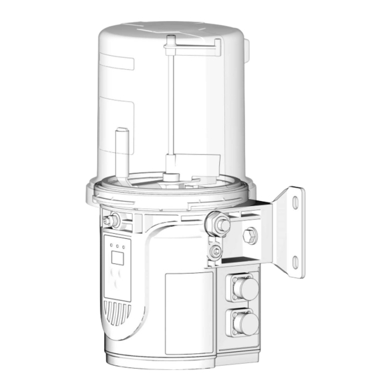
Typical Installation Typical Installation Component Identification . 1: Key: Reservoir Venting Tube (1 Liter and 0.5 Liter models only) Follower Plate (not available on all models) Pump Element Zerk Inlet Fill Fitting Cycle Indicator Connector (Controller model only) CPC Connector Controller Return to Reservoir DIN Connector (Power) -
Page 9: Divider Installation Remote
Typical Installation Divider Installation Remote . 2: CSP Direct Mount Installation . 3: Connection to fused power source (DC Models only) Proximity switch, see page 17 Pressure relief valve (required for each outlet)* Direct Mount CSP Bracket, see page 10 See Pressure Relief Valves, page 18 Direct Mount CSP Hose, see page 10 Proximity switch cable... -
Page 10: Installation
Installation Installation Choose an Installation Location AUTOMATIC SYSTEM ACTIVATION HAZARD Unexpected activation of the system could result in serious injury, including skin injection and amputa- tion. This device has an automatic timer that activates the pump lubrication system when power is connected or when exiting the programming function. -
Page 11: System Configuration And Wiring
Grounding (AC Models Only) Fuse kits are available from Graco. The following table identifies the correct fuse to use for the input voltage and the corresponding Graco Kit number. The equipment must be grounded to reduce the risk of static sparking and electric shock. -
Page 12: Recommendations For Pump Usage In Harsh Environments
25R814 Wiring and Installation Diagrams 25R816 25R818 26C916 25R822 NOTE: Wire colors provided on these pages refer only 25R823 to the Graco power cable. 25R826 25R829 NOTICE 25R730 25R832 The stirring paddle should rotate clockwise (as 25R834 viewed from the top) (F . - Page 13 Installation Power CPC DC - 5 Wire (Non-Controller) Power CPC DC - 5 Wire (Controller) Power Cable CPC DC Power Cable CPC DC Part No.: 127780 - 15 ft. (4.5 m), 127781 - 20 ft. (6.1 m), Part No.: 127780 - 15 ft. (4.5 m), 127781 - 20 ft. (6.1 m), 127782 - 30 ft.
- Page 14 Installation Power CPC DC - 3 Wire (Non-Controller) Power DIN DC - 15 ft Power Cable: Part No, 16U790 Power Cable CPC DC Part No.: 127783 - 15 ft. (4.5 m) Pin Out Pin Out -VDC Black Not Used Not Used +VDC White -VDC...
- Page 15 Installation Power DIN AC Low Level DIN DC See Technical Specifications, page 42 for ratings Pin Out Pin Out Line LL N.O. Neutral LL Com Not Used Not Used Ground Not Used . 11 . 12 3A6714H...
-
Page 16: Manual Run Button
Installation Divider Valve Indicator Cycle Inputs (M12) Part No. 124333: Cable Pin Out (M12) for 5 m Cable See Technical Specifications, page 42 for ratings. Wire Colors (F . 14) Item Color Brown White Blue Black . 14 . 13 Manual Run Button Part No. -
Page 17: Proximity Switch
Installation Manual Run Button DIN DC See Technical Specifications, page 42 for ratings Pin Out LED- LED + Button Not Used . 15 . 16 Proximity Switch NOTE: Reference ILE buyer’s guide for appropriate PNP proximity switches and cables. 3A6714H... -
Page 18: Setup
• Install a pressure relief valve before any auxiliary fitting. NOTE: A pressure relief valve may be purchased from Graco. See Pressure Relief Valves, page 18. Pressure Relief Valves Part No. Description 571028 Kit, Adj. Pressure Relief . -
Page 19: Set Pump Outlet Volume
Do not operate the pump without having a reservoir attached. NOTE: A spacer is required for operation. Only one Graco spacer can be used at a time. The pumps from NOTICE the factory have a spacer (25N814) installed on the pump element. -
Page 20: Models With A Follower Plate
Setup Models With a Follower Plate 1. Connect the fill hose to the Zerk Inlet Fill Fitting (E) . 19). . 20 4. Remove the fill hose. . 19 Models Without a Follower Plate 2. For higher viscosity fluids, start the pump, per the controller instructions, to rotate the stirring paddle 1. -
Page 21: Change Greases
Setup Prime the Pump 2. For higher viscosity fluids, start the pump, per the controller instructions, to rotate the stirring paddle during filling to prevent air pockets from forming in It is not necessary to prime the pump every time the the grease. - Page 22 Setup 3. Tighten the pump element fitting using two wrenches working in opposite directions (F . 25). . 25 3A6714H...
-
Page 23: Operation
4 and 5, see the Wiring and Installation Diagrams, twice as long as Pump ON (Run) time. If alternative page 12. ON / OFF times are required, contact Graco Cus- tomer Service for assistance. Model 2000643, 2000645, 2000648, 2000650, 2000634, 2000635, 2000638, 2000639, 25R820,... - Page 24 Operation Typical Low Level Output Response with Low Level Fluid in Oil Models . 28 3A6714H...
-
Page 25: Controller Operation
Operation Controller Operation Control Panel Overview (F . 29) . 29 3A6714H... -
Page 26: Run Mode
Operation SETUP MODE The controller operates in two modes; RUN MODE and SETUP MODE. Each mode has multiple functions. Press both the UP and DOWN arrow buttons RUN MODE together for 3 seconds to enter SETUP MODE. RUN MODE performs two functions while monitoring Alert/Alarm conditions: ON TIME and OFF TIME. -
Page 27: On Time Configuration (Cycles)
Operation After the ENTER button is 1. Press the ENTER button to pressed, the second digit advance the display. begins to blink. The ON LED and MM dot remains lighted. The first digit on the display begins to blink. This confirms This confirms that the second that the controller is ready for digit for ON TIME is being... -
Page 28: Off Time Configuration (Min./Hrs)
Operation ADVANCED PROGRAMMING OFF TIME Configuration (Min./Hrs) Notice the following on the controller: The Seven Advanced Programming Menu Descriptions are: The LED next to the • A1 - PIN Entry Enable/Setting Up the PIN Code, Clock in the OFF page 29 field is lighted. -
Page 29: Advanced Programming Menu Descriptions
Operation After all of the ADVANCED PROGRAMMING settings 4. Press the UP or Down are configured, press the ENTER button to return the arrows to select the first controller to RUN MODE. digit. Advanced Programming Menu Descriptions 5. Press the ENTER button to save the selection. - Page 30 Operation Entering a PIN Code in the Controller 8. Press the UP or Down arrows until the second After the controller is configured for PIN entry, to digit of the PIN Code dis- access SETUP MODE: plays. 1. Follow Steps 1 and 2 of ADVANCED PROGRAM- MING, (page 28).
- Page 31 Operation A2 – Prelube and Delay The Low-Level Auto Clear is an OF (OFF) or On (ON) selection. The Prelube Delay option configures the controller to set the amount of time before the Prelube cycle begins. • OF (OFF) (default) – Upon power cycle, the control- The duration of time begins after power has been ler will remain in its current Low-Level Alarm state.
-
Page 32: Alerts And Alarms
Operation Alerts and Alarms The controller monitors and displays two types of events: Alerts and Alarms. Alerts Alerts do not cause the lubrication cycle to stop. These events are automatically cleared based upon the alert received. An amber LED illuminates under ALARM on the display when an Alert occurs. -
Page 33: Alert And Alarm Scenarios
Cancel Button for 4 seconds. System An internal fault has occurred. Attempt a power cycle of the device. Fault The controller may not be recover- If the alarm does not clear, contact Graco able from this state. Customer Service. 3A6714H... -
Page 34: Maintenance
Maintenance Maintenance Frequency Component Required Maintenance Daily and at Refill Fill Fittings Keep all of the fittings clean using a clean dry cloth. Dirt and/or debris can damage the pump and/or the lubrication system. Daily Pump Unit and Reservoir Keep pump unit and reservoir clean using a clean dry cloth. -
Page 35: Recycling And Disposal
Recycling and Disposal Recycling and Disposal End of Product Life At the end of the product’s useful life, dismantle and recycle it in a responsible manner. • Perform the Pressure Relief Procedure, page 18. • Drain and dispose of fluids according to applicable regulations. -
Page 36: Troubleshooting
Reservoir is being pressurized Ensure that the vent tube is not reservoir. during filling. plugged. If the problem persists, contact Graco Customer Service or your local Graco distributor for assistance. The external controller is Motor failure. Replace the motor. functioning, but the unit is not pumping during the ON cycle. -
Page 37: Repair
Repair Repair All electrical wiring must be done by a qualified electrician and comply with all local codes and regulations. Reservoir Kits Kit No. Description 26C943 Kit Replacement, Reservoir, 1 L 26C945 Kit Replacement, Reservoir, 0.5 L Kit Replacement, Reservoir, Follower 26C944 Plate, 1 L Kit Replacement, Reservoir, Follower... -
Page 38: Parts
Parts Parts 3A6714H... - Page 39 Parts Part No./Description Ref. Part Description Qty. Ref. Part Description Qty. Baffle Reservoir, 1.0 Liter, included in kits Paddle, stirring, assembly 26C943, 26C944 (1 L Models) O-ring (2 L Models) Reservoir, 0.5 Liter, included in kits 26C945, 26C946 ( 0.5 L Models) Adapter, reservoir (2 L Models) Reservoir, 2.0 Liter, included in kits Bracket (2 L Models)
-
Page 40: Dimensions
Dimensions Dimensions Height - A Width - B Depth - C Model Inches Inches Inches 0.5 L 10.9 27.7 6.97 17.7 6.57 16.7 1 L (Grease) 12.2 31.0 6.97 17.7 6.57 16.7 2 L (Grease) 14.29 36.3 8.03 20.4 7.72 19.6 1 L (Oil) 13.89... -
Page 41: Csp Valve Bracket Mount
Dimensions 0.5L and 1L Model Pump Mount CSP Valve Bracket Mount 2L Model Pump Mount Universal Bracket Mount 3A6714H... -
Page 42: Technical Specifications
Technical Specifications Technical Specifications G-MINI Pump Metric Maximum fluid working pressure 4061 psi 28 MPa, 280 bar Power 100-240 VAC 100-240 VAC, 0.98 A, 107 VA power, 47/63 Hz, single phase, inrush/locked rotor. max 45 A (1 ms) 12 VDC 9-16 VDC;... -
Page 43: California Proposition 65
Technical Specifications California Proposition 65 CALIFORNIA RESIDENTS WARNING: Cancer and reproductive harm – www.P65warnings.ca.gov. 3A6714H... -
Page 44: Graco Standard Warranty
With the exception of any special, extended, or limited warranty published by Graco, Graco will, for a period of twelve months from the date of sale, repair or replace any part of the equipment determined by Graco to be defective.