Advertisement
Quick Links
1997/1 (T.K) 280-6832-00
clarion
APA2I50G
75W x 2 channel power amplifier
OPERATION AND INSTALLATION MANUAL
1 . INTRODUCTION
Powerful power supply circuit built in
The thorough-going circuit configuration uses low-loss power MOS FETs in the
high-efficiency PWM DC-DC converter, high-capacity low-impedance capacitors,
the large toroidal choke coil, and the copper foil dual-side printed circuit board, so
the powerful built-in power supply circuit provides stable power with margin to han¬
dle even instantaneous signal changes. The transistor is a low magnetic flux leak¬
age high-capacity El core type transistor. Furthermore, the ripple elimination pri¬
mary side choke coil directly linked to the battery and the DC-DC converter sec¬
ondary side choke coil are fastened to a pedestal with auxiliary pins to improve the
ability to withstand vibration.
Wealth of functions with superior operability
There is a gain control with a wide range of input sensitivity and a stereo/monaural
select switch. High-pass/low-pass filter circuits with continually varying cutoff fre¬
quencies are built in. Also, since all these operations are centralized on the top
surface of the heat sink, operation after installation is easy. Furthermore, since a
bass boost function to emphasize the bass region is built in, this device can also be
used as a bass amplification amplifier.
Power guard circuit
The amp has a built-in power guard function to hold down the gain during overdrive
and prevent unpleasant clipping distortion.
"
2
.
DESCRIPTION
Built-In protective circuits
These circuits prevent damage to the amp or speakers due to any abnormality such
as excess power supply voltage, speaker terminal shorts, or high temperature.
Design emphasizing sound quality
Extremely high-reliability parts have been used for even the smallest parts, includ¬
ing high through rate low noise op-amps, output-stage transistors with superior cur¬
rent linearity, and sealed relays for switching signals to bypass complex signal lines
when filters are off. This avoids all compromise and thoroughly pursues simple and
straight signal lines to make possible stable speaker driving across a broad band
with more faithful expression of the sound source. Also, each terminal group is
equipped with gold-plated input/output terminals that transmit signals reliably and
provide high reliability.
Newly designed heat sink
The main heat sink is a new design with a sleek structure. To avoid heat dispersion
fins on the surface, a tunnel-shaped heat sink is placed at the center of the printed
circuit board and powerfully cooled with an electric fan. Furthermore, the heat dis¬
persion efficiency has been greatly improved by making the air flow pathway
straight. Also, the audio section and power supply section are shielded to eliminate
interference between blocks.
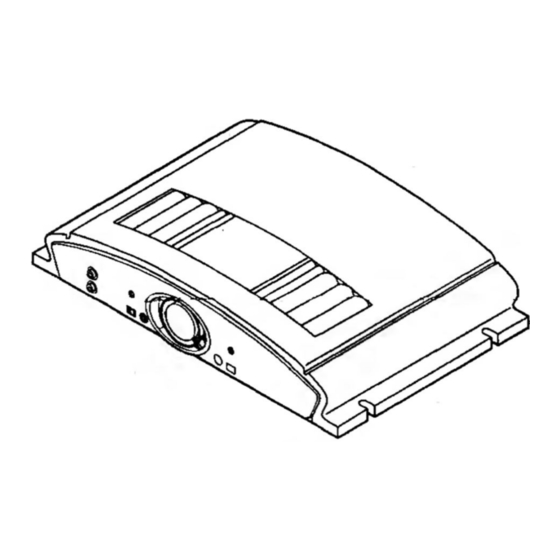
The Clarion APA2150G car audio amplifier (shown in Figure 1) is a 2-channel
amplifier that delivers 75 watt (RMS), into 2 channels or 200 watt into 1 channel.
Depending on your application, this amplifiers is an excellent choice for customizing
your own car audio system.
All connections and controls are on end panels and are straightforward and easy to
understand.
We use gold-plated RCA and barrier connectors to ensure the best electrical con¬
nection for your system. Included are external automotive-type fuses that are easy
to replace.
3
-
Amplifier Controls and Power Indicator Connections
INPUT
Turns the bass extender on and off.
The boosting volume can be adjusted between
+tdB and +12dB.
Figure 2
Front Panel Layout
Advertisement


