
Related Manuals for Baxi JSGNW 25


Summary of Contents for Baxi JSGNW 25
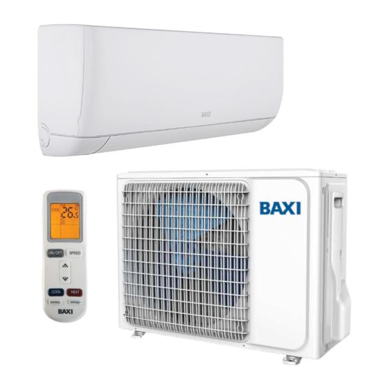
- Page 1 BAXI ASTRA: DC inverter air conditioner with heat pump mode. lnstallation and Support Manual JSGNW 25/35/50/70 LSGT 25-S/35-S/50-S/70-S...
-
Page 2: Table Of Contents
TABLE OF CONTENTS SAFETY PRECAUTIONS ................... 3 1.1. WARNINGS FOR INSTALLERS ................. 3 1.2. SPECIFIC WARNINGS FOR R32 GAS USE…………………………………………..5 1.3. WEEE WARNINGS ..................... 6 2. ACCESSORIES INCLUDED ..................7 2.1. INDOOR UNIT ..................... 7 2.2. OUTDOOR UNIT ....................7 3. -
Page 3: Safety Precautions
The appliance can be used by children aged 8 or over and by people with reduced physical, sensory or mental faculties, or who do not have the required experience or knowledge, provided they are supervised or have received instructions on using the appliance safely and understanding its intrinsic hazards. - Page 4 Do not install the indoor unit outside. Doing so may result in damage and electrical losses. During installation of the indoor unit(s), consider the distribution of air in each indoor unit in the room in order to select the most suitable position and ensure a temperature as uniform as possible within the environment.
-
Page 5: Specific Warnings For R32 Gas Use
1.2. SPECIFIC WARNINGS FOR R32 GAS USE • GENERAL R32 WARNINGS Do not mix other refrigerants or products that are not the specified refrigerant (R32) The maximum amount of R32 refrigerant allowed per room is 1.7 kg. If there is a loss of refrigerant gas, it is necessary to immediately provide complete ventilation of the environment. -
Page 6: Weee Warnings
PIPES Dimens. B Dimension Dimension Radial thickness Dimens. A Type flare nuts type (mm) (inch) (mm) flare (mm) 2 (mm) 1/4” Ø 6.35 Pipes type O 17.0 3/8” Ø 9.52 Pipes type O 13.2 22.0 1/2” Ø 12.7 Pipes type O 16.6 26.0 5/8”... -
Page 7: Accessories Included
2. ACCESSORIES INCLUDED 2.1. INDOOR UNIT NAME UNIT QUANTITY Indoor unit User manual Items Remote controller Items Batteries Items Certificates Items 2.2. OUTDOOR UNIT NAME UNIT QUANTITY Outdoor unit User manual Items Drainage connector Items Certificates Items Brass nuts Items NOTE AII the descriptions and figures shown in this manual are approximate and may differ slightly from the actual appliance purchased or its conditions of use. -
Page 8: Technical Data
TECHNICAL DATA SIZE 9000 12000 18000 24000 Type DC Inverter DC Inverter DC Inverter DC Inverter 2.55 3.60 5.30 7.03 Rated cooling power (min-max) (kW) (1.00-3.30) (1.20-3.80) (1.90-5.50) (2.90-7.30) 8.700 12.300 18.100 24.000 Rated cooling power (min-max) (kcal/h) (3.400-11.300) (4.100-13.000) (6.500-18.800) (9.900-24.900) 2.65... -
Page 9: Installation
4. INSTALLATION 4.1. CHOOSING THE INSTALLATION POSITION UNIT MODEL DIMENSIONS (mm) 792*292*201 INDOOR UNIT (WxHxD) JSGNW25 720(780)*540*260 OUTDOOR UNIT (W1(W2)xHxD) LSGT25-S 792*292*201 INDOOR UNIT (WxHxD) JSGNW35 720(780)*540*260 OUTDOOR UNIT (W1(W2)xHxD) LSGT35-S 940*316*224 INDOOR UNIT (WxHxD) JSGNW50 802(860)*535*298 OUTDOOR UNIT (W1(W2)xHxD) LSGT50-S 1132*330*232 INDOOR UNIT (WxHxD) - Page 10 • Consider the distribution of air from the indoor unit to the home and select a suitable position in order to achieve a uniform air temperature in the place of installation. • Make sure that there are no sources of heat and/or steam nearby. •...
-
Page 11: Installing The Indoor Unit
• It is possible to realize the pipe connection on Baxi Astra Indoor Unit by simply removing the below cover panel in the inferior part of the unit. Indoor... - Page 12 • Hang the indoor unit on the support using the upper tabs. Make sure that the indoor unit is in middle. Connection pipe Connection pipe Drainage pipe • Position and push the indoor unit onto the mounting plate until the hooks attach firmly into the guides and you hear them "click"...
-
Page 13: Installing The Outdoor Unit
CHECKING WATER DRAINAGE Remove the front panel from the unit according to the following instructions: Open the front fin on the indoor unit (rotate it downwards) As shown in the figures below, remove the two protections from the front panel, then remove the two fixing screws. - Page 14 Left bracket foot Right bracket foot Air inlet MODEL A (mm) B (mm) LSGT25-S LSGT35-S LSGT50-S LSGT70-S Air outlet CONNECTING THE PIPING Wrap all the pipes, the drainage pipe and the electrical cables from the top to the bottom. Wrap the pipes with tape along the route and secure them to the wall with the special clips.
-
Page 15: Refrigerant Gas Piping
5. REFRIGERANT GAS PIPING 5.1. CONNECTING THE PIPING • The method tor connecting the piping is the same tor both units, indoor and outdoor. • Connect the pipes to the unit. Tighten until the connection becomes firm and secure. Follow the directions shown in the figure. -
Page 16: Leak Test
5.2. LEAK TEST Once all the refrigerant pipes have been connected, perform a test by pressurizing the system with nitrogen to make sure there are no leaks. METHOD 1. Connect the pressure gauge unit to the service valve on the outdoor unit gas pipe. 2. -
Page 17: Refrigerant Gas Charge
5.4. REFRIGERANT GAS CHARGE lf you need to install a length of pipe longer than standard (the length tor which the unit is pre- charged), you must add the appropriate refrigerant charge. LSGT25-S LSGT35-S LSGT50-S LSGT70-S Additional charge (g/m) METHOD Calculate the refrigerant charge to be added considering the parameters specified in the "LENGTH OF REFRIGERANT CONNECTIONS"... -
Page 18: Wiring The Outdoor Unit
6.2. WIRING THE OUTDOOR UNIT Unscrew the front panel, remove the unit cover panel. • Connect the earthing wire to the corresponding screw. • Connect all the cables to the terminal block. • Reinstall the panels correctly NOTE • Connect the earthing cable correctly or it may cause the failure of any of electrical component, shocks or fire. -
Page 19: Operating Test
7. OPERATING TEST 7.1. TEST PROCEDURES • Make sure that both the liquid and gas valves are fully open. Make sure there are no refrigerant leaks. • Make sure that the electrical wiring of the indoor and outdoor units is connected as shown in "WIRING". -
Page 20: Error Codes
8. ERROR CODES The possible error codes that may appear on the display of the indoor unit are as follows: CODICE DI ERRORE PROBLEMA Fault with the room temperature sensor Fault with the refrigerant temperature sensor on the outdoor unit Fault with the refrigerant temperature sensor on the indoor unit Fault with the fan motor on the indoor unit (PG motor) E5 (5E) - Page 21 2017/1369 – Energy Labelling Regulation 2012/206 – Ecodesign Regulation 2011/626 – Energy Labelling Regulation 2011/65/UE – RoHS2 Hazardous Substances Directive 36061 Bassano del Grappa (VI) - ITALY Via Trozzetti, 20 Servizio Clienti: Tel. +39 0424-517800 – Fax +39 0424-38089 www.baxi.it...