Table of Contents
Advertisement
2022
WARNING
To prevent serious injury or death:
1-
Lock-out/tag-out before performing maintenance.
2-
If system power is required (e.g., smoke detector mainte
nance), disable power to blower, remove fan belt where
applicable, and ensure all controllers and thermostats are
set to the "OFF" position before
performing maintenance.
3-
Always keep hands, hair, clothing, jewelry, tools, etc.,
away from moving part
Table Of Contents
. . . . . . . . . . . . . . . . . . . . . . . . . . . . . . . . .
. . . . . . . . . . . . . . . . . . . . . . . . .
. . . . . . . . . . . . . . . . . . . .
. . . . . . . . . . . . . . . . . . . . . . . . . . . . . . . . . . . .
. . . . . . . . . . . . . . . . . . . . . . . . . . . . . . . . . . . . .
. . . . . . . . . . . . . . . . . . . . . . . . . . . . . . . .
. . . . . . . . . . . . . . . . . . . . . . . . . . . .
. . . . . . . . . . . . . . . . . . . . . . .
. . . . . . . . . . . . . . . . . . . . . . . . . .
. . . . . . . . . . . . . . . . . . . . . . . . . . . . . . . . .
. . . . . . . . . . . . . . . . . . . . .
. . . . . . . . . . . . . . . . . . . . . . . . .
. . . . . . . . . . . . . . . . . . . . . . . . .
. . . . . . . . . . . . . . . . . . . . . . . . . . . .
Use this QR code to download the mobile service app. Follow the prompts
to pair the app with the unit control system and configure the unit. Refer to the
"Download Mobile App" section in this manual and the Setup Guide provided
with this unit. The QR code is also available in the unit control area.
The app can be downloaded from the appropriate iOS or Android store.
s.
Page 2
Page 3
Page 4
Page 4
Page 4
Page 5
Page 6
Page 6
Page 6
Page 8
Page 9
Page 10
. . . . . . . . . . . . . . . . .
Page 10
. . . . . . . . .
Page 10
. . . . . . . . .
Page 11
. . . . . . . . . . . .
Page 13
Page 15
Page 18
Attention!
Look for the following icon.
INSTALLATION
INSTRUCTIONS
PACKAGED UNITS
508287-01
10/2022
Improper installation, adjustment, alteration, ser
vice or maintenance can cause property damage,
personal injury or loss of life. Installation and ser
vice must be performed by a licensed professional
HVAC installer or equivalent, service agency, or the
gas supplier.
. . . . . . . . . . . . . . . . . . . . . . . . . . .
. . . . . . . . . . . . . . . . . . . . . . . .
. . . . . . . . . . . . . . . . . . . . . . . . . . .
. . . . . . . . . . . . . . . . . . . . . . . . . . . . . . . . . . . .
(7.5 Ton)
(8.5 Ton)
(10 Ton)
(12.5 Ton)
. . . . . . . . . . . . . .
Page 24
Page 26
. . . . . . . . . . . .
Page 27
Page 27
Page 28
. . . . . . . . . . . . . . . . . . .
Page 29
Page 31
. . . . . . . . . . . . . . . . . . .
Page 37
. . . . . . . . . . . . .
Page 37
Advertisement
Table of Contents

Related Manuals for Lennox LGT092H


Summary of Contents for Lennox LGT092H
-
Page 1: Table Of Contents
2022 INSTALLATION INSTRUCTIONS WARNING To prevent serious injury or death: LGT/LCT092H Lock-out/tag-out before performing maintenance. (7.5 Ton) If system power is required (e.g., smoke detector mainte LGT/LCT102H nance), disable power to blower, remove fan belt where (8.5 Ton) applicable, and ensure all controllers and thermostats are LGT/LCT120H set to the “OFF”... -
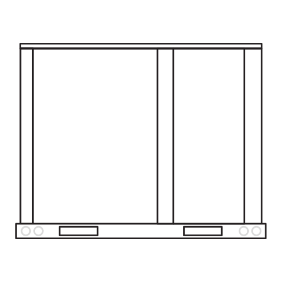
Page 2: Dimensions
CAUTION As with any mechanical equipment, contact with sharp sheet metal edges can result in personal in jury. Take care while handling this equipment and wear gloves and protective clothing. LGT/LCT092, 102, 120, & 150 DIMENSIONS - GAS HEAT SECTION SHOWN 6-1/8 5-5/8 BOTTOM SUPPLY... -
Page 3: Parts Arrangements
LGT092, 102, 120, 150 PARTS ARRANGEMENT BLOWER CONDENSER REHEAT COIL EVAPORATOR (DIRECT DRIVE) (OPTIONAL) FANS COIL FILTERS (FOUR - 20 X 25 X 2”) CONDENSER COIL ECONOMIZER (OPTIONAL) WIFI ANTENNA UNIT IGNITION CONTROLLER CONTROL COMBUSTION WIRELESS AIR INDUCER BOARD GAS VALVE COMPRESSORS BURNERS CONDENSATE... -
Page 4: Shipping And Packing List
Authorities having jurisdiction should be consulted before installation. The LGT092H / 150H gas/electric packaged rooftop unit is available in 130,000, 180,000, or 240,000 Btuh heating inputs. The LCT092H / 150H cooling packaged rooftop unit is the same basic design as the LGT unit except for the heating section. -
Page 5: Unit Support
Use of this unit as a construction heater or air conditioner Roof Mounting with C1CURB7*B is not recommended during any phase of construction. 1- The C1CURB7*B roof mounting frame must be Very low return air temperatures, harmful vapors and installed, flashed and sealed in accordance with the operation of the unit with clogged or misplaced filters will instructions provided with the frame. -
Page 6: Duct Connection
B-Horizontal Discharge Applications A trap must be installed between drain connection and an open vent for proper condensate removal. See figure 3 or 1- Units installed in horizontal airflow applications must 4. It is sometimes acceptable to drain condensate onto use a horizontal conversion kit K1HECK00. - Page 7 2- Remove six screws from filter access door. Refer to CONDENSATE BOTTOM DRAIN CONNECTION figure 6. UNITS WITH HINGED PANELS UNIT FILTER DOOR CONDENSATE DRAIN PAN DRAIN MULLION CAULK AROUND CONDENSATE COUPLING REMOVE OPEN VENT THREE SCREWS (PER HINGE) MOUNTING FIGURE 6 FRAME 3- Open filter access door hinges and carefully remove...
-
Page 8: Gas Piping
Bottom Drain Connection Connect Gas Piping (Gas Units) 1- Open blower and heat access doors. See figure 5. 2- Remove six screws from filter access door. Refer to Before connecting piping, check with gas company or figure 6. authorities having jurisdiction local code... -
Page 9: Pressure Test Gas Piping
Pressure Test Gas Piping (Gas Units) BOTTOM ENTRY GAS PIPING THROUGH THE CURB When pressure testing gas lines, the gas valve must MULLION BETWEEN be disconnected and isolated. Gas valves can be HEAT AND COMPRES damaged if subjected to more than 0.5 psig (3.48kPa). SOR SECTIONS See figure 12. -
Page 10: High Altitude Derate
3- Connect separate 120v wiring optional High Altitude Derate field-powered GFCI outlet. Route field wiring in Locate the high altitude conversion sticker in the unit conduit between bottom power entry and GFCI. See literature bag. Fill out the conversion sticker and affix next figure 14. -
Page 11: Electrical Connections - Control Wiring
3- Connect thermostat wiring to Unit Controller on the Electrical Connections - Control Wiring lower side of the controls hat section. NOTE ‐ Optional wireless sensors are available for use 4- Wire as shown in figure 15 for electro-mechanical with this unit. Refer to the instructions provided with electronic thermostats. - Page 12 Wire runs over 150 feet (mm): FIELD WIRING IN ZONE SENSOR MODE Use a local, isolated 24VAC transformer such as Lennox (Zone Sensor Mode) cat #18M13 (20VA minimum) to supply power to RH sensor as shown in figure 19. Use two shielded cables...
-
Page 13: Blower Operation And Adjustments
Initiate blower only (G) demand at thermostat according Blower Operation to instructions provided with thermostat. Unit will cycle on Units are equipped with variable speed, direct drive thermostat demand. The following steps apply to blowers. The supply CFM can be adjusted by changing applications using typical... - Page 14 LOCATION OF STATIC PRESSURE READINGS INSTALLATIONS WITH DUCTWORK INSTALLATIONS WITH CEILING DIFFUSERS ROOFTOP UNIT ROOFTOP UNIT RETURN AIR READING LOCATION RETURN AIR READING RE RE SUPPLY SUPPLY LOCATION TURN TURN FIRST BRANCH OFF OF MAIN RUN MAIN DUCT RUN SUPPLY AIR SUPPLY AIR READING READING...
-
Page 15: Direct Drive Start-Up
Blower calibration is required only on units that are newly Direct Drive Blower Start-Up installed or if there is a change in the duct work or air filters after installation. Use the mobile service app to navigate The supply CFM can be adjusted by changing the to the SETUP>TEST &... - Page 16 BLOWER DATA BLOWER TABLE INCLUDES RESISTANCE FOR BASE UNIT ONLY (NO HEAT SECTION) WITH DRY INDOOR COIL AND AIR FILTERS IN PLACE. FOR ALL UNITS ADD: 1 − Wet indoor coil air resistance of selected unit. 2 − Any factory installed options air resistance (heat section, Economizer, etc.) 3 −...
- Page 17 BLOWER DATA FACTORY INSTALLED OPTIONS/FIELD INSTALLED ACCESSORY AIR RESISTANCE - in. w.g. Gas Heat Exchanger Filters Return Wet Indoor Coil Electric Econo Reheat Volume Standard Medium High Heat mizer Coil Adaptor MERV 8 MERV 13 MERV 16 Heat Heat Heat Plate 092, 102 120, 150 1750...
-
Page 18: Cooling Start-Up
B-R410A Refrigerant Cooling Start-Up Units charged with R410A refrigerant operate at much IMPORTANT-The crankcase heater must be energized higher pressures than R22. The expansion valve and for 24 hours before attempting to start compressor. Set liquid line drier provided with the unit are approved for use thermostat so there is no demand to prevent with R410A. - Page 19 D-Refrigerant Charge and Check NOTE - Pressures are listed for sea level applications. WARNING-Do not exceed nameplate charge under 4- Use the same thermometer to accurately measure any condition. the liquid temperature (in the outdoor section). This unit is factory charged and should require no further adjustment.
-
Page 20: Lgt/Lct092H
TABLE 4 581114-01 LGT/LCT092 Normal Operating Pressures Outdoor Coil Entering Air Temperature 65 F 75 F 85 F 95 F 105 F 115 F Suct Disc Suct Disc Suct Disc Suct Disc Suct Disc Suct Disc (psig) (psig) (psig) (psig) (psig) (psig) (psig) -
Page 21: Lgt/Lct102H
TABLE 5 581115-01 LGT/LCT102 Normal Operating Pressures Outdoor Coil Entering Air Temperature 65 F 75 F 85 F 95 F 105 F 115 F Suct Disc Suct Disc Suct Disc Suct Disc Suct Disc Suct Disc (psig) (psig) (psig) (psig) (psig) (psig) (psig) -
Page 22: Lgt/Lct120H
TABLE 6 581116-01 LGT/LCT120 Normal Operating Pressures Outdoor Coil Entering Air Temperature 65 F 75 F 85 F 95 F 105 F 115 F Suct Disc Suct Disc Suct Disc Suct Disc Suct Disc Suct Disc (psig) (psig) (psig) (psig) (psig) (psig) (psig) -
Page 23: Lgt/Lct150H
TABLE 7 581117-01 LGT/LCT150 Normal Operating Pressures Outdoor Coil Entering Air Temperature 65 F 75 F 85 F 95 F 105 F 115 F Suct Disc Suct Disc Suct Disc Suct Disc Suct Disc Suct Disc (psig) (psig) (psig) (psig) (psig) (psig) (psig) -
Page 24: Prognostic & Diagnostic Sensors
refrigeration circuit. These temperatures are used as Diagnostic Sensors feedback in certain modes of unit operation. In addition, the Unit Controller uses these temperatures to initiate Units are equipped with four factory-installed thermistors alarms such as loss of condenser or evaporator airflow (RT46 - RT49) located on different points on the and loss of charge. - Page 25 THERMISTOR LOCATION - CONDENSER COIL RT48, RT49 23V50 YELLOW RT48 23V50 BLUE RT49 DETAILS NOT TO SCALE FIGURE 24 Page 25...
-
Page 26: Warning
This unit is equipped with an automatic spark ignition Gas Heat Start-Up (Gas Units) system. There is no pilot. In case of a safety shutdown, move thermostat switch to OFF and return the thermostat FOR YOUR SAFETY READ BEFORE LIGHTING switch to HEAT to reset ignition control. -
Page 27: Heating Operation And Adjustments
5- Turn gas valve switch to OFF. See figure 25. On 3- Spark ignitor energizes and gas valve solenoid Honeywell VR8305Q gas valves, turn the knob on the opens. gas valve clockwise to “OFF”. Do not force. See 4- Spark ignites gas, ignition sensor proves the flame figure 26. -
Page 28: Cooling Operation
C-Three-Stage Thermostat Cooling Operation This is a summary of cooling operation. Refer to the 1-Economizer With Outdoor Air Suitable sequence of operation provided in the Engineering Y1 Demand - Handbook or Service Manual for more detail. Compressors Off Note - Free cooling is locked-out during reheat operation. Blower Cooling Low* Refer to hot gas reheat start-up and operation section for Dampers Modulate... -
Page 29: Modulating Hot Gas Reheat
The reheat setpoint can be adjusted by changing mobile Modulating Hot Gas Reheat Start-Up And service app Settings - Control menu. A setting of 100% Operation will operate reheat from an energy management system General digital output. Hot gas reheat units provide a dehumidifying mode of The reheat setpoint can also be adjusted using an operation. - Page 30 COOLING MODE REFRIGERANT ROUTING FIGURE 28 Default Reheat Operation TABLE 9 Reheat Operation - Three Cooling Stages - Default TABLE 8 T'stat & Humidity De Reheat Operation - Two Cooling Stages - Default Operation mands T'stat & Humidity Compressor 1 Full Load, Operation Demands Reheat Only...
-
Page 31: Service
Service REMOVE FILTERS The unit should be inspected once a year by a qualified service technician. CAUTION Label all wires prior to disconnection when servic ing controls. Wiring errors can cause improper and dangerous operation. Verify proper operation after servicing. PULL TO REMOVE A-Filters... - Page 32 6- Replace burners and screws securing burner. Under normal operating conditions, the combustion air inducer wheel should be checked and cleaned prior to the 7- Replace access panel. heating season. However, it should be examined periodically during the heating season to establish an 8- Restore electrical power and gas supply.
- Page 33 G-Evaporator Coil HEAT EXCHANGER ASSEMBLY Inspect and clean coil at beginning of each cooling season. HEAT Clean using mild detergent or commercial coil cleaner. EXCHANGER TUBE Flush coil and condensate drain with water taking care not to get insulation, filters and return air ducts wet. COMBUSTION AIR INDUCER H-Supply Air Blower Wheel...
- Page 34 UVC ASSEMBLY UVC LAMP UVC ASSEMBLY ASSEMBLY SECURED DOOR WITH 3 SCREWS SWITCH FIGURE 36 K-UVC Light Annual Lamp Replacement WARNING When field-installed, use only UVC Light Kit assembly 106882-01 (21A93) with this appliance. Personal Burn Hazard. Personal injury may result from hot lamps. During replacement, allow lamp to cool for 10 minutes be...
- Page 35 3- Open the blower access door. If UVC lamp does not come on: 4- Remove the screw in wire tie from the UVC assembly 1- Check Power Wiring: Disconnect 1/4” QC (quick and disconnect the 4-pin connector from the lamp end. connects) of the UVC cable near the UVC assembly.
- Page 36 TURN POWER ON; LAMP LEDS NOT LIT CONNECTORS FOR ALL THE CHECK LAMP LEDS LAMPS ARE PROPERLY ENGAGED LAMP LEDS LIT? CALL LENNOX TWO PAIR, PIN TO PIN TECH SUPPORT ON EACH PAIR 1-800-453-6669 (SEE DETAIL A) LAMPS BANDS CONTINUITY...
-
Page 37: Field-Installed Accessories
TABLE 12 Field-Installed Accessories 581024-01 When field-installing the following accessories, refer to Units With Hot Gas Reheat the latest online installation instruction. RTU Menu > Settings “RTU Options” > Dehumidifier TABLE 11 Para Factory Field Accessory Instruction # meter Setting Setting Description Economizer... - Page 38 Dual-Stage = D U = Unconfigured Unconfigured = U Power Exhaust Control 4] [5] Network Module Not Installed = N N = Not Installed Damper Position = A L = LonTalk (Lennox) A34 Pressure Sensor = C FIGURE 40 Page 38...
- Page 39 Phase / Voltage Detection * [5] [6] IAQ Options N = Not Installed N = Not Installed 1 = Enabled Internal (Lennox) 1 = UV Lamp Installed 2 = External (A42) Phase Detection 2 = Bipolar Ionizer Installed on DI-2...
- Page 40 START-UP REPORT Job Name:___________________________________ Inspections and Checks Store No.___________Start-Up Date:______________ R22 j R410A j Damage? If yes, reported to:____________________________ Address:_____________________________________ City:______________________________State:______ Verify factory and field-installed accessories. Start-Up Contractor:____________________________ Check electrical connections. Tighten if necessary. Technician:___________________________________ Supply voltage: L1-L2______L1-L3_____L2-L3_____ Model No.:___________________________________ If unit contains a 208-230/240 volt transformer: Serial No.:____________________________________ Check primary transformer tap j...