
Related Manuals for Fujitsu UTY-RVRU


Summary of Contents for Fujitsu UTY-RVRU
- Page 1 REMOTE CONTROLLER (WIRED TYPE) OPERATION MANUAL (full) WIRED REMOTE CONTROLLER Keep this manual for future reference. UTY-RVRU PART No. 9373329961-03...
-
Page 2: Table Of Contents
OPERATION MANUAL (full) Away ................17 4-5-1 Eco Away (setting) ..........17 PART No. 9373329961-03 WIRED REMOTE CONTROLLER 4-5-2 Away ..............18 4-5-3 Vacation ..............18 Cleaning..............18 Contents 4-6-1 Panel Cleaning ............18 1 INTRODUCTION 4-6-2 Filter Sign Reset ............ 18 Safety precautions .......... - Page 3 Screen structure 5-1-1 5-1-2 ♦ 5-4-1 5-4-1-1 ♦ 4-1-1 5-4-1-2 ♦ ♦ ♦ 4-2-1 ♦ ♦ 4-2-2 ♦ 4-2-3 5-2-1 ♦ ♦ 4-3-1 5-4-2 5-2-2 4-3-2 5-4-2-1 ♦ 4-3-3 5-4-2-2 5-2-3 5-4-2-3 4-3-4 ♦ ♦ 5-2-4 5-2-5 4-4-1 5-2-6 4-4-2 4-5-1 4-5-2 5-3-1...
-
Page 4: Introduction
1 INTRODUCTION 1-2 System outline 1-2-1 Terminology 1-1 Safety precautions System related terms (♦ is for VRF system) • The “SAFETY PRECAUTIONS” indicated in the manual (a) VRF system ♦: contain important information pertaining to your safety. Be VRF (Variable Refrigerant Flow) is a large multi-split sure to observe them. system that effectively air conditions a wide variety of spaces from large buildings to personal residences. -
Page 5: Password Configuration
1-2-2 Password configuration 1-4 Before operation or setting This unit can set the following 2 kinds of passwords: 1-4-1 Wake the controller (a) Admin password If the standby screen is displayed, tap the screen to display This is a password for administrator. Password is re- the temperature setting screen (home screen). quested by the setting which requires management. -
Page 6: Password
1-4-4 Password 2 BASIC OPERATION ■ Password screen 2-1 Main screen configuration A password has been set for the items on which this The main screen has 3 basic operation screens and 1 other screen is displayed. Check setting screen. the password or operation permissions with the admin- istrator. -
Page 7: Operation On/Off
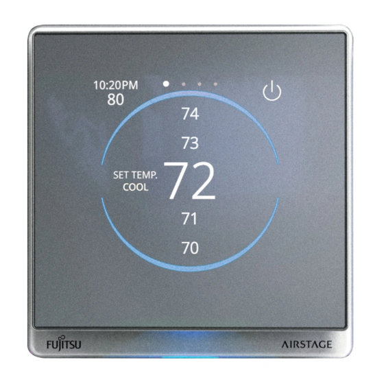
(e) Information area 2-3 Temperature setting The displayed contents differ depending on the screen and settings. 2-3-1 Temperature screen Tap here to move to the status screen. For details, refer This is the home screen of this product. to “5-4-1-1 Status” ■ Example of cooling mode When an error occurs, an error icon is displayed. ■... -
Page 8: Operation Mode Setting
3 Other settings 2-4 Operation mode setting ■ Other settings screen NOTE The operation modes that can be set differ depending on the indoor unit model, air conditioner system, and control- ler settings. 3-1 Eco Away When temporarily unattended, enable this function to oper- ate at a preset temperature. -
Page 9: Day Selection Screen
(a) back button Tap to return to the previous screen. (b) home button Tap to move to the temperature setting screen (home screen). (c) Weekly timer 1, 2 Weekly operation schedule can be set. Two schedule patterns can be created. Up to 8 times setting for each day can be set. -
Page 10: Operation Mode Screen
3-2-4 Operation mode screen (b) Cancel button Tap to display a confirmation screen. Tap [OK] on the confirmation screen to return to the previous screen. (c) OK button Tap to confirm the setting and return to the previous screen. When the settings are changed, a confirmation screen will be displayed. Tap [OK] on the confirmation screen to return to the previous screen. 3-2-6 Time screen (a) Operation mode menu Select and tap a operation mode. Swipe up or down on any hidden items. NOTE If set “3-2-7 Operation Setting screen”... -
Page 11: Operation Setting Screen
3-2-7 Operation Setting screen (c) Toggle button Enable the days of the week when timer operation is not performed. Enable Disable NOTE This item is reset after the day of the week. 3-2-9 Create the schedule ■Select timer Tap the timer (1 or 2) to create the schedule. - Page 12 ■Operation mode ■Copy day * This item does not need to be set when operation Off. (1) Tap [Copy Day]. (1) Swipe up or down to (2) Select the day of the select an operation week to copy. mode, then tap. (3) Select the day of the (2) Tap [OK]. week to paste. (4) Tap [OK].
-
Page 13: Detail
4 Detail (a) Backward button Tap to return to the previous screen. (b) Home button NOTE Tap to move to the temperature setting screen (home Some items may not be displayed depending on the screen). model of the indoor unit or the settings of the controller. (c) Back to top button Tap to display the top of the scroll screen. -
Page 14: Individual Hold
4-1-1 Individual hold ■ Unit screen (air outlet selection) Cassette type Individually set the airflow direction or swing for indoor units with multiple air outlets. (a) Individual Hold menu Tap to move to the “Individual hold” screen. NOTE This function can only be used with compatible indoor units. Step 1. Selecting the indoor unit to set Tap the indoor unit to be set to move to the air outlet selec- tion screen. -
Page 15: Comfort Function
4-2 Comfort Function 4-3 Energy-saving 4-2-1 Powerful 4-3-1 Economy In the Powerful operation, the air conditioner will operate at Reduces power consumption by operating with reduced maximum power and strong airflow to cool down or warm up capacity. the room quickly. (a) Toggle button (a) Toggle button Tap to toggle enable/disable. Tap to toggle enable/disable. - Page 16 4-3-2-1 Auto Saving (b) Set time menu Tap the “Absence Detection Time” and set the time. When the absence continues for the set time, the operation switches to energy saving operation. (1) Swipe up or down to If no one enters the room during the set time (15, 30, 60, 90, select the detection 120, 180 minutes), the set temperature will be automatically time and tap it.
-
Page 17: Energy Saving Fan
4-3-3 Energy saving fan 4-3-4-2 Cool/Dry or Heat (setting) When the set temperature is reached during cooling opera- NOTE tion, the fan operates intermittently and power is saved. The setting method for Cool/Dry and Heat is the same. ■ Example of the Cool/Dry screen (a) Toggle button Tap to toggle enable/disable. -
Page 18: Safety Shield
4-5-1-1 Eco Away (temperature setting) 4-4 Safety shield Set the operating temperature when unattended. 4-4-1 Anti-Freeze Anti-Freeze is a function that performs low temperature heat- ing operation to prevent freezing of water lines and equip- ment, when air conditioning operation is off, in regions where outside temperature may drop below freezing. NOTE If water lines are far from the unit or within exterior walls, this function may not provide enough anti-freeze protec-... -
Page 19: Away
4-5-2 Away 4-5-3 Vacation When operation stopped, it switches to indoor protection This function disables the weekly timer when the machine is operation. left unattended for a long period of time, such as on vaca- tion. NOTE NOTE This function requires RC sensor to be enabled. Refer to “5-2-6 RC (Remote Controller) Sensor”. -
Page 20: Setting
5 Setting 5-1-1 Auto Off Timer When indoor unit operation is started by the Operation button of this unit, operation stops after the set time. 5-1-1-1 5-1-1-2 5-1-1-3 (a) Backward button Tap to return to the previous screen. (a) Backward button (b) Home button Tap to return to the previous screen. -
Page 21: Outdoor Unit Low Noise
5-1-1-3 Start/Stop Time 5-1-2-2 Time Range (1) When specifying a If [Range Spec.] is selected in “5-1-1-2 Time Range”, specify time range for the the range here. “Outdoor unit low NOTE noise”, tap [Range Spec.] and when The display format of the time varies depending on the enabling the setting settings. -
Page 22: Initial Setting
5-2-1 RC (Remote Controller) Group Name 5-2 Initial setting The remote controller group name can be set or changed. NOTE Some items may not be displayed depending on the model of the indoor unit or the settings of the controller. For each description, refer to the appropriate heading num- ber. -
Page 23: Admin Password
5-2-2 Admin password 5-2-2-2 Change Setting NOTE Some items may not be displayed depending on the model of the indoor unit or the settings of the controller. 5-2-2-1 5-2-2-2 5-2-2-1 Change Password The admin password setting and changes can be performed. Tap [ ] to display the entered number. -
Page 24: Display Item
5-2-3 Display Item (a) Backward button Tap to return to the previous screen. NOTE (b) Home button Some items may not be displayed depending on the Tap to move to the temperature setting screen (home model of the indoor unit or the settings of the controller. screen). -
Page 25: Rc (Remote Controller) Sensor
5-2-6 RC (Remote Controller) Sensor (a) Backward button Tap to return to the previous screen. This setting uses the sensor of this unit to sense the room (b) Home button temperature. The room temperature can be sensed at a posi- Tap to move to the temperature setting screen (home tion, closer to the person than the indoor unit sensor. -
Page 26: Temperature Unit
5-3-2-2 Time 5-3-3 Temperature unit Set the current time. (1) Tap the temperature unit to use. NOTE (2) Tap [ ] to return The display format depends on the setting. to the previous screen. (1) Tap the item to set. 5-3-4 Language (1) Tap the language to... -
Page 27: Backlight
5-3-7 Backlight 5-3-7-3 Time after lighting Select whether to off or dim the backlight after operating this remote controller. Off: After the time set in “Automatic Off Time” (refer to 5-3-7-4) has passed, the backlight will turn off. 5-3-7-1 Dimming: After the time set in “Automatic Off Time” (refer to 5-3-7-4) has passed, the brightness of the 5-3-7-2 backlight will be reduced and one of the follow- ing will be displayed: 5-3-7-3 •... -
Page 28: Service
5-4-1 Maintenance NOTE This function can be used with software version “E134V- 5-4-1-1 Status 02P00L03” or later. (1) Swipe up and down to move the screen. To check the error 5-4 Service that has occurred, tap [Error Informa- These function is for administrator and service personnel. tion]. -
Page 29: Operation Tips
5-4-2-3 Version 6-1-4 Heat pump system The software version of this controller is displayed on the (a) Refer to the following table: right. Status Selectable Not selectable Other indoor unit is in cool- Cool, Dry Custom Auto, ing operation. Heat, Fan Other indoor unit is in dehu- Cool, Dry Custom Auto, midifying operation. -
Page 30: Others
United States customary units are provided for refer- ence only. In cases where exact dimensions and tolerances are required, always refer to metric units. 7-2 Specifications Model Name UTY-RVRU Input voltage DC 12 V Power consumption Max. 1.0 W 4 inch TFT LCD Display (480 ×...